Kontaktaufnahme
Live-Chat mit Tektronix-Vertretern. Verfügbar von 9 bis 17 Uhr CET Geschäftstage.
Kontaktieren Sie uns telefonisch unter
Verfügbar von 9 bis 17 Uhr CET Geschäftstage.
Download
Laden Sie Handbücher, Datenblätter, Software und vieles mehr herunter:
Feedback
C-PHY Transmitter Solution
TekExpress MIPI C-PHY Transmitter Test Application CPHY20 / 6-CMCPHY20 Datasheet
Weitere Informationen
- ATI-Hochleistungsoszilloskop DPO70000SX
- MSO der Serie 6 B
- Weitere Software Modelle entdecken
Online lesen:
The Tektronix TekExpress® C-PHY20 application offers a complete physical layer test solution for transmitter conformance and characterization as defined in the MIPI C-PHY v2.0, v1.1 and v1.0 specification. TekExpress C-PHY solution provides easy way to measure and characterize C-PHY data links. TekExpress C-PHY v2.0 automated test solution along with 70K DX/SX or a MSO6/6B oscilloscopes provides an easy way to test, debug and characterize the electrical and timing measurements of C-PHY.
Key features
Transmitter testing:
- Dynamic Symbol Rate: Supports Dynamic Symbol Rate updating for the waveform captured.
- Measures the rise time and fall time of the DUT C-PHY signals.
- Verifies that the static point common mode voltage VCPTX of the trio signal is within the transmitter limit.
- C-PHY Tx 2.0 delivers 100% Automated TekExpress based C-PHY solution for all the Tx measurement.
- Supports CPHY specification version for MIPI CPHY 1.0, 1.1, and 2.0
- Live and pre-acquired waveform Analysis
- Easily select and configure the desired tests
- Modify limits of test parameters for debug, margin, and characterization testing
- Supports LP-TX and HS-TX signaling tests at highest symbol rate – 8GS/s
- Options to select LVLP and LVHS and ALP mode functionality for LP and HS tests.
- Supports Eye Diagram Test with CTLE for symbol rates above 3.5 GS/s and without CTLE at symbol rates below 3.5 GS/s
- Supports Hexagonal shaped eye diagram for devices with maximum operating symbol rates <1 GS/s and for devices with maximum operating symbol rates ≥1 GS/s, a diamond shaped eye diagram is displayed.
- Supports horizontal mask movement to a position where there are zero mask hits.
- User defined options to select three reference templates (Short, Standard, and Long) for differential insertion loss that are applicable for all symbol rates.
- Provision to test LP-TX timing and behavioral tests such as initialization (INIT), Ultra-Low Power State (ULPS), and Bus Turnaround (BTA)
- Supports HS burst signaling tests in the HS Unterminated Mode
- Support HS-TX Calibration Preamble measurements
- Provision to run in user defined mode with user defined parameters for triggering the LP-HS signals
- Manual Cursor Mode support to enable the user to capture and measure the desired LP-HS regions.
- Debug Mode support to load waveforms on Ref and Math channels for Analysis
- Reporting measurement test run details and repeatability with option to save the waveforms only for fail test run
- Verifies that the common-mode voltage mismatch (ΔVCMTPX) of the DUT Data Lane HS transmitter is less than the maximum conformance limit.
- Verifies that the common-mode level variation is between 50 MHz to 450 MHz.
- Verifies that the common-mode level variation is above 450 MHz.
- Modifies limits in TekExpress for debug and characterization.
Applications
- Automotive camera and display
- Mobile camera and display
- Camera CMOS Image sensors
- Display Driver ICs
- Application processor for mobile devices
- Wearable technologies
- Internet of Things(IoT)
- Drones
- Personal Computers
MIPI C-PHY transmitter test
MIPI® C-PHY v2.0 provides throughput high performance over bandwidth limited channels for connecting to peripherals, including displays and cameras. This interface allows the system designers to easily scale the existing MIPI® Alliance Camera Serial Interface (CSI-2) ecosystem to support higher resolution image sensors with less power consumption.
MIPI® C-PHY and MIPI® D-PHY are pin compatible, allowing connections to the companion device with either technology. C-PHY was designed to coexist on the same IC pin as D-PHY so that dual-mode devices can be developed.
MIPI C-PHY introduces 3-phase symbol encoding offering 2.28 bits per symbol to transmit data symbols on 3-wire lanes or trios, where each trio includes an embedded clock.
C-PHY signals have three levels and they are single-ended. They are represented as LineA, LineB, and LineC. At any given point in time, no signals are at the same voltage levels. The receiver side is differential and displays four different voltage levels; Strong 1, Weak 1, Strong 0, and Weak 0. The receiver however views either logic 1 or logic 0.
C-PHY clock recovery
C-PHY uses a unique mechanism for clock recovery. C-PHY 2.0 implements a custom clock recovery algorithm referred to as Triggered Eye. In this model, the first zero crossing of the three differential signals is used as a trigger point for clock recovery and to render the eye diagram.
The mask is aligned to right most passing position for triggered eye.
C-PHY transmitter test measurements
For meeting the conformance requirements of C-PHY v2.0 CTS v1.0, following tests/measurements are executed.
- LP tests
- HS Timing tests
- HS Electrical tests
- LP Timing Tests manual
- BIDIR Timing Tests
- DC Level Test
- CAL PRE Timing Tests
Custom-triggered eye diagram
The following figure displays the TekExpress C-PHY TX Test software being configured for a custom-triggered eye diagram, with auto mask position for optimal mask placement.
Eye diagram analysis
The Jitter and Eye diagram rendering performed over the entire record length helps designers to characterize the devices better by displaying anomalies of the device over an extended period. The software allows you to run the eye diagram analysis for 3M UI (1M on each differential pair) and overnight run for a detailed characterization.
Insertion loss
As part of characterizing the device, designers need to embed or de-embed insertion loss. This is supported using the filter files as shown in the following figure.
Signaling and termination
C-PHY signaling is similar to D-PHY. For instance, it dynamically switches from LP mode to HS Mode in the timing measurements defined for C-PHY.
The following figure is from the MIPI Alliance C-PHY specification v2.0. It shows the structure of a C-PHY signal (HS data transmission in Burst).
To take measurements during this switchable termination mode, load boards or termination boards are needed. The physical setup for taking these measurements require an oscilloscope, probes, and a termination board.
The following figure shows the physical set up for HS measurements. Termination board and probes are not required for HS measurements, you can connect SMA cables directly.
Dynamic Symbol Rate
Quite often the end user is not aware of the exact symbol rate in the system/device under test. Dynamic Symbol Rate feature addresses this by enabling user to measure/calculate and validate signal’s symbol rate before running measurement, if he/she is not aware of the symbol rate. This helps in enabling user to save time by avoiding unnecessary iterations because of invalid symbol rate.
Multi-Run
Multi-Run is an option to the user to perform the measurements for a user defined number of iterations. The report would list the results for all the iterations, and the statistics table would additionally compute and report the statistics across the measured values.
TekExpress Automated Solution
The Tektronix TekExpress C-PHY application runs on DPO/MSO 70000 DX/SX with Option-DJA , Series 6 Series B MSO with Options, 6-DJA and Option 6-WIN installed (Windows 10 operating system). The close integration of the oscilloscope and test software provides an automated, simple, and efficient way to test C-PHY transmitter interfaces and devices consistent to the requirements of the C-PHY v2.0, Conformance Test Specification revision 1.0.
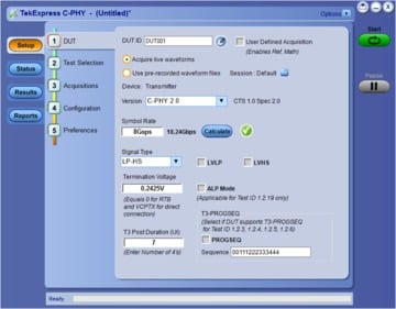
Measurement setup and test execution is simple with the C-PHY Transmitter software. The intuitive Graphical User Interface (GUI) is laid out to represent the workflow from setup through testing, letting you focus on design and debug instead of setting up the measurements.
Simply select tests from the menu for HS, LP, and HS-LP groups as per specifications.
You can view the schematic of the selected test with a push of a button. You can also display a test connection diagram to avoid setup errors.
Test report
C-PHY2.0 automated compliance test application creates compliance test documentation quickly with a summary report in .mht or .pdf or .csv format. The software automatically generates a report after test execution is complete, and includes Pass/Fail status, test margin and images to help you quickly analyze the test results. The report also includes test configuration details, waveform plots, oscilloscope screen shots, and margin analysis to provide more insights into your design.
P7700/TDP7700 probe for MIPI CPHY20 / 6-CMCPHY20
The MIPI application requires a special type of probing because of different impedances in High Speed and Low Power modes. In High Speed mode, C-PHY signals are in terminated environment. In Low Power mode, C-PHY signals are operated in unterminated environment with single-ended signals. MIPI C-PHY has two main requirements for probing:
- Provide high impedance
- Single-ended mode
The P7700 Series probe provides an active buffer tip, few millimeters away from the end of tip. This provides the best signal fidelity for MIPI C-PHY application along with flexible connectivity options.
You can be confident in the signal fidelity of your measurements. The innovative new probe design uses SiGe Technology to provide the bandwidth and fidelity needed today and in the future.
The P7700 Series TriMode probe architecture provides:
An active buffer amplifier on the tips with the probe input only 3.2 mm from the input
Excellent step response and low insertion loss up to 20 GHz
Low-DUT loading with 100 kΩ (DC) and 0.4 pF (AC) performance
High CMRR
Low noise
Specifications
All specifications apply to all models unless noted otherwise.
- Test parameters
Parameter group Parameter name Range Default Units Ref levels Reference levels Absolute, Percentage Percentage NA Reference level-High (%) 70 to 90 (in %) 40 to 60 (in Absolute) 80 (in %) 58 (in Absolute) % or V Reference level-Low (%) 10 to 30 (in %) -60 to -40 (in Absolute) 20 (in %) -58 (in Absolute) Reference level-Hysteresis (%) 5 to 15 (in %) 5 to 25 (in Absolute) 10 (in %) 10 (in Absolute) Clock Settings Clock recovery method EXPEDGE
EXPPLL
EXPEDGE NA Signal Type CLOCK
DATA
AUTO
CLOCK Clock Edge RISE
FALL
BOTH
RISE Loop bandwidth (MHz) 1 to 10 4 MHz MaskHitType Auto
Manual
Auto NA Others Accumulation True
False
True NA Eye Height Percentage 10 to 90 50 % Hysteresis 5 to 15 10 %
Minimum system requirements
- Operating system
- Windows 10, 64-bit
- Firmware
- DPO/MSO TekScope v10.11.0 or later and DPOJET version is 10.2.0 and above
- Software requirements
Microsoft .NET 4.0 Framework
Microsoft Internet Explorer 6.0
SP1 or later
Adobe Reader 7.0 or equivalent software for viewing portable document format (PDF) files
If TekExpress is installed on a Tektronix oscilloscope, TekExpress uses a virtual GPIB port to communicate with oscilloscope applications. If external GPIB communication devices such as USB-GPIB HS or equivalent are used for instrument connectivity make sure that the Talker Listener utility is enabled in the DPO/DSA/MSO oscilloscope GPIB menu. For ease of use, connect to an external (secondary) monitor.
Transmitter test specification
- C-PHY specification
- Revision 2.0
- C-PHY Conformance Test specification
- Revision 1.0
Test Type CTS Test ID Test Name Connection type LP Tests 1.1.1 LP-TX Thevenin Output High Level Voltage (VOH) 1.1.2 LP-TX Thevenin Output Low Level Voltage (VOL) ESCAPEMODE LP-TX Thevenin Output Low Level Voltage (VOL) 1.1.3 LP-TX 15%-85% Rise Time (TRLP) ESCAPEMODE 1.1.4 LP-TX 15%-85% Fall Time (TFLP) ESCAPEMODE LP-TX 15%-85% Fall Time (TFLP) 1.1.5 LP-TX Slew Rate vs. CLOAD (RiseEdgeMax) LP-TX Slew Rate vs. CLOAD (RiseEdgeMin) LP-TX Slew Rate vs. CLOAD (RiseEdgeMargin) LP-TX Slew Rate vs. CLOAD (FallEdgeMax) LP-TX Slew Rate vs. CLOAD (FallEdgeMin) 1.1.6 LP-TX Pulse Width of Exclusive-OR Clock (TLP-PULSE-TX) LP-TX Pulse Width of Exclusive-OR Clock (TLP-PULSE-TX) [Initial] 1.1.7 LP-TX Period of Exclusive-OR Clock (TLP-PER-TX) [Rising-to-Rising] LP-TX Period of Exclusive-OR Clock (TLP-PER-TX) [Falling-to-Falling] 1.1.8 tLP-EXIT Value HS Timing Tests 1.2.1 TLPX Duration 1.2.2 T3-PREPARE Duration 1.2.3 T3-PREBEGIN Duration 1.2.4 T3-PROGSEQ Duration 1.2.5 T3-PREEND Duration 1.2.6 T3-SYNC Duration HS Electrical Tests 1.2.7 HS-TX Differential Voltages (VOD-AB-Strong1) [Max] HS-TX Differential Voltages (VOD-AB-Weak1) [Min] HS-TX Differential Voltages (VOD-AB-Weak0) [Max] HS-TX Differential Voltages (VOD-AB-Strong0) [Min] HS-TX Differential Voltages (VOD-BC-Strong1) [Max] HS-TX Differential Voltages (VOD-BC-Weak1) [Min] HS-TX Differential Voltages (VOD-BC-Weak0) [Max] HS-TX Differential Voltages (VOD-BC-Strong0) [Min] HS-TX Differential Voltages (VOD-CA-Strong1) [Max] HS-TX Differential Voltages (VOD-CA-Weak1) [Min] HS-TX Differential Voltages (VOD-CA-Weak0) [Max] HS-TX Differential Voltages (VOD-CA-Strong0) [Min] 1.2.8 HS-TX Differential Voltage Mismatch (ΔVOD) 1.2.9 HS-TX Single-Ended Output High Voltages (VOHHS(VA)) HS-TX Single-Ended Output High Voltages (VOHHS(VB)) HS-TX Single-Ended Output High Voltages (VOHHS(VC)) 1.2.10 HS-TX Static Common-Point Voltages (VCPTX_HS_+X) HS-TX Static Common-Point Voltages (VCPTX_HS_-X) HS-TX Static Common-Point Voltages (VCPTX_HS_+Y) HS-TX Static Common-Point Voltages (VCPTX_HS_-Y) HS-TX Static Common-Point Voltages (VCPTX_HS_+Z) HS-TX Static Common-Point Voltages (VCPTX_HS_-Z) 1.2.11 HS-TX Static Common-Point Voltage Mismatch (ΔVCPTX(HS)) 1.2.12 HS-TX Dynamic Common-Point Variations Between 50-450 MHz (ΔVCPTX(LF)) 1.2.13 HS-TX Dynamic Common-Point Variations Above 450 MHz (ΔVCPTX(HF)) 1.2.14 HS-TX Rise Time (tR) [1.5Gbps and below]-Applicable for v1.0 only HS-TX Rise Time (tR) [above 1.5Gbps]-Applicable for v1.0 only 1.2.15 HS-TX Fall Time (tF) [1.5Gbps and below]-Applicable for v1.0 only HS-TX Fall Time (tF) [above 1.5Gbps]-Applicable for v1.0 only HS Timing Tests 1.2.16 T3-POST Duration 1.2.17 30%-85% Post-EoT Rise Time (TREOT) 1.2.18 THS-EXIT Value HS Electrical Tests 1.2.19 HS Clock Instantaneous UI (UIINST_Max) 1.2.20 HS Clock Delta UI (ΔUI) [1Gbps and below]-Applicable for v1.0 and V1.1 only HS Clock Delta UI (ΔUI) [above 1Gbps]-Applicable for v1.0 and V1.1 only 1.2.21 HS-TX Eye diagram 1.2.22 HS-TX UI Jitter (UI_JitterPEAK_TX) LP Timing Tests manual 1.3.1 INIT: LP-TX Initialization Period (tINIT,MASTER) 1.3.2 ULPS Exit: Transmitted tWAKEUP Interval BIDIR Timing Tests 1.3.3 BTA: TX-Side tTA-GO Interval Value 1.3.4 BTA: RX-Side tTA-SURE Interval Value 1.3.5 BTA: RX-Side tTA-GET Interval Value DC Level Tests 1.4.1 [VOD(UT)] 1.4.2 [Delta VOD(UT)] 1.4.3 VOOHS(UT)] 1.4.4 VCPTX(UT) CAL PRE Timing Tests 1.5.1 t3-CALPREAMBLE Duration (Informative) 1.5.2 t3-ASID Duration (Informative) 1.5.3 t3-CALALTSEQ Duration (Informative) 1.5.4 Calibration Sequence t3-SYNC Duration (Informative)
- Probing configuration
- LineA, LineB, and LineC constitute a lane where each Line requires one probe(3 Probes).
- Triggering
- Edge trigger on VA.
- Reports
- CSV, PDF, and MHT formats with images/plots, eye diagrams and histograms as relevant for the acquired waveforms.
Ordering information
CPHY20 (70K DX/SX)
Nomenclature | Description | Number |
---|---|---|
DPO/MSO70000 1 DX/SX, Option DJA | 20 GHz 1 and above (full conformance at 8 Gsps) | 1 |
SDLA (optional) | Serial Data Link analysis | 1 |
P7700 | Trimode active probes (13 GHz and above) | 3 |
UNH-IOL-CTB | MIPI C-PHY Reference Termination board (supports up to 4 lanes) | 1 |
Option | Description |
---|---|
Opt. CPHY20 | TekExpress C-PHY Transmitter Solution (Node Locked) |
DPOFL-CPHY20 | TekExpress C-PHY Transmitter Solution (Floating) |
DPO-UP CPHY20 | TekExpress C-PHY Transmitter Solution (Upgrade) |
6-CMCPHY20(MSO6/6B)
Nomenclature | Description | Number |
---|---|---|
MSO6B 2 with Option 6-DJA | 10 GHz 2 and above (upto 4 Gsps) | 1 |
TDP7700 | Trimode active probes (8 GHz and above) | 3 |
UNH-IOL-RTB | MIPI C-PHY Reference Termination board (supports up to 4 lanes) | 1 |
Option | Description |
---|---|
Opt. 6-CMCPHY20 | TekExpress C-PHY Transmitter Solution (Node Locked) |
SUP6-CMCPHY20-FL | TekExpress C-PHY Transmitter Solution (Floating) |
SUP6-CMCPHY20 | TekExpress C-PHY Transmitter Solution (Upgrade) |