Noise is a common problem for electronic circuit design and when acquiring signals using an oscilloscope. Noise comes from various sources, both internal or external to your design, obscuring your signal of interest. A clean trace on your oscilloscope that is free from noise allows you to focus on the “right” signal.
All Tektronix oscilloscopes, including the basic oscilloscopes we’ll be discussing in this post, provide capabilities to help you deal with noise. Here are three that are particularly useful.
Bandwidth Limit Filter
The Bandwidth Limit Filter reduces the bandwidth of your oscilloscope to the frequency selected. This means that frequencies higher than the selected level will be attenuated or removed completely from the trigger path, as well as the acquisition and display path.
Using the Bandwidth Limit Filter is one of the simplest ways to reduce noise in your signal. Oscilloscopes typically offer a limited set of bandwidth limit setting. The most common selection is 20 MHz.
Average acquisition mode
Noise is typically random from acquisition to acquisition, and sometimes up and sometimes down. Therefore, when averaged over enough acquisitions, noise will cancel out.
Tektronix oscilloscopes have an average acquisition mode feature. This mode uses the data from two or more acquisitions which are averaged with the corresponding data points on a point-by-point basis. To use average acquisition mode, your signal needs to be repetitive. It works across all time/division settings.
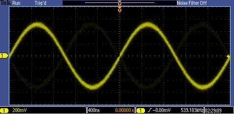
Below is an example of how this mode works. We generated a noisy sine waveform into oscilloscope. Due to this noise, we got the fuzzy waveform shown below.

By using the average acquisition mode function, we were able to get the clean waveform shown below on the same signal.

Math filter (FilterVu)
Some oscilloscopes offer post-processing filters which remove certain frequencies of noise from your signal. This gives you full control over which noise frequencies you want to filter out.
The Tektronix MSO/DPO2000B oscilloscopes offer this feature. FilterVu. as this feature is called, works as a variable low-pass filter and allows you to apply a low-pass filter frequency to the displayed acquisition.
Below is an example of its application. We generated a 10 kHz noisy sine waveform into the oscilloscope. Due to noise, the frequency measurement ranges from 6 kHz to 18 kHz.

By applying FilterVu and adjusting the variable noise filter frequency, the measured value is close to signal of interest as shown below.

Dealing with noisy signals and finding events of interest on your oscilloscope can be challenging. Fortunately, features like FilterVu and average acquisition mode go a long way toward getting noisy signals under control. To learn more, take a look at this application note on dealing with noisy signals and visit the MSO/DPO2000B oscilloscopes product page.