Introduction
Electric vehicles are breaking through into mainstream automotive sales with many governments and companies pledging full electric vehicle conversions in the 2020s. The limiting factor for these vehicles is a strong supply of safe, reliable, and highly efficient battery packs. Battery manufacturers are responsible for ensuring that every battery pack meets these tight standards while keeping volume high to meet increasing demands. Manufacturers must conduct a variety of mechanical and electrical tests that are performed throughout battery construction, using fast and accurate test and measurement solutions. One such solution is the Keithley 3706A System Switch and Multimeter paired with a 2460 or 2461 High Current Source Measure Unit (SMU) to conduct the busbar weld resistance test.
What is the Busbar Weld Resistance Test?
Battery packs contain many smaller modules, which are made up of even smaller cells as shown in Figure 1.
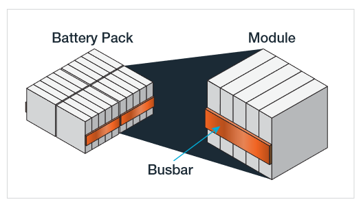
The cells within the modules are connected in parallel or series to achieve the desired voltage or current output. The cells are laser welded to a busbar, a long conductor that is isolated from ground. Busbars are useful for high current applications and for distribution of power from the battery. The current carried by the busbar could be up to several amps. Therefore, small resistances in the weld can generate enough heat to degrade the batteries and lead to early failures or unsafe operating conditions. The busbar weld resistance test characterizes the resistance of this weld. By measuring the resistance before the battery is complete, defective modules can be quickly removed from the line.
Measuring the Resistance of the Busbar Weld
If we consider the weld to the busbar to be a resistor, measuring the resistance is as simple as connecting a current source to the weld and measuring the voltage as shown in Figure 2.
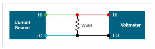
The resistance of the weld is then calculated using Ohm’s Law. The resistance of the weld is typically very low, on the order of milliohms to microohms. Therefore, it’s important that the current source is wired separately from the voltmeter. This is known as a 4-wire resistance measurement, and it is used when the device’s resistance is on the same order or lower than the resistance of the test leads. The voltmeter’s high resistance inputs force all of the current from the source across the load, ensuring that the measured voltage is across the load only and the calculated resistance does not include the test leads.
Speed and accuracy must be considered when choosing a current source and voltmeter for the circuit. The current source must be able to accurately source a large current, up to several amps, so that a measurable voltage is produced. The voltmeter should be able to accurately measure small voltages, so a 6.5-digit or 7.5-digit digital multimeter is a good solution. Most battery packs contain many welds that need to be tested. A multichannel digital multimeter can combine high accuracy with speed, using switch cards to characterize multiple welds without rewiring.
The Keithley Solution
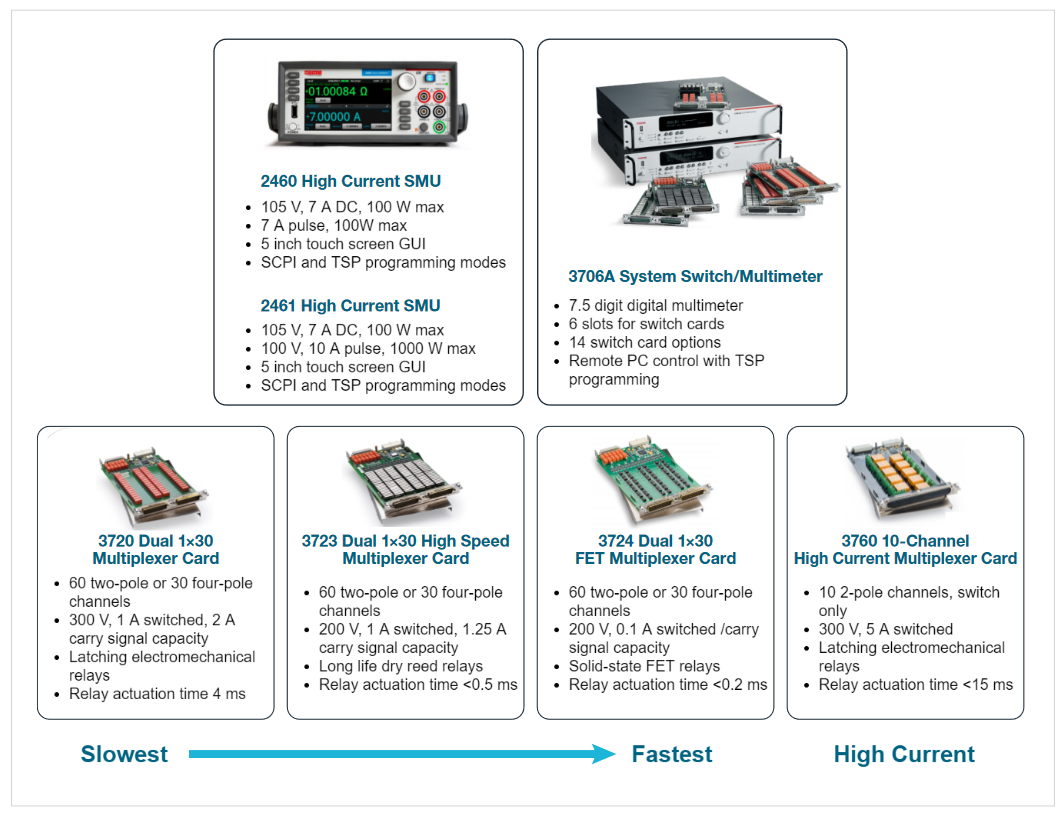
Characterizing the weld resistance can be made simple using the Keithley 2460 or 2461 High Current Source Measure Units and the 3706A System Switch and Multimeter. The 3706A mainframe has six slots that can be configured with 14 different plug-in modules. Density and switching speed are important for choosing a switch card, as is high current capability. Card options are shown in Figure 3.
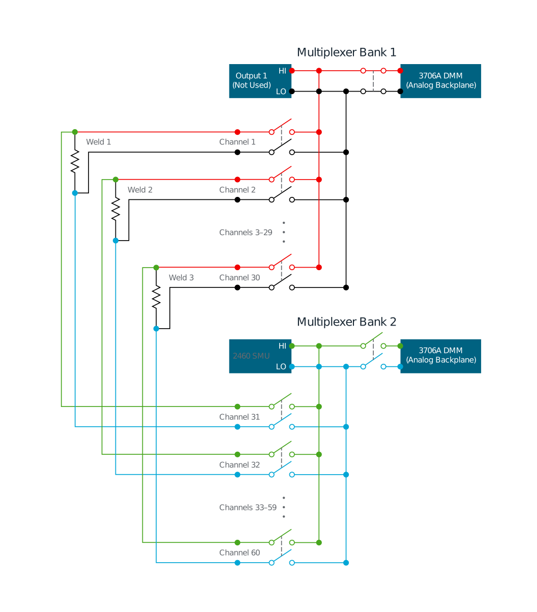
An example of a measurement configuration using the 3706A with one 3720 plug-in module is shown in Figure 4. The first multiplexer bank uses the internal DMM to measure the voltage, and the second multiplexer bank is connected to the 2460. One channel of each bank is connected to one weld. Therefore, a 3706A with six 3720 cards can test 180 welds without rewiring. For even more density, the SMU could be routed to the backplane of the 3706A, freeing up all 60 channels of the 3720 card to measure welds. The process of closing each channel to measure can be automated for speed and efficiency.
Conclusion
Safety and efficiency are top priorities for battery pack manufacturing. Testing at each point in the manufacturing process is critical to ensure the batteries meet the proper standards. Measurement solutions that are fast and accurate, such as the Keithley 2460 High Current Source Measure Unit and the 3706A Switch System and Multimeter, make running tests like the busbar weld test simple and reliable.
Find more valuable resources at TEK.COM
Copyright © Tektronix. All rights reserved. Tektronix products are covered by U.S. and foreign patents, issued and pending. Information in this publication supersedes that in all previously published material. Specification and price change privileges reserved. TEKTRONIX and TEK are registered trademarks of Tektronix, Inc. All other trade names referenced are the service marks, trademarks or registered trademarks of their respective companies.
060822 1KW-73821-1