Introduction
Arbitrary waveform generators are very flexible instruments capable of outputting voltage waveforms of virtually any shape. These instruments are quite useful because they provide a controlled method of recreating the varying signals that may be seen by a device after it is placed into a system. By recreating these signals, device designers can use them to test their devices. Unfortunately, arbitrary waveform generators typically cannot supply very much current and max out at just a few hundred milliamps. For many devices, this level of current is simply insufficient. To achieve higher currents, the arbitrary waveform generator can be combined with a power amplifier, but this requirement for additional hardware not only adds cost but increases the complexity of the test system. A much better solution would be a single box that can output both an arbitrary waveform and the additional current required by the device. One such instrument is the Source Measure Unit (SMU) instrument.
SMU instruments combine the capabilities of a precision DC power supply with the measurement capabilities of a highly accurate DMM. These instruments are most commonly used when a very precise current or voltage must be sourced and an accurate voltage or current measurement must be made. These instruments are used to characterize devices by sweeping voltage or current across the device and measuring the corresponding current or voltage. Because performing sweeps is so common, most of these instruments have sweep capabilities built right in, allowing the user to program the instrument to perform linear, logarithmic or list sweeps easily with a minimal number of commands. Although the linear sweep is certainly the most common type, the real power lies with the list sweep. In a list sweep, the user provides the value of every point in the sweep. This sweep type allows the SMU instrument to be used as an arbitrary waveform generator.
One test that requires arbitrary waveform capability but requires more current than an arbitrary waveform generator can provide is the CI 230 Power Cycling test as specified by the Ford EMC-CS-2009.1 specification. This test simulates the changes in supply voltage seen by the electrical and/or electronic components and subsystems of the automobile when the engine is being started. It specifies the use of four different waveforms, each being quite complex and including DC levels, step functions, ramp functions, and a 4Hz sine wave. The specifications for these waveforms can be seen in Figure 1.
The automobile components and subsystems tested often require several amps of current in order to function properly.

With arbitrary waveform capabilities and the ability to source up to 20A of DC current, SMU instruments are very capable for performing this test. This application note shows how to use Keithley Series 2600B and Series 2650A System SourceMeter SMU Instruments as arbitrary waveform generators to generate these complex waveforms.
Configuring the SMU for AWG Output
Configuring the Series 2600B and Series 2650A System SourceMeter SMU Instruments for arbitrary waveform output is very similar to configuring them for any normal list sweep. The major difference is that for arbitrary waveform output, a constant update rate is necessary for the source output, so some additional timing control is required. To set up the SMU instruments for arbitrary waveform output, take the following steps:
- Generate a waveform table
- Configure the SMU instrument for list sweeps
- Configure the trigger model timing
- (Optional) Configure measurements
Generate a Waveform Table
List sweeps in Series 2600B and Series 2650A System SourceMeter SMU Instruments use a table of values to define the points in the sweep. In order to get the SMU instrument to output a waveform, it’s first necessary to get the waveform into a table. These tables are defined using the native Lua scripting capabilities of these instruments’ Test Script Processors and can be created quickly with as little as one line of code.
<tableName> = {<point1>, <point2>, …, <pointN>}
In the example above, <tableName> is a new table variablethat was both declared and assigned this single line of code.<point1> through <pointN> are the values of the entries in the table. For example:
wfrmTbl = {2, 4, 6, 4, 2}
This line of code creates a table named wfrmTbl with five entries 2, 4, 6, 4, and 2. Alternatively, a table can be created in a loop and the values assigned one at a time. For example:
wfrmTbl = {} -- Declare an empty table variable
for i=1,10 do
wfrmTbl[i] = 2 * i -- Add an entry to the table
end
In this example, the code creates a table containing a linear ramp function from 2 to 20 over 10 points. By using a loop like this along with the math functions built into the Lua scripting language, it’s possible to generate tables that implement even more complex waveforms like sine waves, triangle waves,exponential rise and decays and more.
Unlike some SMU instruments where the number of points in a list sweep is limited to just 2500, the number of points in a list sweep on the Series 2600B and Series 2650A SourceMeter SMU Instruments is limited only by the amount of memory available on the instrument. With the large memory size that is standard on these instruments, they can easily handle multiple waveforms with hundreds of thousands of points, to create incredibly complex waveforms.
Configure the SMU Instrument for List Sweeps
To configure the SMU instrument for a list sweep, one must first configure the basic settings of the SMU instrument source.Follow these steps to configure the source:
- Configure the source function (Current or Voltage)
- Configure the sense mode (Local or Remote)
- Disable source auto ranging
- Set the source range
- Set the source limit
- Set source delay to 0
NOTE: Source auto ranging must be disabled and source delay set to 0 in order to ensure consistent timing between points.
Example Source Configuration
smua.source.func = smua.OUTPUT_DCVOLTS
smua.sense = smua.SENSE_LOCAL
smua.source.autorangev = smua.AUTORANGE_OFF
smua.source.rangev = 20
smua.source.limiti = 0.1
smua.source.delay = 0
Once the source has been configured, the sweep function of the SMU instrument can be set up. Using the table generated earlier, the list sweep function can be set up with the following lines of code.
smua.trigger.source.listv(wfrmTb) |
Tells the SMU to use the table wfrmTbl as the source list for the sweep. |
smua.trigger.count = table.getn(wfrmTbl) |
Sets the number of points for the trigger model to loop through during the sweep. This should be set to the same number as the number of points in the table in order to output the entire waveform. |
smua.trigger.endsweep.action = smua.SOURCE_HOL |
This setting tells the SMU what level to set the source after the sweep has completed. Setting it to smua.SOURCE _ HOLD tells the SMU to leave it at the same level as the last point in the sweep. Setting it to smua.SOURCE _ IDLE would tell it to return the source to the level it was at before the sweep was started. |
NOTE: By default, the trigger model will run through the sweep only once each time the trigger model is initiated. To make the SMU instrument output the sweep more than once, add the command smua.trigger.arm.count = <cycles> where <cycles> is the number of times to output the sweep. To output the sweep indefinitely, set the value to 0. Note that if the arm count is set to 0, it will be necessary to send the command smua.abort() to stop the output.
Configure the Trigger Model Timing
Iterating through the points of a sweep is controlled by the SMU instrument’s trigger model. By default, the trigger model of the Series 2600B and Series 2650A SourceMeter SMU Instruments will iterate through the sweep as quickly as possible. This can cause variability as well as an unknown in what the time is between the points. In order to function like an arbitrary waveform generator, the time between the points needs to be constant. This can be done by configuring a timer in the trigger model to trigger the source event.
Use the following line of code to configure Timer 1 to trigger the source event.
smua.trigger.source.stimulus = trigger.timer[1].EVENT_ID
The source event of the trigger model is the event where the output level gets updated. By forcing it to wait for an event from Timer 1 before it performs its action, it is possible to control the rate at which the output is updated. Next, it’s necessary to configure the timer to set the update interval. Use the following lines of code to configure Timer 1.
trigger.timer[1].delay = 125e-6 |
This sets the interval at which the timer generates events. A value of 125µs provides a source update rate of 8,000 points per second.Values a low as 50µs can be used if all the points in the waveform are of the same polarity (all positive or all negative). If the waveform contains changes in polarity, values of 125µs or greater are recommended. |
trigger.timer[1].count = table.getn(wfrmTbl) - 1 |
This sets the number of times the timer will count down and generate an event before it stops. This should be set to the number of points in the sweep minus 1. The first point in the sweep will be triggered when the timer is triggered because the timer will pass this trigger through. |
trigger.timer[1].passthrough = true |
This sets whether to pass the trigger event that started the timer through to the timer’s output or not. If set to true an event will be generated by the timer immediately after the timer itself is triggered. If set to false the timer will not generate its first event until the timer has finished counting down for the first time. |
trigger.timer[1].stimulus = smua.trigger.ARMED_EVENT_ID |
This sets the event that triggers the timer to start. Using the smua.trigger.ARMED _ EVENT _ ID will cause the timer to start counting down as soon as the SMU trigger model is armed and enters the trigger layer.This happens automatically after the trigger model is initiated if no wait events have been configured. Output of the sweep can be forced to wait for an event such as a digital I/O trigger or a front panel key press by assigning the timer’s stimulus to one of these other events’ event id. |
Configure Measurements
Unlike an arbitrary waveform generator, an SMU instrument is capable of not only sourcing an arbitrary waveform but also measuring it. Being able to measure in addition to source allows the power the DUT consumes to be tested. In order to add measurements to the SMU instrument’s arbitrary waveform output, we must perform some configuration first. If we simply enabled the measurements, we would find that our arbitrary waveform output would no longer have the same timing between points and each point in the waveform would be extended by the amount of time required to take the measurement. In order to avoid affecting the source output, we must configure the measurements to fit within the time in between source points.
Several settings in the SMU instrument affect the amount of time a measurement takes. To make the measurements fit within the source update interval, do the following:
- Turn off auto ranging
- Turn off auto-zero
- Reduce the measure delay
- Reduce the NPLC setting
- Account for measurement overhead
Turn off Auto Ranging and Auto-Zero
Auto ranging and auto-zero introduce variability in the time required to acquire a measurement and should be turned off
Reduce the Measure Delay
The measure delay is the amount of time that the SMU instrument waits after the measurement is triggered before the analog-to-digital converter (ADC) starts the conversion. By default, the measurement is triggered immediately after the source event has completed; therefore, measure delay sets the time from when the source updates to the time when the analogto-digital conversion starts. When using the SMU instrument as an arbitrary waveform generator, the optimal value for measure delay places the start of the conversion as close to the end of the source update interval as possible without extending the interval. The optimal value can be calculated as follows.
Measure Delay = Source Interval – (Conversion Time + Overhead)
Source Interval is the time between updates of the source output as configured previously using Timer 1. Conversion Time is the time required for the ADC to perform the conversion and is affected directly by the NPLC value. Overhead is the time associated with processing and storing the result of the analogto-digital conversion.
Reduce the NPLC Setting
The Number of Power Line Cycles (NPLC) setting adjusts the number of power line cycles over which the ADC performs the conversion and directly affects how long the measurement will take. By default, the NPLC value is set to 1, which means the analog-to-digital conversion will be performed over one power line cycle or 16.67ms for 60Hz power. By reducing the NPLC value, the amount of time the conversion takes is reduced. For example, reducing the NPLC value to 0.001 reduces the conversion time down to 16.67µs (16.67ms * 0.001 = 16.67µs). The NPLC setting should be made small enough such that the conversion time plus measure delay plus the associated measurement overhead is less than or equal to the source update interval.
NOTE: Reducing the NPLC reduces the ADC’s ability to reject noise and therefore results in a nosier measurement.
Account for Measurement Overhead
Associated with every measurement is some overhead for the system to process the result of the analog-to-digital conversion and move it into memory. This is the overhead described in the equations in the previous sections. This overhead can vary between 20µs and 50µs and must be accounted for to ensure that the measurement does not affect the source interval. To be safe, a value of 60µs should be assumed for measurement overhead and used in the equations.
Running the Sweep
Once the SMU instrument has been configured, outputting the arbitrary waveform is very simple; turn the output on and initiate the trigger model. To do this, simply send the following commands:
smua.source.output = smua.OUTPUT_ON smua.trigger.initiate()
If the trigger stimulus for Timer 1 was configured for the SMU instrument’s armed event, then the waveform output will start right away; otherwise, the output will wait until the configured trigger stimulus is received.
Using the Included Script
Appendix A of this application note includes a script that can be loaded onto the Series 2600B and Series 2650A System SourceMeter SMU Instruments that makes generating arbitrary waveforms on these SMU instruments easy. (See the instruments’ reference manuals for details on loading and running scripts.) After loading and running the script, arbitrary waveform generation can be configured and run by simply calling a few functions from the script. For example, after loading and running the script, outputting a sine wave can be done by sending the following commands to the instrument:
SetupSineFunction(100, 4, 2, 0.1, false, nil) RunAWG()
AWG waveforms (sine, square, ramp, pulse and noise) and the EMC-CS-2009.1 CI 230 waveforms, as well as a function for loading a waveform from a CSV file located on the USB thumb drive plugged into the instrument’s front panel. The following functions are available for use from this script.
- SetupAWG()
- SetupSineFunction()
- SetupSquareFunction()
- SetupRampFunction()
- SetupPulseFunction()
- SetupNoiseFunction()
- RunAWG()
- StopAWG()
- ReadWaveformFromFile()
- GenerateCI230WaveformA()
- GenerateCI230WaveformB()
- GenerateCI230WaveformC()
- GenerateCI230WaveformD()
Documentation for these functions is included within the comments of the code.
NOTE: Although the included script is capable of generating the square and pulse waveforms, the built-in pulse functions of the Series 2600B and Series 2650A System SourceMeter SMU Instruments are better suited for generating these functions. See the instruments’ reference manuals for details.
Generating EMC-CS-2009.1 CI 230 Waveforms
The script included in this application note contains functions that create waveform tables for the four EMC-CS-2009.1 CI 230 waveforms. Each of these complex waveforms is 11.1 seconds long. With a source update interval of 125µs, 88,800 points are required to implement each of these waveforms. Creating these points manually by listing each and every one out by hand would take an extremely long time. Instead, the functions in this script use the power of Keithley’s Test Script Processor to generate the points programmatically by breaking the waveform into multiple segments. The number of points in each segment is calculated, then these points are processed in a loop to produce the output value for each point. This approach saves time and reduces error by eliminating the need to list out these points individually.
The following lines of code demonstrate how to use these functions to generate the CI 230 waveforms and save each one in its own table.
wfrmA = {}
wfrmB = {}
wfrmC = {}
wfrmD = {}
GenerateCI230WaveformA(wfrmA)
GenerateCI230WaveformB(wfrmB)
GenerateCI230WaveformC(wfrmC)
GenerateCI230WaveformD(wfrmD)
The first four lines create table variables in which to store the waveforms. The second four lines create the waveforms and store them in the tables. Once the waveform tables have been generated, outputting any one waveform requires only two lines of code. For example, to output CI 230 Waveform C, use the following lines of code.
SetupAWG(0, 20, 0.1, wfrmC, false, nil)RunAWG()
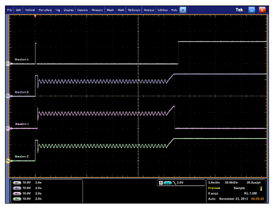
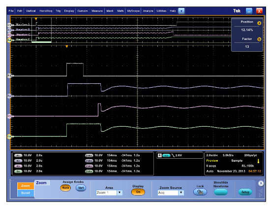
This first line sets the SMU instrument up for arbitrary waveform output using the table created earlier as the source for the waveform. The second line starts the output. Figure 2 is a scope shot capturing the output of the four waveforms from a Model 2612B System SourceMeter SMU Instrument. Figure 3 and Figure 4 are close-up views of the start and end of these waveform outputs.

Conclusion
Arbitrary waveform generators are very powerful tools because they allow sourcing a waveform of any shape. However, they are designed for use with small, low power devices and cannot deliver the current required by larger devices or systems. SMUs are very versatile instruments that can provide arbitrary waveform capabilities as well as the current required by larger devices and systems. With the ability to supply as much as 20A and 200W of DC power, SMU instruments like the Model 2651A High Power SourceMeter Instrument are capable of testing even the most demanding devices. SMU instruments provide the ability to measure as well as source, so in addition to testing devices with arbitrary waveforms, they allow monitoring the device’s current consumption. This provides engineers with more insight into what their device under test is doing and is incredibly useful for diagnosis when things go wrong. Using SMUs, more detailed testing can be performed on devices, resulting in more robust and reliable designs.