By Christopher Skach
Editor’s Note: This 5-part series of posts will walk you through the fundamentals of radar test and measurement. Here’s the lineup
- Part 1: Radar basics, including continuous and pulsed radar, with a deeper dive into pulsed radar.
- Part 2: Lifecycle of radar measurement tasks, including key challenges in verification and production testing as well as a look at transmitter and receiver tests.
- Part 3: Analysis of radar signals including measurement methods and test setups.
- Part 4: Creating signals that look real to radar.
- Part 5: Tools for measuring modern radar systems.
Generating radar signals is one of the most challenging tasks for a signal generator. The signals’ combination of carrier frequency, modulation bandwidth, and, in most cases, their pulsed nature creates a series of requirements that can be difficult to match efficiently. The need to emulate multi-antenna radar systems based on phased array antennas or more recently, MIMO architectures, makes it necessary to generate multiple signals with tightly controlled timing and phase alignments.
Traditionally, radar signal generation has been implemented with a baseband signal generator and an RF/μW modulator. However, the Tektronix AWG70000 Series Arbitrary Waveform Generator (AWG) delivers sampling rates up to 50GS/s with 10-bit vertical resolution, 20 GHz usable bandwidth, 16-GSample waveform memory and excellent SFDR (Spurious Free Dynamic Range) characteristics. This level of performance allows for the direct generation of the fully-modulated RF/μW signals required by modern radar. Most of these requirements are impossible to meet with lower-performance AWGs or traditional vector signal generators (VSG).
This use of the AWG70000 series offers higher signal quality, cost-effectiveness, and more repeatability than traditional options. AWGs can generate radar signals through three basic methods:
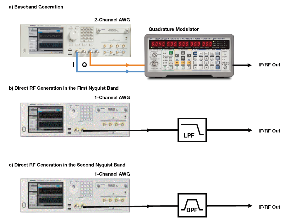
Baseband generation -- The AWG generates a time-domain signal to be applied to an RF modulator. For simple signals, a one-channel AWG output is applied to an amplitude modulator (AM). For more complex signals with complex digital modulation or fast frequency sweeps (chirp) both the amplitude and the phase of the carrier must be instantaneously controlled. In this case, the easiest and most flexible solution is a quadrature modulator with two baseband signals.
IF (Intermediate Frequency) generation – The AWG generates a modulated signal at a relatively low carrier frequency. Often the signal can be applied directly to a signal- processing block in the receiver or transmitter. In situations involving the final RF/μW frequency it an up-converter block is needed to reach the final carrier frequency.
Direct RF generation -- The AWG generates the modulated carrier at the final RF/μW frequency. No additional signal-processing blocks aside from the normal filters or amplifiers are required.
Each of these methods has pluses and minuses.
For most baseband and IF signals, AWGs with a sample rate of a few GS/s is sufficient, but the modulation bandwidth of the final RF/μW signal will be limited by the modulator or up-converter and wideband quadrature modulation is sensitive to I/Q imbalance or quadrature errors. Accurate alignment after careful calibration is required to produce signals of adequate quality.
Direct signal generation requires an extremely fast AWG such as the AWG7000 with a sample rate at least 2.5 times higher than the maximum frequency component of the signal, speeds that are now possible with the latest generation of Tektronix AWGs that can deliver quality signal generation beyond the Ku band (12-18GHz).
Baseband Signal Generation
AWGs can generate both undistorted or distorted signals. Deliberate distortion can compensate for external distortion to improve flatness and group delay response. Such compensation takes the form of a pre-emphasis filter to correct the generation system’s overall low-pass frequency response. As high frequency components are boosted, the low-frequency components of the signal must be attenuated to maintain a peak-to- peak value that fits within the available DAC dynamic range.
An AWG’s maximum sampling rate greatly influences signal quality. It is good practice to set the AWG sampling rate well over the minimum Nyquist requirement for a given signal. This oversampling increases signal quality for various reasons including flatter frequency response, image rejection, lower quantization noise and lower pulse-to-pulse jitter. In fact, the main drawback to oversampling is the need for more memory – a reason why long record lengths are important to high-speed AWGs. The AWG70000 with its 16 GSample waveform memory can generate at 50GS/s almost twice the time window that competing instruments running at 12GS/s can create with their 2 GSample waveform memory.
Signal simulation
When a radar subsystem is being designed the rest of the system is often unavailable. By using off-the-shelf, general- purpose test equipment to simulate other subsystems the device under test can be tested under controlled signal conditions.
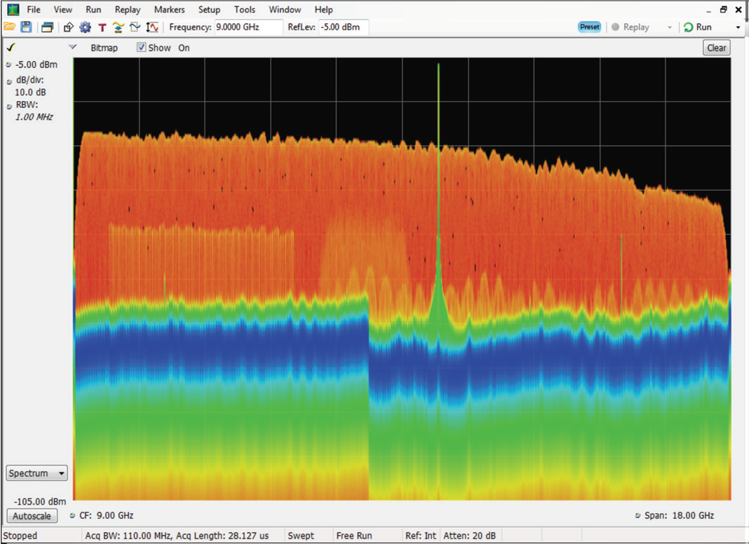
A cluttered open-air environment can be simulated using a wide-band AWG such as that below. The various signals such as wide- and narrow-band chirp (LFM), narrowband, CW and frequency-hopped radar signals were captured by a real-time spectrum analyzer. Several communication signals and other interferers can also be seen in the same frequency bands as the radar signals.

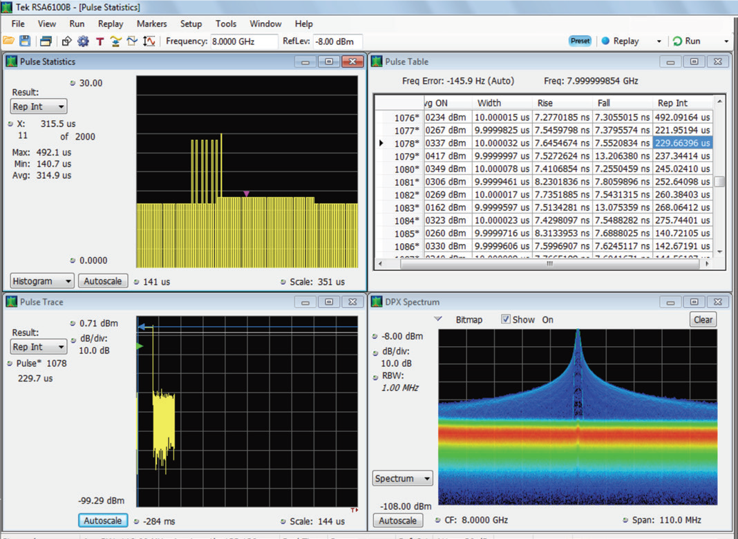
Radar transmitter testing includes extensive evaluation of a wide variety of test signals. In many cases the evaluation includes 100s or 1,000s of pulses that are then evaluated using statistical techniques. The test result shown in the screen below evaluates PRI on a set of 2,000 pulses constructed as a staggered PRI CW pulse waveform on an AWG. The histogram provides a statistical view of the distribution of the PRI measurements, while the pulse table and pulse waveform can be used to view measurements for each individual pulse.
Direct Carrier Generation
Ideal AWGs can produce any signal from DC up to half the sampling rate (Fmax = Fs/2). With a high enough sampling rate, it is possible to directly generate a modulated RF signal. Previously, relatively low sampling rate and poor spurious-free dynamic range (SFDR) limited highspeed AWGs to generating carriers of only a few GHz.
Direct generation offers advantages over the traditional baseband/ external modulator combination including:
- Baseband generation and quadrature modulation are performed mathematically.
- No additional equipment is required.
- A single AWG can generate multiple dissimilar carriers or wideband noise so more realistic test scenarios can be obtained with a single instrument.
- Simplified calibration procedure.
Although these advantages are significant, actual implementations of this architecture can show some drawbacks as well. One important issue is record length requirements. For a given record length (RL), the maximum time window (TW = RL/Fs) that can be implemented is inversely proportional to sampling rate (Fs). Since sampling rates for direct RF generation need to be higher than those for baseband signal generation, the same record length translates to shorter achievable time-windows.
Record length is crucial for a realistic emulation of complex radar systems incorporating staggered pulse sequences, frequency hopping patterns or time varying echo characteristics caused by target movement or antenna vibration.
Wideband signals may also need some linear distortion to compensate for flatness and phase linearity issues, including those created by cabling and interconnections, over high bandwidth. Applying corrections based only on the amplitude response improves modulation quality performance although phase response compensation is also required for optimal performance. Direct carrier generation also requires excellent sampling clock jitter performance because this translates directly to phase noise in the generated carriers.
Some applications, such as MIMO radar generation, require multiple channels. All the channels involved must be synchronized, so they must share the same sampling clock, and be time-aligned. Any timing difference or channel-to- channel jitter will result in a reduced quality signal. When more than one instrument must be synchronized, standardized synchronization methodologies and appropriate firmware such as those available for the AWG70000 series generators can greatly simplify the alignment tasks and dramatically improve repeatability and reliability.
To recap, the latest Tektronix AWGs allow for the direct generation of complex radar signals up to a final carrier frequency of 20GHz. This capacity is made possible by recent breakthroughs in DAC conversion performance. Even the most complex frequency-agile or MIMO radar systems can now be emulated through direct RF generation coupled with deep waveform memory and time alignment between channels within a single generator or across multiple synchronized units. For a deeper discussion on radar signal generation, you’ll want to download the Creating Signal That Look Real to Radar application note.