與我們聯絡
與 Tek 業務代表即時對談。 上班時間:上午 6:00 - 下午 4:30 (太平洋時間)
請致電
與 Tek 業務代表即時對談。 上班時間:上午 8:30 - 下午 5:30 (太平洋時間)
下載
下載手冊、產品規格表、軟體等等:
意見回饋
RM4 Rackmount Kit Instructions
This document supports Tektronix 4 Series MSO instruments (MSO44, MSO46, MSO44B, MSO46B). The rackmount kit is a collection of parts that, once installed, configure the instrument for mounting into a standard 19-inch equipment rack.
此手冊適用於:
MSO44, MSO46, MSO44B, MSO46B
By downloading, you agree to the terms and conditions of the Manuals Download Agreement.
Manuals Download Agreement
ATTENTION: please read the following terms and conditions carefully before downloading any documents from this website. By downloading manuals from Tektronix' website, you agree to the following terms and conditions:
Manuals for Products That Are Currently Supported:
Tektronix hereby grants permission and license to owners of Tektronix instruments to download and reproduce the manuals on this website for their own internal or personal use. Manuals for currently supported products may not be reproduced for distribution to others unless specifically authorized in writing by Tektronix, Inc.
A Tektronix manual may have been revised to reflect changes made to the product during its manufacturing life. Thus, different versions of a manual may exist for any given product. Care should be taken to ensure that one obtains the proper manual version for a specific product serial number.
Manuals for Products That Are No Longer Supported:
Tektronix cannot provide manuals for measurement products that are no longer eligible for long term support. Tektronix hereby grants permission and license for others to reproduce and distribute copies of any Tektronix measurement product manual, including user manuals, operator's manuals, service manuals, and the like, that (a) have a Tektronix Part Number and (b) are for a measurement product that is no longer supported by Tektronix.
A Tektronix manual may be revised to reflect changes made to the product during its manufacturing life. Thus, different versions of a manual may exist for any given product. Care should be taken to ensure that one obtains the proper manual version for a specific product serial number.
This permission and license does not apply to any manual or other publication that is still available from Tektronix, or to any manual or other publication for a video production product or a color printer product.
Disclaimer:
Tektronix does not warrant the accuracy or completeness of the information, text, graphics, schematics, parts lists, or other material contained within any measurement product manual or other publication that is not supplied by Tektronix or that is produced or distributed in accordance with the permission and license set forth above.
Tektronix may make changes to the content of this website or to its products at any time without notice.
Limitation of Liability:
TEKTRONIX SHALL NOT BE LIABLE FOR ANY DAMAGES WHATSOEVER (INCLUDING, WITHOUT LIMITATION, ANY CONSEQUENTIAL OR INCIDENTAL DAMAGES, DAMAGES FOR LOSS OF PROFITS, BUSINESS INTERRUPTION, OR FOR INFRINGEMENT OF INTELLECTUAL PROPERTY) ARISING OUT OF THE USE OF ANY MEASUREMENT PRODUCT MANUAL OR OTHER PUBLICATION PRODUCED OR DISTRIBUTED IN ACCORDANCE WITH THE PERMISSION AND LICENSE SET FORTH ABOVE.
Read Online
Kit description
This document supports Tektronix 4 Series MSO instruments. The rackmount kit is a collection of parts that, once installed, configure the instrument for mounting into a standard 19-inch equipment rack.
For warranty information visit tek.com/warranty-status-search.
Products
This rackmount kit supports all 4 Series MSO instruments.
Minimum tool and equipment list
| Required tools and equipment | Part number |
|---|---|
| Screwdriver, Phillips, #2 | Standard tool |
| Wrench, 3/8" | Standard tool |
| Screwdriver, T-20 Torx | Standard tool |
| Screwdriver, T-10 Torx | Standard tool |
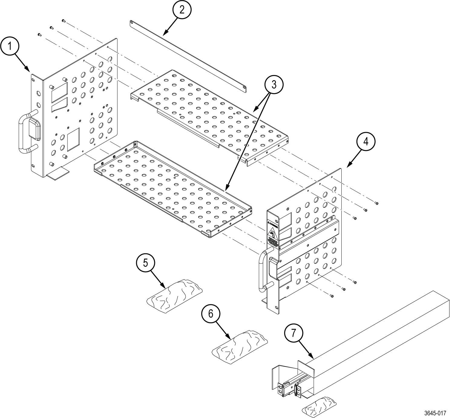
Kit parts lists
The following tables list the parts for the RM4 rackmount kit; not all of the parts will be needed for your instrument setup.
| Item | Quantity | Part number | Description |
|---|---|---|---|
| ----- | 1 each | 071-3645-xx | RM4 RACK MOUNT KIT INSTRUCTIONS |
| 1 | 1 | 441-2922-xx | BRACKET, LEFT, RACKMOUNT KIT |
| 2 | 1 | 407-6190-xx | FRONT FILLER PLATE, RACKMOUNT KIT |
| 3 | 2 | 407-6188-xx | BRACKET, TOP AND BOTTOM RACKMOUNT KIT |
| 4 | 1 | 441-2923-xx | BRACKET, RIGHT, RACKMOUNT KIT |
| 5 | 1 | 016-2142-xx | KIT, HARDWARE RACKMOUNT KIT This kit includes the hardware required to assemble the rackmount kit and attach it to the instrument. See Table 2 for the hardware list |
| 6 | 1 | 016-2116-xx | KIT, HARDWARE RACKMOUNT KIT This kit includes the hardware required to mount the assembled instrument and rack kit to the instrument rack. See Table 3 for the hardware list |
| 7 | 1 | 351-1095-00 | SLIDE ASSY; PAIR, W/STD HARDWARE KIT AND REAR BRACKET, SAFETY CONTROLLED |
| Item | Quantity | Part number | Description |
|---|---|---|---|
| H1 | 12 | 211-1584-xx | SCREW, MACHINE, M3X0.5X6MM PAN HEAD, TORX T10 |
| H2 | 8 | 211-1694-xx | SCREW, MACHINE, M4X0.7X16MM PAN HEAD, TORX T20 |
| H3 | 6 | 211-1695-xx | SCREW, MACHINE, M4X0.7X6MM PAN HEAD, TORX T20 |
| Item | Quantity | Part number | Description |
|---|---|---|---|
| H4 | 14 | 210-0833-xx | WASHER, RECESSED; 0.42 ID X 0.112 THK, STL NI PLATED, 0.588 OD |
| H5 | 14 | 210-1061-xx | WASHER, FLAT; 0.203 ID X 0.625 OD X 0.062, ZINC PLATED STEEL |
| H6 | 14 | 210-1548-xx | WASHER, FLAT 12 OD X 6.4 ID X 1.6THK |
| H7 | 14 | 211-1218-xx | SCREW, M6 X 16MM OVAL HEAD, PHILLIPS |
| H8 | 14 | 211-1219-xx | SCREW, M5 X 16MM OVAL HEAD, PHILLIPS |
| H9 | 14 | 212-0591-xx | SCREW, MACHINE; 10-32X.750 OVAL HEAD, POZI |
| H10 | 14 | 213-0199-xx | SCREW, MACHINE; 12-24 X 0.75, OVH, STL NP, POZ |
Warranted characteristics
When the instrument is installed according to the instructions in this document, the rackmounted instrument meets all warranted requirements listed in the instrument specification. Instruments mounted using methods other than those described in these instructions might not meet their warranted requirements.
For tables of the warranted characteristics, see Specifications in the specification and performance verification manual that applies to your instrument model.
 | CAUTION:The rack is more susceptible to tipping when the instrument is installed. To prevent the rack from tipping, ensure that the rack is stable before accessing rear panel of the instrument. Do not leave the instrument extended in the rack. |
The ambient temperature inside the instrument rack will vary depending on the location of the instrument within the instrument rack. Tektronix recommends that you measure the ambient temperature in the desired rack location before you install the instrument to ensure the operating temperature does not exceed the rated ambient temperature limit. If necessary, refer to the Environmental Specifications in your product documentation for the operating temperature limits.
| CAUTION:The instrument might be damaged due to overheating. When installing multiple instruments in an instrument rack, the ambient temperature may go up. You assume the responsibility to provide adequate cooling to meet the ambient temperature requirements listed in the specifications. |
Clearance requirements
The rack in which the individual instrument is mounted must provide the following clearance requirements:
- At least 310 mm (12.25 in) of vertical space or 7 RU (rack units) of vertical space
- A minimum width of 488 mm (19.2 in) between the left- and right-front rails in the rack. If possible, consider allowing at least 50.8 mm (2.0 in) on the right side and rear of the instrument for adequate airflow.
- A minimum inside depth of at least 254 mm (10 in) depth (from rack mounting ear to back of instrument). Airflow enters from the back of the instrument and exits on the right of the instrument when viewed from the front.
| CAUTION:Adhering to these requirements mounts the rack-adapted instrument with enough clearance for air circulation and accommodation of the power cord and mounting hardware. Failure to provide these clearances can result in overheating and can cause the instrument to operate improperly or fail. |
Important safety information
This manual contains information and warnings that must be followed by the user for safe operation and to keep the product in a safe condition.
To safely perform service on this product, see the Service safety summary that follows the General safety summary.
Service safety summary
The Service safety summary section contains additional information required to safely perform service on the product. Only qualified personnel should perform service procedures. Read this Service safety summary and the General safety summary before performing any service procedures.
To avoid electric shock
Do not touch exposed connections.
Do not service alone
Do not perform internal service or adjustments of this product unless another person capable of rendering first aid and resuscitation is present.
Disconnect power
To avoid electric shock, switch off the product power and disconnect the power cord from the mains power before removing any covers or panels, or opening the case for servicing.
Use care when servicing with power on
Dangerous voltages or currents may exist in this product. Disconnect power, remove battery (if applicable), and disconnect test leads before removing protective panels, soldering, or replacing components.
Verify safety after repair
Always recheck ground continuity and mains dielectric strength after performing a repair.
Terms in this manual
These terms may appear in this manual:
| WARNING:Warning statements identify conditions or practices that could result in injury or loss of life. |
| CAUTION:Caution statements identify conditions or practices that could result in damage to this product or other property. |
Installation instructions
These instructions are for qualified service personnel who are familiar with servicing the product. To avoid personal injury, do not perform any servicing unless you are qualified to do so. If you need further details for disassembling or reassembling the product, refer to the appropriate product manual. Contact your nearest Tektronix, Inc., Service Center or Tektronix Factory Service for installation assistance.
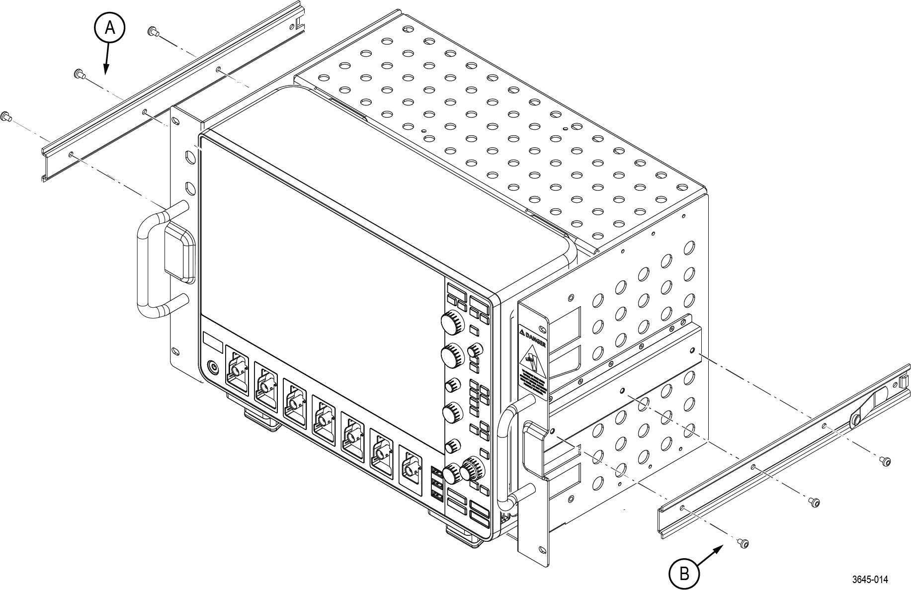
Assemble the rack mount on the instrument
Item numbers referenced in the assembly steps refer to the parts list in Table 1 and Table 2.
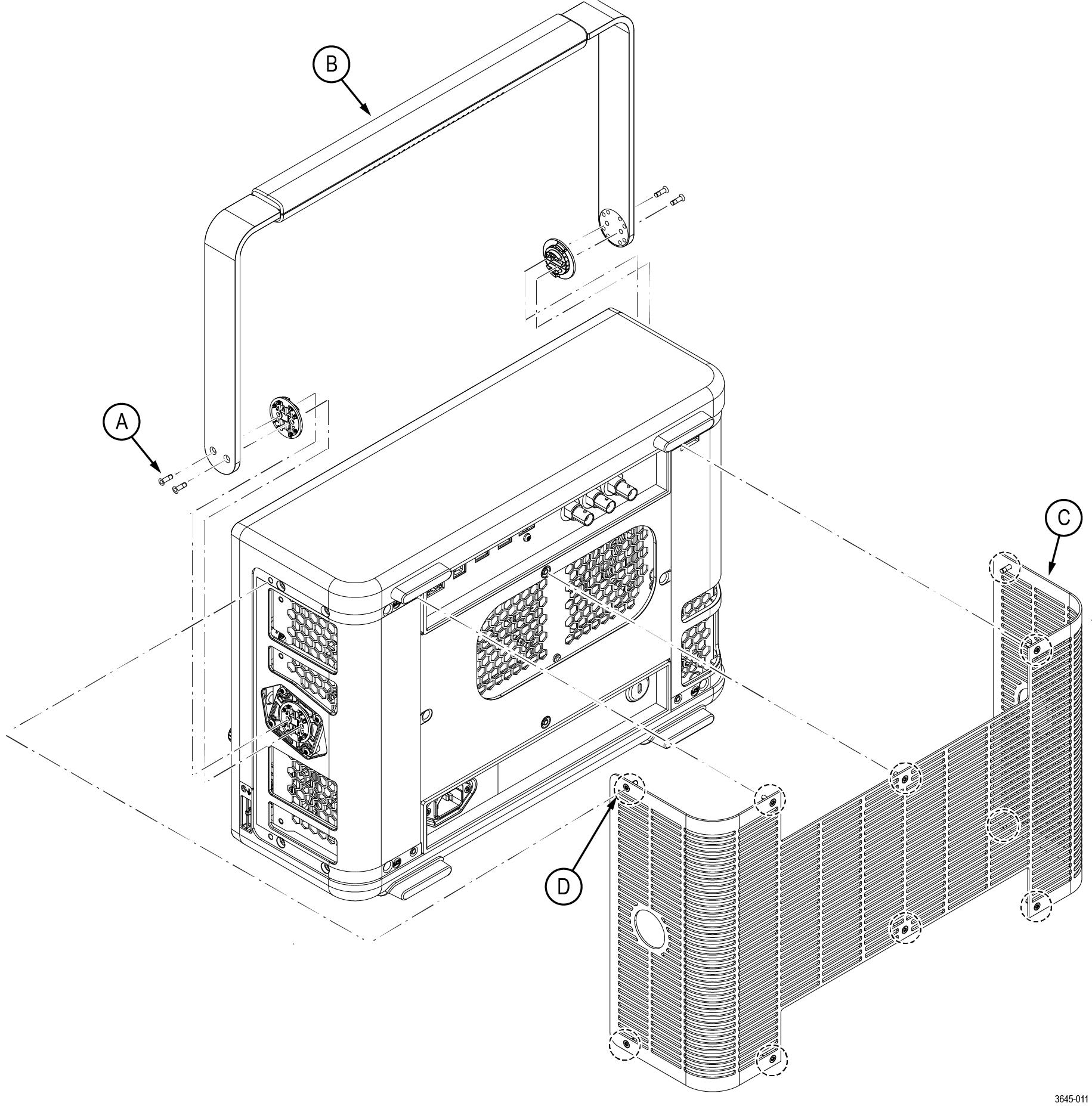
- Remove the instrument handle, hubs, and grill. Save the parts and hardware for future use.
- Remove the four TORX T10 screws from the handle.
- Remove the handle and the two handle hub couplers from the instrument.
- Remove the ten TORX T10 screws from the grill.
- Remove the grill from the back of instrument.
Figure 1. Prepare the instrument 
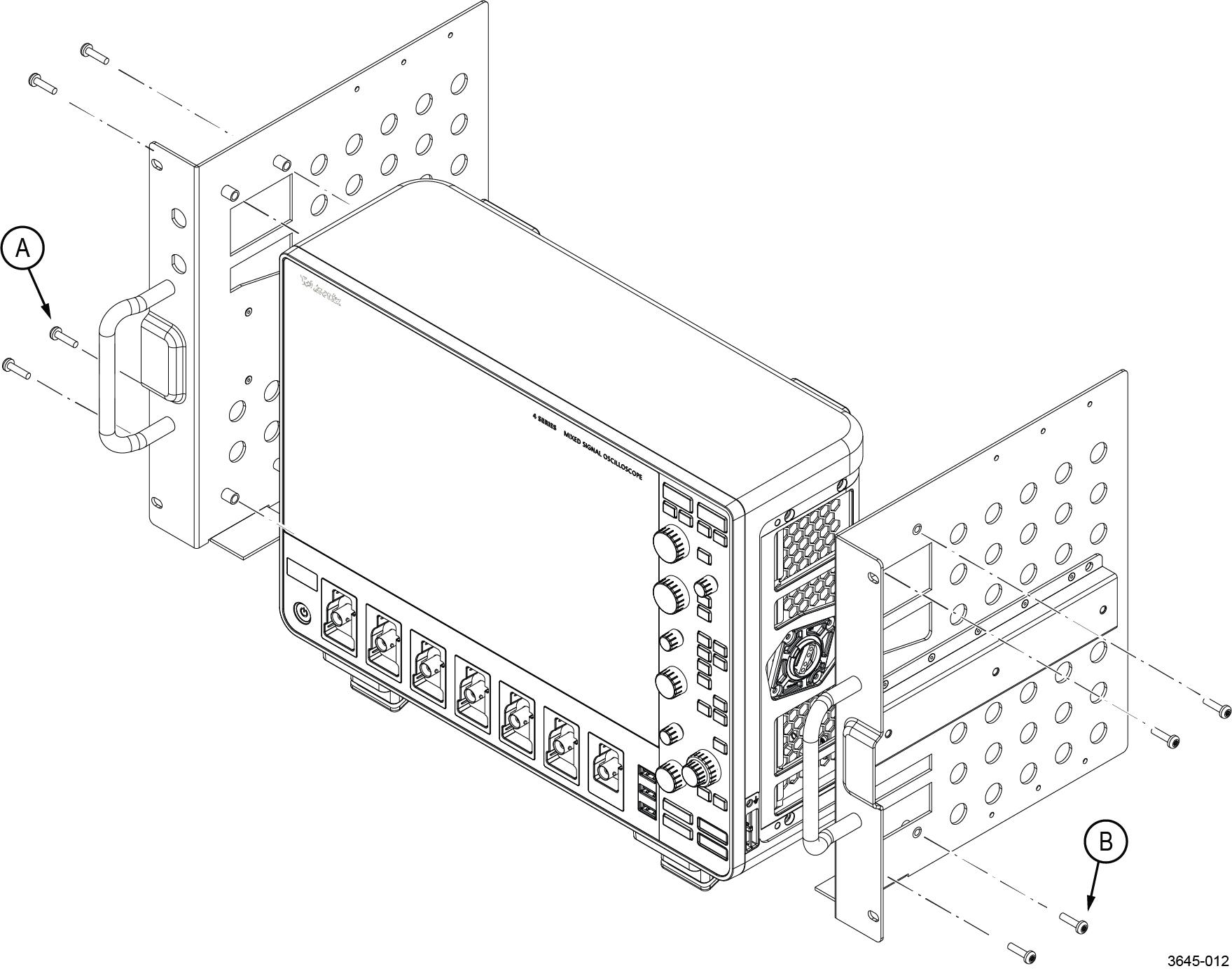
- Install the left and right mounting plates.
- Use four TORX T20 screws (item H2) to install the left mounting plate (item 1) to the instrument.
- Use four TORX T20 screws (item H2) to install the right mounting plate (item 2) to the instrument.
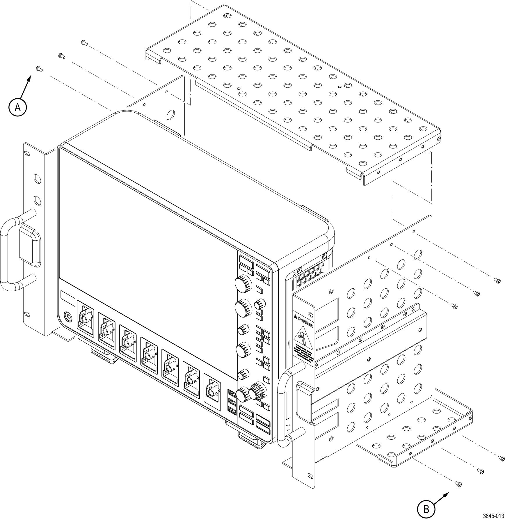
Figure 2. Mounting plate installation - Install the top and bottom support plates.
- Use six TORX T10 screws (item H1) to install the top support plate (item 3) to the mounting plates.
- Use six TORX T10 screws (item H1) to install the bottom support plate (item 3) to the mounting plates.
Figure 3. Support plate installation - Install the left-side and right-side slide mounts.
- Use three TORX T20 screws (item H3) to install the instrument-side portion of the slide (item 6) to the right mounting plate.
- Use three TORX T20 screws (item H3) to install the instrument-side portion of the slide (item 6) to the left mounting plate.
Figure 4. Slide mount installation
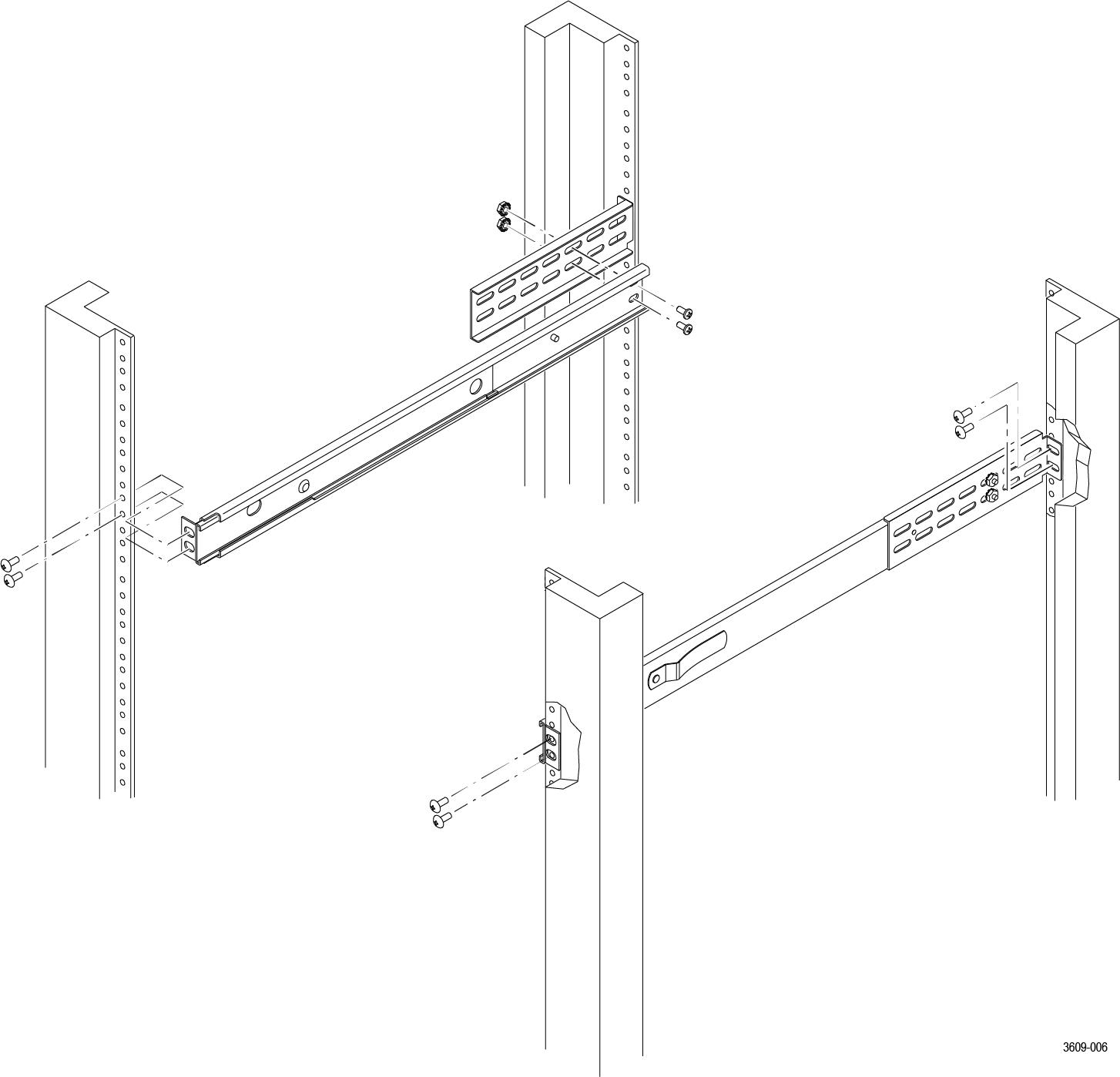
Install the instrument into the rack
- Use the hardware from Table 3 to install the rack slides in your equipment rack.
Figure 1. Installing the rail slides - Install the instrument in your equipment rack by inserting the rack mounts into the slides.
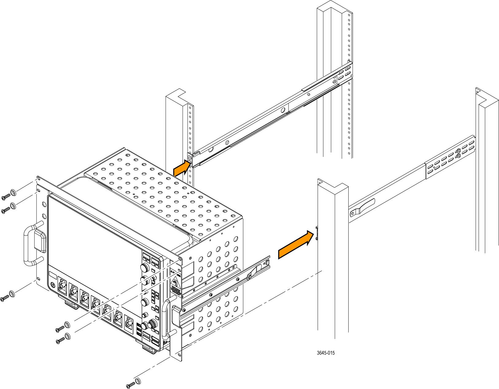
Figure 2. Installation of rack mounted instrument assembly into a rack WARNING:To avoid personal injury and prevent the instrument from tipping or dropping, use two or more people to install this instrument into the rack cabinet. After completing the installation procedure, verify that the instrument and the rack cabinet will not tip forward while the instrument is in the extended position. Do not leave the instrument extended when finished accessing the instrument. - Install the power cord. Provide access to a power plug or mains disconnect switch for turning the instrument on/off.
- Optionally install any cables you need connected to the instrument rear panel.
- Slide the instrument into the equipment rack, and secure the instrument to the rack using standard rack hardware.
- Install the front filler plate on the rack above the instrument using standard rack hardware.
Front panel dimensions
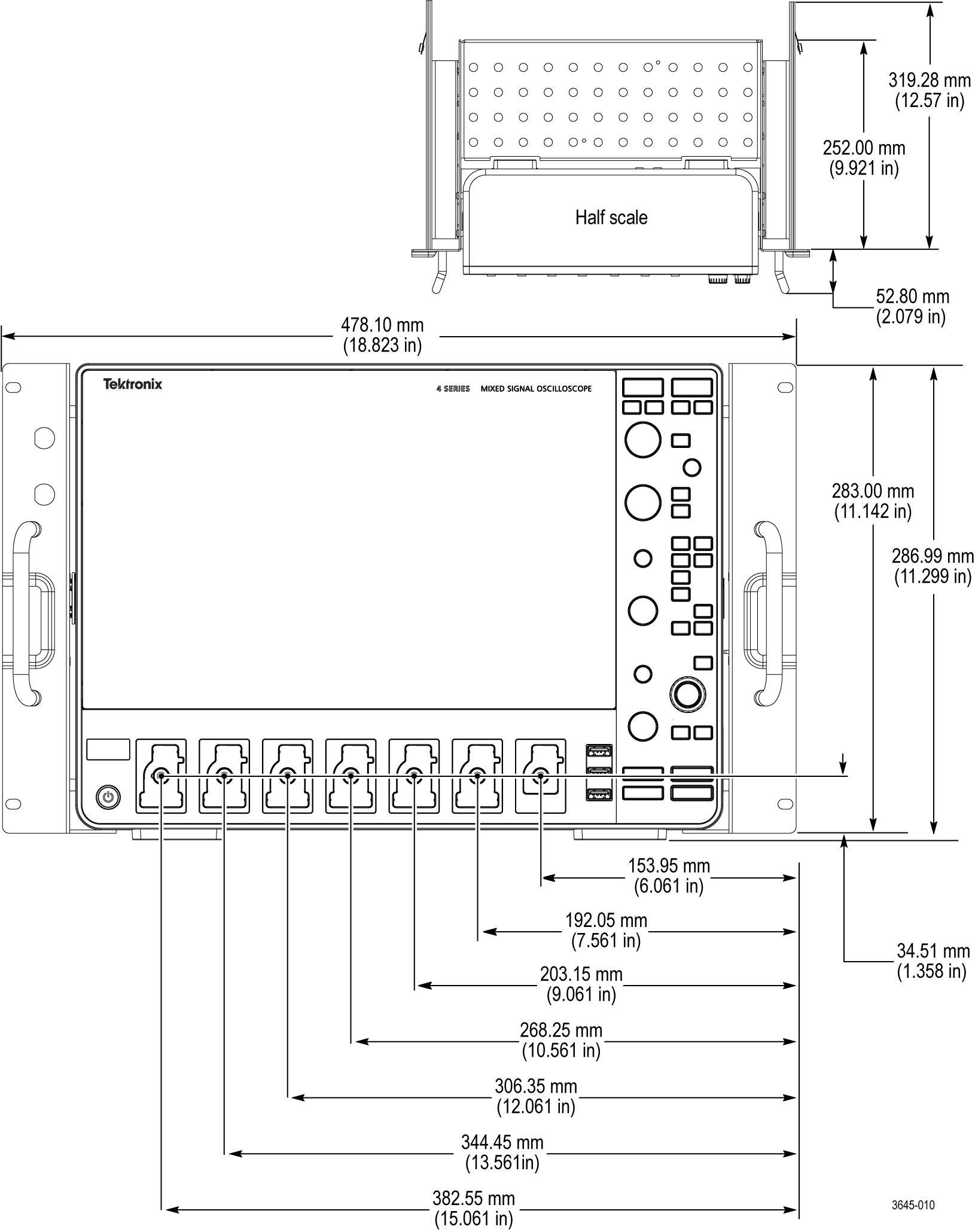
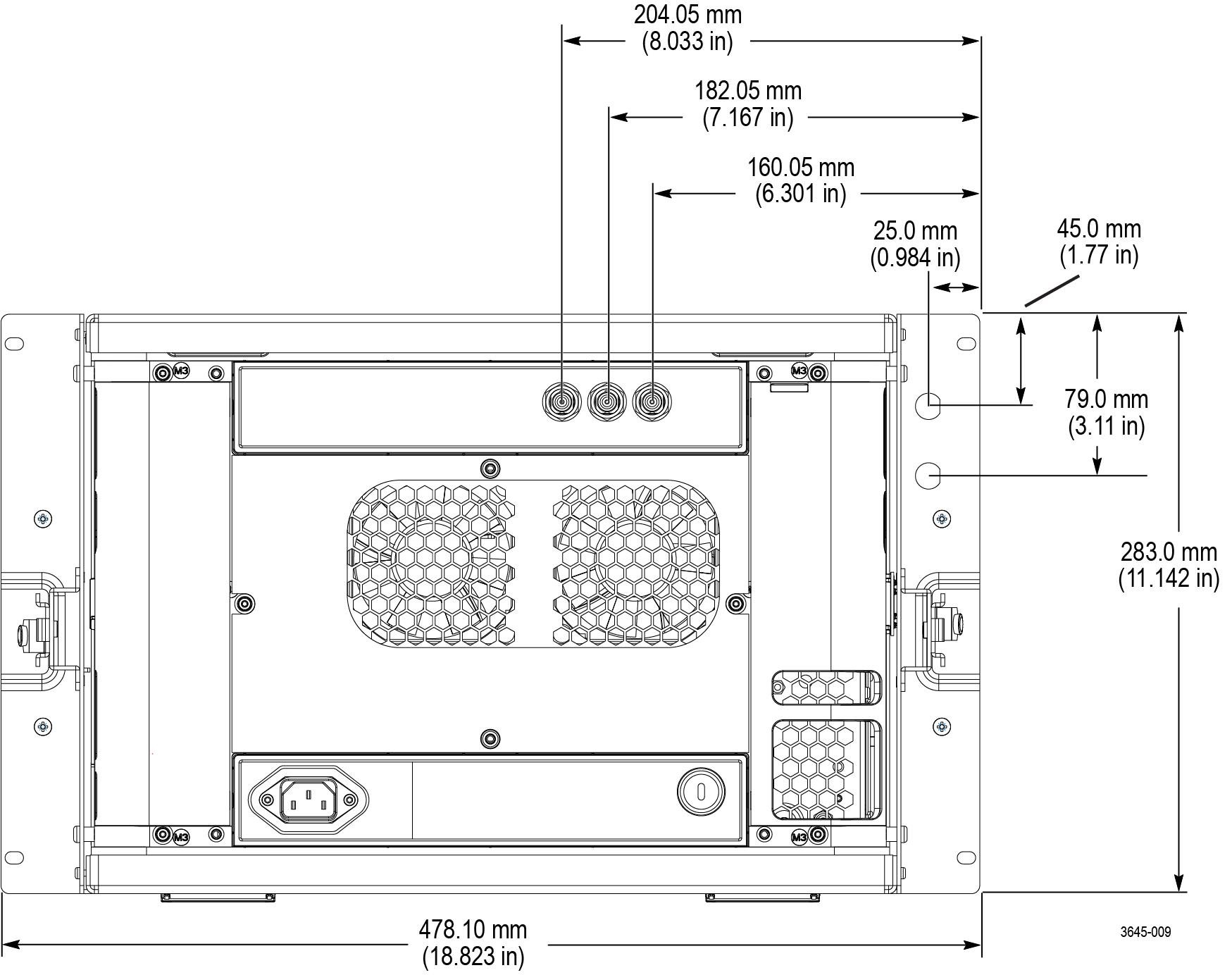
Rear panel dimensions
Help us improve our technical documentation. Provide feedback on our TekTalk documentation forum.