與我們聯絡
與 Tek 業務代表即時對談。 上班時間:上午 6:00 - 下午 4:30 (太平洋時間)
請致電
與 Tek 業務代表即時對談。 上班時間:上午 8:30 - 下午 5:30 (太平洋時間)
下載
下載手冊、產品規格表、軟體等等:
意見回饋
4 Series MSO Standard Instrument Declassification and Security Instructions
This document helps customers with data security concerns to clear or sanitize standard 4 Series MSO instruments (MSO44, MSO46, MSO44B, MSO46B).
此手冊適用於:
MSO44, MSO46, MSO44B, MSO46B
By downloading, you agree to the terms and conditions of the Manuals Download Agreement.
Manuals Download Agreement
ATTENTION: please read the following terms and conditions carefully before downloading any documents from this website. By downloading manuals from Tektronix' website, you agree to the following terms and conditions:
Manuals for Products That Are Currently Supported:
Tektronix hereby grants permission and license to owners of Tektronix instruments to download and reproduce the manuals on this website for their own internal or personal use. Manuals for currently supported products may not be reproduced for distribution to others unless specifically authorized in writing by Tektronix, Inc.
A Tektronix manual may have been revised to reflect changes made to the product during its manufacturing life. Thus, different versions of a manual may exist for any given product. Care should be taken to ensure that one obtains the proper manual version for a specific product serial number.
Manuals for Products That Are No Longer Supported:
Tektronix cannot provide manuals for measurement products that are no longer eligible for long term support. Tektronix hereby grants permission and license for others to reproduce and distribute copies of any Tektronix measurement product manual, including user manuals, operator's manuals, service manuals, and the like, that (a) have a Tektronix Part Number and (b) are for a measurement product that is no longer supported by Tektronix.
A Tektronix manual may be revised to reflect changes made to the product during its manufacturing life. Thus, different versions of a manual may exist for any given product. Care should be taken to ensure that one obtains the proper manual version for a specific product serial number.
This permission and license does not apply to any manual or other publication that is still available from Tektronix, or to any manual or other publication for a video production product or a color printer product.
Disclaimer:
Tektronix does not warrant the accuracy or completeness of the information, text, graphics, schematics, parts lists, or other material contained within any measurement product manual or other publication that is not supplied by Tektronix or that is produced or distributed in accordance with the permission and license set forth above.
Tektronix may make changes to the content of this website or to its products at any time without notice.
Limitation of Liability:
TEKTRONIX SHALL NOT BE LIABLE FOR ANY DAMAGES WHATSOEVER (INCLUDING, WITHOUT LIMITATION, ANY CONSEQUENTIAL OR INCIDENTAL DAMAGES, DAMAGES FOR LOSS OF PROFITS, BUSINESS INTERRUPTION, OR FOR INFRINGEMENT OF INTELLECTUAL PROPERTY) ARISING OUT OF THE USE OF ANY MEASUREMENT PRODUCT MANUAL OR OTHER PUBLICATION PRODUCED OR DISTRIBUTED IN ACCORDANCE WITH THE PERMISSION AND LICENSE SET FORTH ABOVE.
Read Online
Clear and sanitize procedures
This document helps customers with data security concerns to clear or sanitize 4 Series MSO instruments.
This series of instruments contain a processor system with non-removable mass storage.
These products have data storage (memory) devices and data export interfaces (USB and Ethernet). These instructions describe how to clear or sanitize the memory devices and disable the data output interfaces. The instructions also describe how to sanitize an instrument that is not functioning.
Reference
- National Industrial Security Program Operating Manual (NISPOM), DoD 5220.22–M, Chapter 8
- Defense Security Service Manual for the Certification and Accreditation of Classified Systems under the NISPOM
Supported products
Tektronix 4 Series Mixed Signal Oscilloscope products are covered by this document.
Terminology
-
Clear. This eradicates data on media/memory before reusing it in a secured area. All reusable memory is cleared to deny access to previously stored information by standard means of access.
- Erase. This is equivalent to clear.
- Media. Storage/data export device. A device that stores or exports data from the instrument, such as a USB flash drive or USB port.
- Sanitize. This removes the data from media/memory so that the data cannot be recovered using any known technology. This is typically used when the device is moved (temporarily or permanently) from a secured area to a nonsecured area.
- Scrub. This is equivalent to sanitize.
- Remove. This is a physical means to clear the data by removing the memory device from the instrument. Instructions are available in the product service manual.
- User-Accessible. The user can directly retrieve the memory device contents.
- User-Modifiable. The memory device can be written to by the user during normal instrument operation, using the instrument user interface or remote control.
- Volatile memory. Memory that loses data when the instrument is powered off.
- Nonvolatile memory. Memory that retains data when the instrument is powered off.
- Power off. Some instruments have a “Standby” mode, in which power is still supplied to the instrument. For clearing data, putting the instrument in Standby mode does not qualify as powering off. For these products, you must either push a rear-panel OFF switch or remove the power source from the instrument.
- Instrument Declassification. A term that refers to procedures that must be undertaken before an instrument can be removed from a secure environment. Declassification procedures include memory sanitization, memory removal, and sometimes both.
- User data. Describes the type of information stored in the device. Refers to waveforms or other measurement information representing signals connected to the instrument by users.
- User settings. Describes the type of information stored in the device. Refers to instrument settings that can be changed by the user.
- Both. Describes the type of information stored in the device. It means that both user data and user settings are stored in the device.
- None. Describes the type of information stored in the device. It means that neither user data or user settings are stored in the device.
- Directly. Describes how data is modified. It means that the user can modify the data.
- Indirectly. Describes how data is modified. It means that the instrument system resources modifies the data and that the user cannot modify the data.
Memory devices
The following tables list the volatile and non-volatile memory devices in the instrument.
MSO44 and MSO46 Volatile memory devices
These are the memory capacities at the time of publishing this document, but are subject to change.
| Type and size | Function | Type of user info stored | Backed-up by battery | Method of modification | Data input method | Location | User acce-ssible | To clear | To sanitize |
|---|---|---|---|---|---|---|---|---|---|
| SDRAM 4 GB (All models) | Host processor memory | User data | No | Indirectly | Written by processor system | Processor board | No | Unplug the instrument for at least 30 seconds | |
| SDRAM MSO44: 4 GB MSO46: 8 GB | Holds active acquisition data | User data | No | Indirectly | Application software operations | Module socket (SODIMM) on the Acquisition board | No | Unplug the instrument for at least 30 seconds | |
| SDRAM 512 MB | Holds video graphics data | User data | No | Indirectly | Application software operations | Acquisition board | No | Unplug the instrument for at least 30 seconds | |
| CMOS RAM 7 bytes | Holds clock and configuration data | None | Yes | Indirectly | Boot operations | Processor board | No | Cannot be cleared | Unplug the instrument for a minimum of 30 seconds |
| FPGA <30 MB | Interface between compute system and acquisition system | None | No | None | Written by processor system | Acquisition board | No | Unplug the instrument for a minimum of 30 seconds | |
MSO44B and MSO46B Volatile memory devices
These are the memory capacities at the time of publishing this document, but are subject to change.
| Type and size | Function | Type of user info stored | Backed-up by battery | Method of modification | Data input method | Location | User acce-ssible | To clear | To sanitize |
|---|---|---|---|---|---|---|---|---|---|
| SDRAM 8 GB (All models) | Host processor memory | User data | No | Indirectly | Written by processor system | Processor board | No | Unplug the instrument for at least 30 seconds | |
| SDRAM MSO44B: 4 GB MSO46B: 8 GB | Holds active acquisition data | User data | No | Indirectly | Application software operations | Module socket (SODIMM) on the Acquisition board | No | Unplug the instrument for at least 30 seconds | |
| SDRAM 2 GB | Holds video graphics data | User data | No | Indirectly | Application software operations | Acquisition board | No | Unplug the instrument for at least 30 seconds | |
| CMOS RAM | Holds clock and configuration data | None | Yes | Indirectly | Boot operations | Processor board | No | Cannot be cleared | |
| SRAM 4 KB | Host processor power sequencer micro-controller RAM | None | No | Indirectly | Application software operation | Internal to the MSP430 micro-controller on the processor board | No | Unplug the instrument for at least 30 seconds | |
| 32 KB SRAM | Front panel micro-controller RAM | None | No | Indirectly | Application software operation | Internal to the TIVA TM4C micro-controller on the front panel LED board | No | Unplug the instrument for at least 30 seconds | |
| FPGA 6.5 MB | Interface between compute system and acquisition system | None | No | None | Written by NOR Flash | Acquisition board | No | Unplug the instrument for a minimum of 30 seconds | |
MSO44 and MSO46 Non-volatile memory devices
These are the memory capacities at the time of publishing this document, but are subject to change.| Type and size | Function | Type of user info stored | Method of modification | Data input method | Location | User acce-ssible | To clear | To sanitize |
|---|---|---|---|---|---|---|---|---|
| Primary e.MMC 32 GB | Stores Host instrument Linux operating system, application software, and instrument settings | None | Indirect | Written by processor system, software operations | Processor board | No | Not applicable, does not contain user data or settings. Clearing or sanitizing would disable instrument functionality. | |
| Secondary e.MMC 32 GB | Stores user data including waveforms, measurement results and instrument settings | Waveforms, measurement results, instrument settings | Direct | Application software operations and file operations | Processor board | Yes | Remove the processor board (How to sanitize a non-functional instrument) and contact Tektronix service for repair. | |
| EEPROM 2 Kbit | Stores factory data,maintenance data | None | Indirect | Factory operations | Acquisition board | Yes | Not applicable, does not contain user data or settings. Clearing or sanitizing would disable instrument functionality. | |
| EEPROM 1 Kb Two to four pieces depending on model | Stores the SODIMM memory configuration data (SPD) | None | None | Factory operations | Module socket (SODIMM) on acquisition board | No | Not applicable, does not contain user data or settings. Clearing or sanitizing would disable instrument functionality. | |
| Flash Memory 32 KB | Stores power management controller firmware | None | Indirect | Application software operations | Internal to the MC9S08 micro-controller on the acquisition board | No | Not applicable, does not contain user data or settings. Clearing or sanitizing would disable instrument functionality. | |
| Flash Memory 64 KB | Stores analog board micro-controller firmware | None | Indirect | Application software operations | Internal to the KL14 micro-controller on the Acquisition board | No | Not applicable, does not contain user data or settings. Clearing or sanitizing would disable instrument functionality. | |
MSO44B and MSO46B Non-volatile memory devices
These are the memory capacities at the time of publishing this document, but are subject to change.| Type and size | Function | Type of user info stored | Method of modification | Data input method | Location | User acce-ssible | To clear | To sanitize |
|---|---|---|---|---|---|---|---|---|
| e.MMC 64 GB | Stores host instrument Linux operating system, application software, and user data; including waveforms and measurement results, and instrument settings | Stores user data and user settings | Directly | User interface (UI), application software operations, factory operations and programmatic commands | Processor board | Yes | Remove the processor board (How to sanitize a non-functional instrument) and contact Tektronix service for repair. | |
| NOR Flash 32 MB | Stores host processor bootloader | None | Indirectly | Factory operations | Processor board | No | Not applicable, does not contain user data or settings. Clearing or sanitizing would disable instrument functionality. | |
| EEPROM 2 Kbit | Stores factory data, maintenance data | None | Indirectly | Factory operations | Acquisition board | Yes | Not applicable, does not contain user data or settings. Clearing or sanitizing would disable instrument functionality. | |
| EEPROM 1 Kb | Stores power management controller factory data | None | Indirectly | Application software operations | Acquisition board | No | Not applicable, does not contain user data or settings. Clearing or sanitizing would disable instrument functionality. | |
| EEPROM 1 Kb | Stores the host processor memory configuration data (SPD) | None | None | Factory operations | Processor board | No | Not applicable, does not contain user data or settings. Clearing or sanitizing would disable instrument functionality. | |
| EEPROM 1 Kb, two to four pieces depending on model | Stores the SODIMM memory configuration data (SPD) | None | None | Factory operations | Module socket (SODIMM) on acquisition board | No | Not applicable, does not contain user data or settings. Clearing or sanitizing would disable instrument functionality. | |
| Flash Memory 32 KB | Stores power management micro-controller firmware | None | Indirectly | Application software operations | Internal to the MC9S08 micro-controller on the acquisition board | No | Not applicable, does not contain user data or settings. Clearing or sanitizing would disable instrument functionality. | |
| FRAM 32 KB | Stores host processor power sequencer micro-controller firmware | None | Indirectly | Application software operations | Internal to the MSP430 micro-controller on the processor board | No | Not applicable, does not contain user data or settings. Clearing or sanitizing would disable instrument functionality. | |
| Flash Memory 64 KB | Stores analog front end micro-controller firmware | None | Indirectly | Application software operations | Internal to the KL14 micro-controller on the Acquisition board | No | Not applicable, does not contain user data or settings. Clearing or sanitizing would disable instrument functionality. | |
| Flash Memory 256 KB | Stores front panel micro-controller firmware | None | Indirectly | Application software operations | Internal to the TIVA TM4C micro-controller on the front panel LED board | No | Not applicable, does not contain user data or settings. Clearing or sanitizing would disable instrument functionality. | |
| FPGA NOR Flash 64 MB | Stores FPGA configuration | None | Indirectly | Application software operations | Acquisition board | No | Not applicable, does not contain user data or settings. Clearing or sanitizing would disable instrument functionality. | |
| FPGA NOR Flash 64 MB | Stores backup copy of FPGA configuration | None | Indirectly | Application software operations | Acquisition board | No | Not applicable, does not contain user data or settings. Clearing or sanitizing would disable instrument functionality. | |
Media and data export devices
The following table lists the data export devices in the instrument.
| Type | Function | Method of modification | Data input method | Location | User accessible |
|---|---|---|---|---|---|
| USB Host ports | User storage and recall of reference waveforms, screen images, and instrument setups, and installation of firmware updates using removable USB flash drives | Directly | User writeable | Three USB Host ports on front of the instrument; two USB Host ports on the back of the instrument | Yes |
| USB Device port | Remote control and data transfer to a PC | Directly | Remote control using USBTMC | USB Device port on back of the instrument | Yes |
| Ethernet | Transfer data and remote control of instrument. | Directly | Remote control using LXI, VISA, or Socket Server | Ethernet port on back of instrument | Yes |
How to sanitize a working instrument
- Turn the instrument over to another person or department
- Move an instrument (temporarily or permanently) from a secured area to a nonsecured area
- Send an instrument to Tektronix for calibration and/or repair
- Remove any USB memory devices from the instrument, and store or destroy the USB memory devices in accordance with your organization’s guidelines.
- Clear the Network Configuration password (if set):
- Enter the instrument’s IP address into a Web browser on a PC that has network access to the instrument.
- Click the Security for Network Config link on the left side of the screen.
- Click Submit:
- If a password was set for this function, you are requested to enter the password. If the password is accepted, the password is set to blank (the default setting of the access password fields).
- If a password was not set for this function, the screen displays the message that the password was successfully changed (to a blank password).
- Clear the network mDNS Hostname and description:
- Enter the instrument’s IP address into a Web browser on a PC that has network access to the instrument.
- Click the Network Configuration link on the left side of the screen.
- Delete any existing text in both of the Host Settings fields.
- Click the Host Settings Submit button. A message appears stating that the field is empty, and will be configured to the original factory default value.
- Click OK. The message closes and the fields are restored to their original factory settings.
- Clear the Ethernet port settings:
- Disconnect the Ethernet cable from the instrument.
- Open the Utility > I/O menu.
- Clear all information from the Host Name, Domain Name, and Service Name fields.
- Click the Network Address Manual button.
- Manually change the Instrument IP Address, Subnet Mask, Gateway IP Address, and DNS IP Address information to 00.00.00.00.
- Tap Apply Changes. It will take several moments for the changes to take effect.
- Tap outside the menu to close the menu.
 Note:You can also clear the instrument Address settings by accessing the instrument’s web-based interface. Connect the instrument to your network, enter the instrument’s IP address into a Web browser on a PC that is connected to the same network as the instrument, click the Network Configuration link on the left side of the screen, select the Manual TCP/IP Mode box, clear all information from all fields, and click the Submit button for the Address Settings.
- Open the Utility > Security menu and clear the password used to access enabling/disabling ports and software updates. See the Help system for information on the Security menu functions.
- Tap TekSecure Erase Memory to clear/reset internal memory.
- Push the Default Setup button before powering off the instrument.
How to sanitize a non-functional instrument
- Remove all external USB memory devices and store or destroy the USB memory devices in accordance with your organization’s guidelines.
- Follow the instructions in Processor board removal instructions to get access to and remove the Processor board, which contains user data and settings. Store or destroy the Processor board in accordance with your organization’s guidelines.
- Reassemble the instrument without the Processor board and return it to Tektronix. The instrument will then be repaired and calibrated as necessary.
In North America, contact the Tektronix Customer Care Center (1-800-833-9200) for assistance with returning the instrument to a repair center. Worldwide, visit www.tektronix.com to find contacts in your area.
Tektronix does not guarantee calibration after removal and replacement of any module. Adjustment and calibration can be performed only by a Tektronix Service Center. To determine if adjustment and calibration is necessary, perform the Performance Verification procedures found in the Specifications and Performance Verification Manual.
Processor board removal instructions
Use these procedures to remove the Processor board when you need to sanitize a nonfunctional instrument before returning the instrument to Tektronix for repair. Refer to your company's internal policies regarding handling or disposal of the Processor board. A new Processor board is installed and the instrument is repaired and adjusted as necessary.
 | WARNING:Before doing this procedure, disconnect the power cord from the line voltage source. Failure to do so could cause serious injury or death. |
| CAUTION:To avoid damaging other circuits in the instrument, perform the following procedure in a static-safe environment with proper electrostatic discharge controls in place. |
| CAUTION:Do not lay the instrument on its front while disassembling the instrument. All disassembly steps can be done with the instrument positioned as instructed in the steps. Laying the instrument on its front can damage the controls. |
Access the chassis
- Position the instrument in the normal operating position.
- Remove the handle from the instrument:
- Use a Torx T-10 screwdriver to remove two screws from each end of the handle.
- Remove the handle, external handle hubs, and screws aside.
- Remove the metal grill from the rear of the instrument:
- Use a Torx T-10 screwdriver to remove the ten (10) screws located on the grill.
- Remove the grill.
- Remove the internal handle hubs:
- Use a Torx T-10 screwdriver to remove the eight (8) Torx T-10 screws from the internal hub assemblies (four screws on each hub).
- Remove the internal handle hub assemblies and set aside. Keep the hub assemblies together for each side.
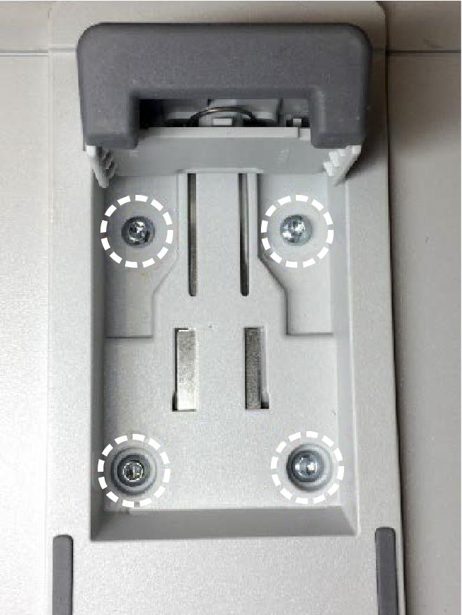
- Remove the feet from the bottom of the instrument:
- Position the instrument so the bottom is facing up.
- Open the feet.
- Use a Torx T-10 screwdriver to remove the four (4) Torx T-10 screwdriver to screws from each foot.
- Remove the feet and set aside.
- Remove the rear plastic case from the instrument:
- Use a Torx T-10 screwdriver to remove the six (6) screws from the back of the instrument case.
- Lift the rear plastic case off the back of the instrument, and set it aside.
- Separate the rear metal chassis from the front chassis (with the instrument still in the bottom-up position):
- Use a Torx T-10 screwdriver to remove the 25 screws securing the rear chassis to the front chassis. There are 24 screws around the chassis edges, and one (1) screw beneath the HDMI connector.
- Remove the three (3) nuts and washers from the BNC connectors.
- Gently pry apart the rear chassis assembly. The rear chassis is held in position mostly by the friction of the three BNC connectors.
- Continue prying the chassis apart until you have the two halves separated and can access the cables.
- Disconnect the two power cable connectors.
The power cables are red on MSO44B and MSO46B insruments.
- Disconnect the smaller cables on the other end of the chassis.
- Set the rear chassis aside.
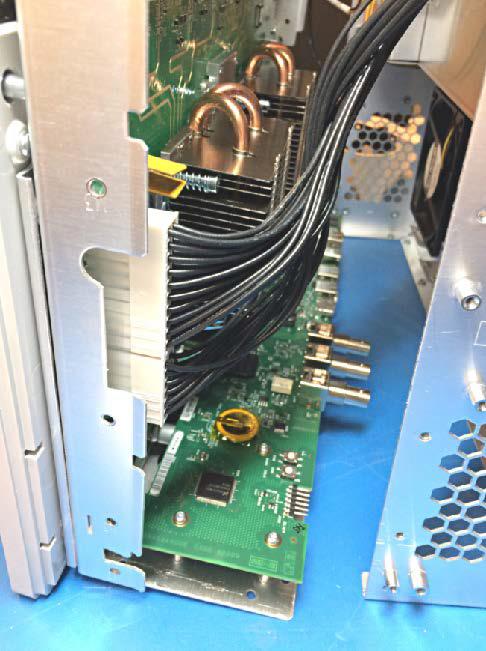
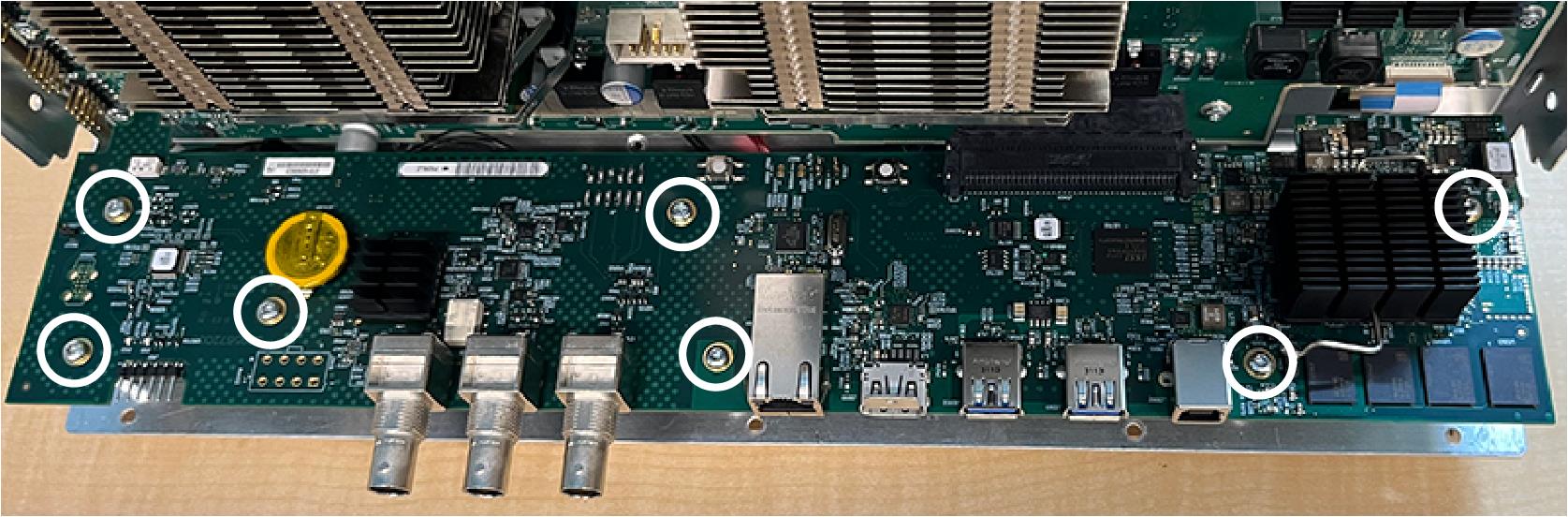
Remove the Processor board
- Use a Torx T-10 screwdriver to remove the seven (7) screws from the Processor board.
- Lift and pull the Processor board away from the chassis. It is still connected with cables, so be careful to not pull it too far.
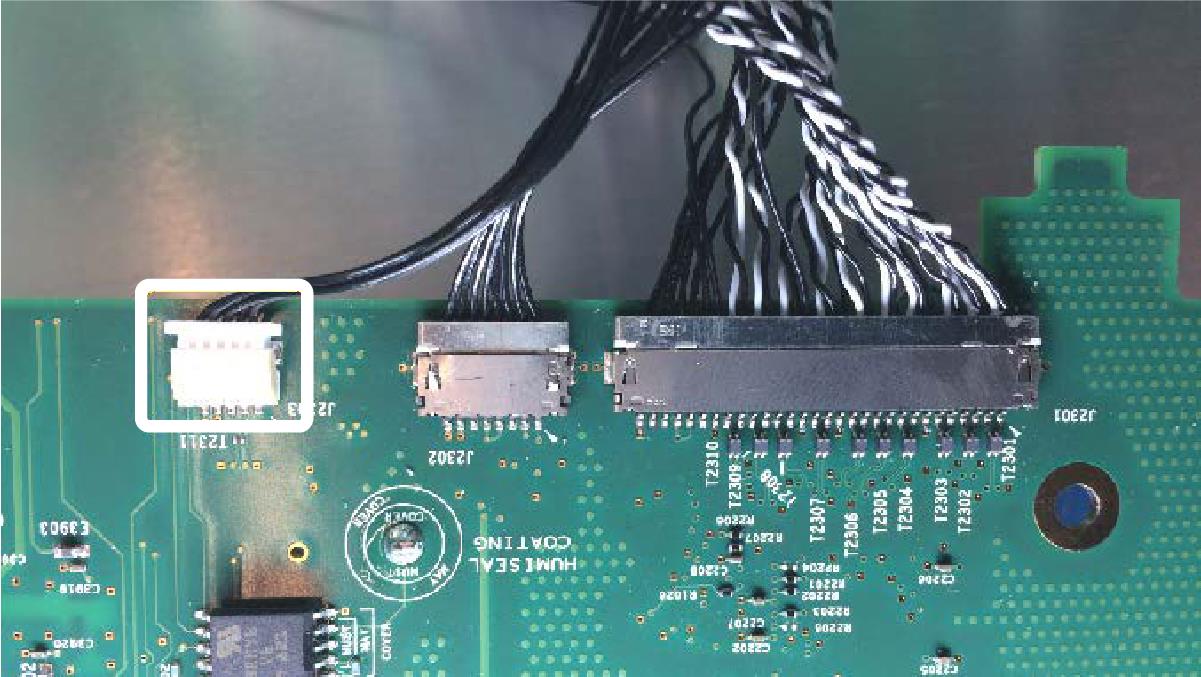
- Carefully rotate the Processor board 180° counterclockwise to get access to the cable connectors.
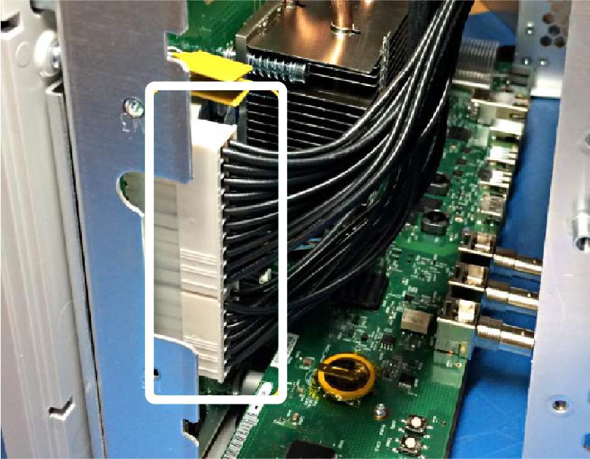
- For MSO44 and MSO46 instruments:
- Disconnect the small white plastic cable connector.
- Position your fingernails so that they are between the edge of the larger-size cable connector and its board connector.
- Gently push and rock the cable connector side to side to move the wire connector out of the board connector.
- Repeat these steps to disconnect the remaining smaller cable connector.
- Disconnect the small white plastic cable connector.
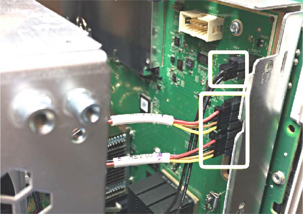
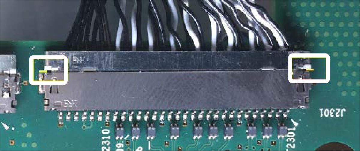
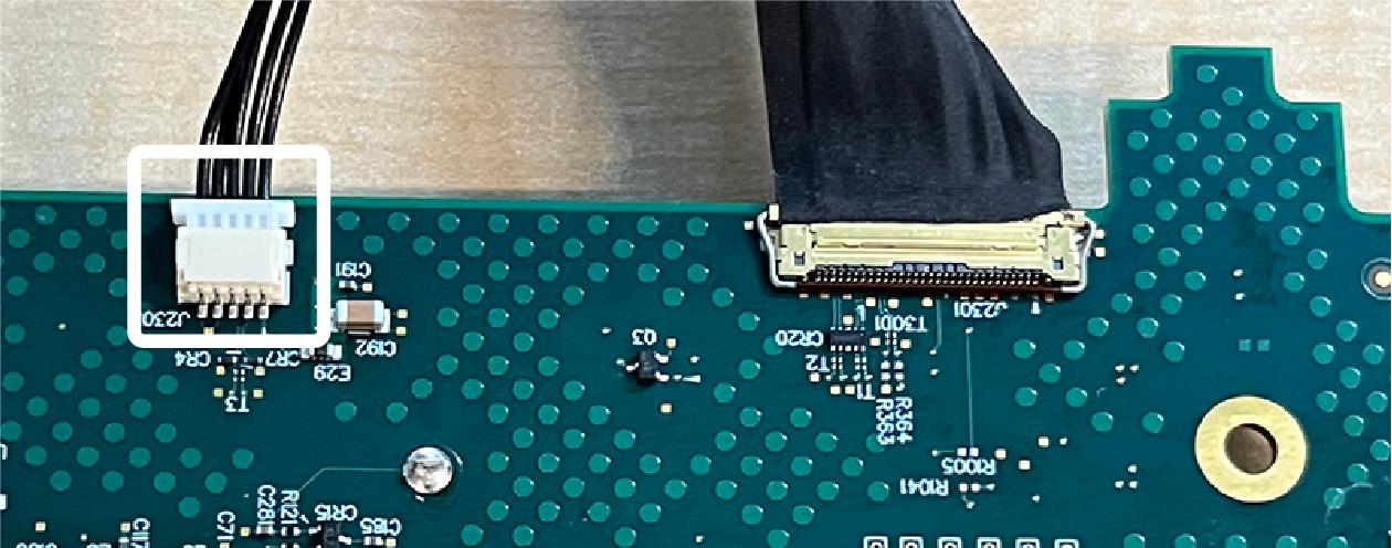
- For MSO44B and MSO46B instruments:
- Disconnect the small white plastic cable connector.
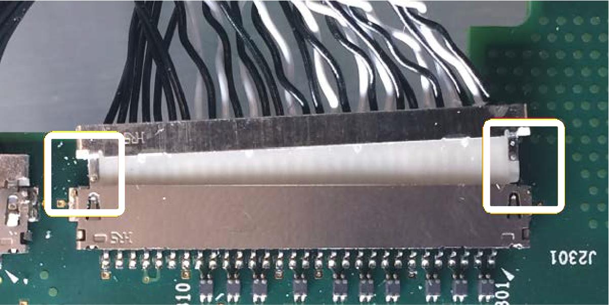
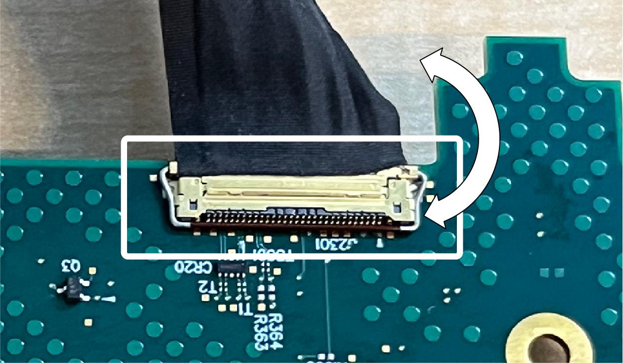
- Lift the baile clip up.
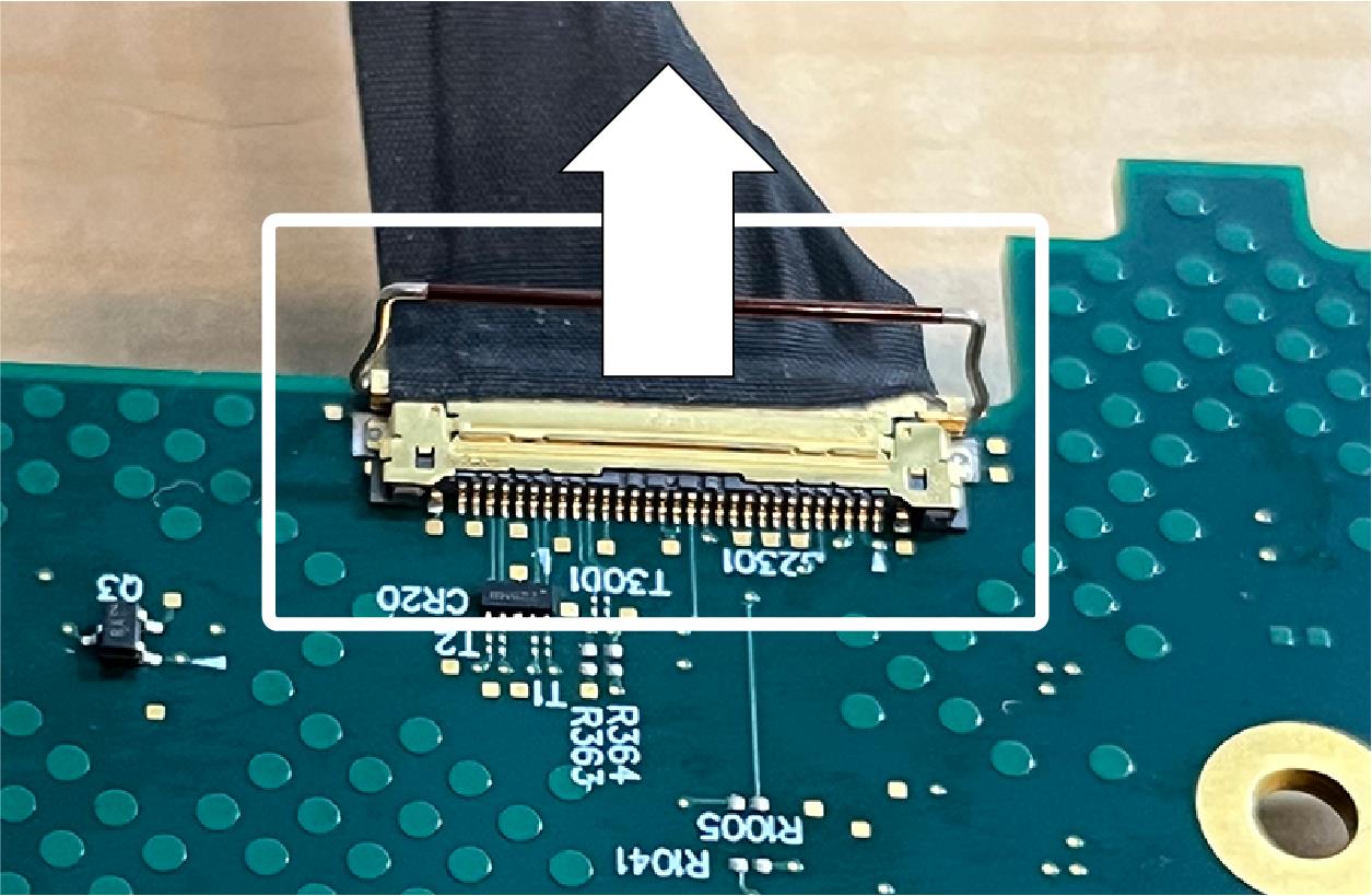
- With the baile clip in the up position, pull the cable connector straight back to disconnect.
- Disconnect the small white plastic cable connector.
- Remove the Processor board. Secure or dispose of the Processor board as directed by your organization’s internal policies regarding handling or disposal of secure devices.
- Reassemble the instrument by using the disassembly steps in reverse order. Tighten the Torx T-10 screws to 0.65 Newton meters.
- Package the reassembled instrument, minus the Processor board, and ship to your nearest Tektronix Service Center for repairs. A new Processor board will be installed
Repair charges
Replacement of damaged and missing hardware is charged according to the rate at the time of replacement.
Help us improve our technical documentation. Provide feedback on our TekTalk documentation forum.