與我們聯絡
與 Tek 業務代表即時對談。 上班時間:上午 6:00 - 下午 4:30 (太平洋時間)
請致電
與 Tek 業務代表即時對談。 上班時間:上午 8:30 - 下午 5:30 (太平洋時間)
下載
下載手冊、產品規格表、軟體等等:
意見回饋
TAP2500, TAP3500, and TAP4000 User Manual
This manual describes the installation and operation of the TAP2500, TAP3500, and TAP4000 active probes.
此手冊適用於:
TAP2500 0, TAP3500 0, TAP4000
By downloading, you agree to the terms and conditions of the Manuals Download Agreement.
Manuals Download Agreement
ATTENTION: please read the following terms and conditions carefully before downloading any documents from this website. By downloading manuals from Tektronix' website, you agree to the following terms and conditions:
Manuals for Products That Are Currently Supported:
Tektronix hereby grants permission and license to owners of Tektronix instruments to download and reproduce the manuals on this website for their own internal or personal use. Manuals for currently supported products may not be reproduced for distribution to others unless specifically authorized in writing by Tektronix, Inc.
A Tektronix manual may have been revised to reflect changes made to the product during its manufacturing life. Thus, different versions of a manual may exist for any given product. Care should be taken to ensure that one obtains the proper manual version for a specific product serial number.
Manuals for Products That Are No Longer Supported:
Tektronix cannot provide manuals for measurement products that are no longer eligible for long term support. Tektronix hereby grants permission and license for others to reproduce and distribute copies of any Tektronix measurement product manual, including user manuals, operator's manuals, service manuals, and the like, that (a) have a Tektronix Part Number and (b) are for a measurement product that is no longer supported by Tektronix.
A Tektronix manual may be revised to reflect changes made to the product during its manufacturing life. Thus, different versions of a manual may exist for any given product. Care should be taken to ensure that one obtains the proper manual version for a specific product serial number.
This permission and license does not apply to any manual or other publication that is still available from Tektronix, or to any manual or other publication for a video production product or a color printer product.
Disclaimer:
Tektronix does not warrant the accuracy or completeness of the information, text, graphics, schematics, parts lists, or other material contained within any measurement product manual or other publication that is not supplied by Tektronix or that is produced or distributed in accordance with the permission and license set forth above.
Tektronix may make changes to the content of this website or to its products at any time without notice.
Limitation of Liability:
TEKTRONIX SHALL NOT BE LIABLE FOR ANY DAMAGES WHATSOEVER (INCLUDING, WITHOUT LIMITATION, ANY CONSEQUENTIAL OR INCIDENTAL DAMAGES, DAMAGES FOR LOSS OF PROFITS, BUSINESS INTERRUPTION, OR FOR INFRINGEMENT OF INTELLECTUAL PROPERTY) ARISING OUT OF THE USE OF ANY MEASUREMENT PRODUCT MANUAL OR OTHER PUBLICATION PRODUCED OR DISTRIBUTED IN ACCORDANCE WITH THE PERMISSION AND LICENSE SET FORTH ABOVE.
Read Online
Important safety information
This manual contains information and warnings that must be followed by the user for safe operation and to keep the product in a safe condition.
To safely perform service on this product, see the Service safety summary that follows the General safety summary.
General safety summary
Use the product only as specified. Review the following safety precautions to avoid injury and prevent damage to this product or any products connected to it. Carefully read all instructions. Retain these instructions for future reference.
This product shall be used in accordance with local and national codes.
For correct and safe operation of the product, it is essential that you follow generally accepted safety procedures in addition to the safety precautions specified in this manual.
The product is designed to be used by trained personnel only.
Only qualified personnel who are aware of the hazards involved should remove the cover for repair, maintenance, or adjustment.
Before use, always check the product with a known source to be sure it is operating correctly.
This product is not intended for detection of hazardous voltages.
Use personal protective equipment to prevent shock and arc blast injury where hazardous live conductors are exposed.
While using this product, you may need to access other parts of a larger system. Read the safety sections of the other component manuals for warnings and cautions related to operating the system.
When incorporating this equipment into a system, the safety of that system is the responsibility of the assembler of the system.
To avoid fire or personal injury
Connect and disconnect properly
Do not connect or disconnect probes or test leads while they are connected to a voltage source.
Use only insulated voltage probes, test leads, and adapters supplied with the product, or indicated by Tektronix to be suitable for the product.
Connect the probe output to the measurement instrument before connecting the probe to the circuit under test. Connect the probe reference lead to the circuit under test before connecting the probe input. Disconnect the probe input and the probe reference lead from the circuit under test before disconnecting the probe from the measurement instrument.
De-energize the circuit under test before connecting or disconnecting the current probe.
Connect the probe reference lead to earth ground only.
Observe all terminal ratings
To avoid fire or shock hazard, observe all rating and markings on the product. Consult the product manual for further ratings information before making connections to the product.
Do not exceed the Measurement Category (CAT) rating and voltage or current rating of the lowest rated individual component of a product, probe, or accessory. Use caution when using 1:1 test leads because the probe tip voltage is directly transmitted to the product.
Do not apply a potential to any terminal, including the common terminal, that exceeds the maximum rating of that terminal.
Do not float the common terminal above the rated voltage for that terminal.
The measuring terminals on this product are not rated for connection to mains or Category II, III, or IV circuits.
Do not connect a current probe to any wire that carries voltages or frequencies above the current probe voltage rating.
Do not operate without covers
Do not operate this product with covers or panels removed, or with the case open. Hazardous voltage exposure is possible.
Avoid exposed circuitry
Do not touch exposed connections and components when power is present.
Do not operate with suspected failures
If you suspect that there is damage to this product, have it inspected by qualified service personnel.
Disable the product if it is damaged. Do not use the product if it is damaged or operates incorrectly. If in doubt about safety of the product, turn it off and disconnect the power cord. Clearly mark the product to prevent its further operation.
Before use, inspect voltage probes, test leads, and accessories for mechanical damage and replace when damaged. Do not use probes or test leads if they are damaged, if there is exposed metal, or if a wear indicator shows.
Examine the exterior of the product before you use it. Look for cracks or missing pieces.
Use only specified replacement parts.
Wear eye protection
Wear eye protection if exposure to high-intensity rays or laser radiation exists.
Do not operate in wet/damp conditions
Be aware that condensation may occur if a unit is moved from a cold to a warm environment.
Do not operate in an explosive atmosphere
Keep product surfaces clean and dry
Remove the input signals before you clean the product.
Provide proper ventilation
Refer to the installation instructions in the manual for details on installing the product so it has proper ventilation.
Slots and openings are provided for ventilation and should never be covered or otherwise obstructed. Do not push objects into any of the openings.
Provide a safe working environment
Always place the product in a location convenient for viewing the display and indicators.
Avoid improper or prolonged use of keyboards, pointers, and button pads. Improper or prolonged keyboard or pointer use may result in serious injury.
Be sure your work area meets applicable ergonomic standards. Consult with an ergonomics professional to avoid stress injuries.
Use only the Tektronix rackmount hardware specified for this product.
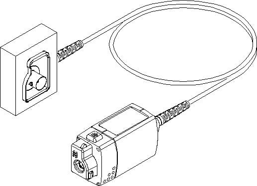
Probes and test leads
Before connecting probes or test leads, connect the power cord from the power connector to a properly grounded power outlet.
Keep fingers behind the protective barrier, protective finger guard, or tactile indicator on the probes. Remove all probes, test leads and accessories that are not in use.
Use only correct Measurement Category (CAT), voltage, temperature, altitude, and amperage rated probes, test leads, and adapters for any measurement.
 | WARNING:To avoid electric shock, keep the probe wire as far from the tip and high voltage circuits as possible. The probe wire voltage rating is less than the probe tip voltage rating. Therefore the probe wire may not provide adequate protection. |
| WARNING:To avoid electric shock, do not use the probe if the wear indicator on the cable becomes visible. Contact Tektronix at tek.com for a replacement. |
Beware of high voltages
Understand the voltage ratings for the probe you are using and do not exceed those ratings. Two ratings are important to know and understand:
- The maximum measurement voltage from the probe tip to the probe reference lead.
- The maximum floating voltage from the probe reference lead to earth ground.
These two voltage ratings depend on the probe and your application. Refer to the Specifications section of the manual for more information.
| WARNING:To prevent electrical shock, do not exceed the maximum measurement or maximum floating voltage for the oscilloscope input BNC connector, probe tip, or probe reference lead. |
Inspect the probe and accessories
Before each use, inspect probe and accessories for damage (cuts, tears, or defects in the probe body, accessories, or cable jacket). Do not use if damaged.
Ground-referenced oscilloscope use
Do not float the reference lead of the probe when using with ground-referenced oscilloscopes. The reference lead must be connected to earth potential (0 V).
Floating measurement use
Do not float the reference lead of the probe above the rated float voltage.
Service the probe and accessories
Go to tek.com/support to find information on contacting Tektronix Service Support.
Terms in this manual and on the product
These terms may appear in this manual:
| WARNING:Warning statements identify conditions or practices that could result in injury or loss of life. |
| CAUTION:Caution statements identify conditions or practices that could result in damage to this product or other property. |
These terms may appear on the product:
- DANGER indicates an injury hazard immediately accessible as you read the marking.
- WARNING indicates an injury hazard not immediately accessible as you read the marking.
- CAUTION indicates a hazard to property including the product.
Symbols on the product
 | When this symbol is marked on the product, be sure to consult the manual to find out the nature of the potential hazards and any actions which have to be taken to avoid them. (This symbol may also be used to refer the user to ratings in the manual.) |
The following symbols(s) may appear on the product.
 CAUTION: Refer to Manual |  Earth Terminal |  WARNING: High Voltage |
Compliance information
This section lists the safety and environmental standards with which the instrument complies. This product is intended for use by professionals and trained personnel only; it is not designed for use in households or by children.
Compliance questions may be directed to the following address:
Tektronix, Inc.
PO Box 500, MS 19-045
Beaverton, OR 97077, US
tek.com
Safety compliance
This section lists the safety standards with which the product complies and other safety compliance information.
Equipment type
Test and measuring equipment.
Safety class
Class 1 – grounded product.
Pollution degree rating
Pollution Degree 2. Normally only dry, nonconductive pollution occurs. Occasionally a temporary conductivity that is caused by condensation must be expected. This location is a typical office/home environment. Temporary condensation occurs only when the product is out of service.
A measure of the contaminants that could occur in the environment around and within a product. Typically the internal environment inside a product is considered to be the same as the external. Products should be used only in the environment for which they are rated.
IP rating
IPX0
Environmental compliance
This section provides information about the environmental impact of the product.
Product end-of-life handling
Observe the following guidelines when recycling an instrument or component:
- Equipment recycling
- Production of this equipment required the extraction and use of natural resources. The equipment may contain substances that could be harmful to the environment or human health if improperly handled at the product’s end of life. To avoid release of such substances into the environment and to reduce the use of natural resources, we encourage you to recycle this product in an appropriate system that will ensure that most of the materials are reused or recycled appropriately.
 |
This symbol indicates that this product complies with the applicable European Union requirements according to Directives 2012/19/EU and 2006/66/EC on waste electrical and electronic equipment (WEEE) and batteries. For information about recycling options, check the Tektronix Web site (http://www.tek.com/productrecycling). |
Installation
This manual describes the installation and operation of the TAP2500, TAP3500, and TAP4000 active probes. Basic probe operations and concepts are presented in this manual. The DPO7000 series oscilloscope and the TAP2500 probe is used in all illustrations in this manual, unless noted otherwise. You can access this document and other related information on tek.com.
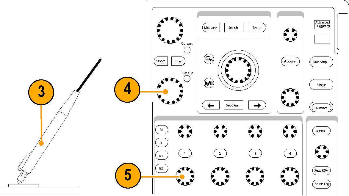
Connecting to the instrument
These instructions describe how to connect your probe to an instrument.
Procedure
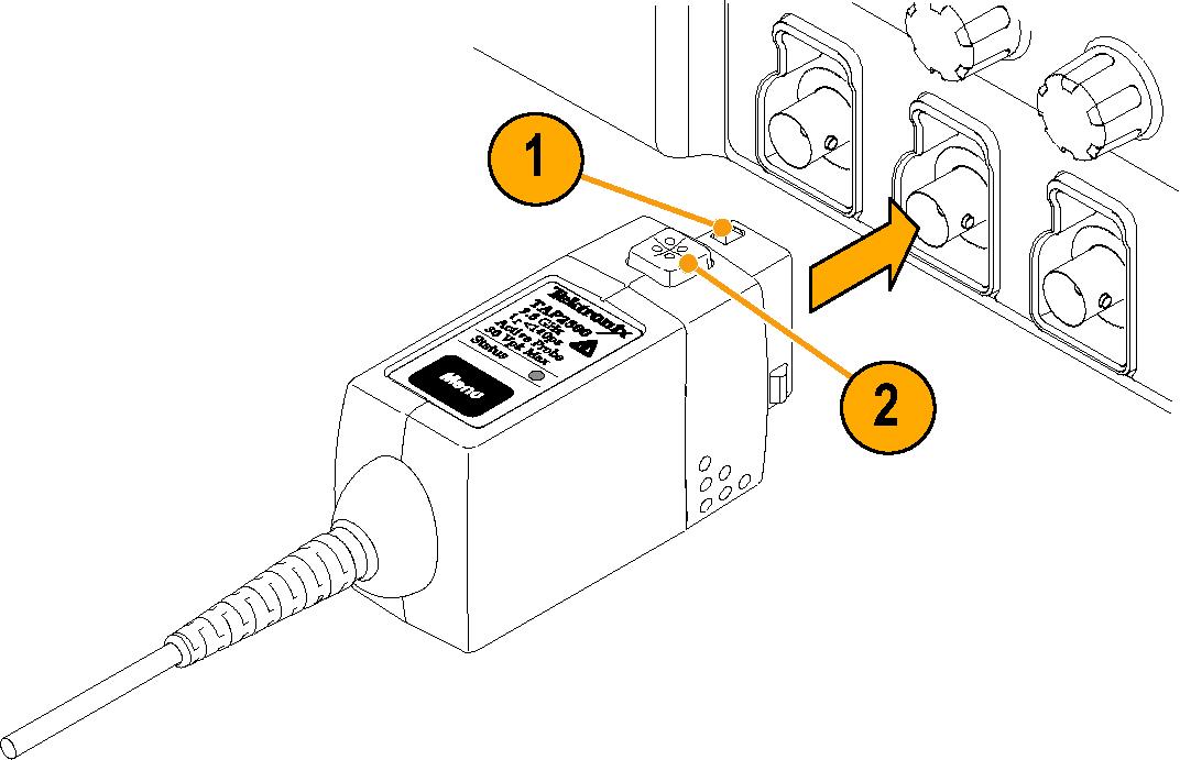
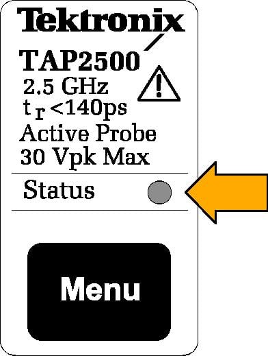
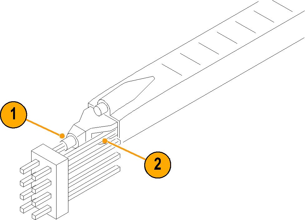
Probe controls and indicators
Status LED
- Glows green after successfully completing the power-on self test routine. The probe is in normal operating mode.
- Glows red if an error condition exists.
The TAP2500, TAP3500, and TAP4000 active probes are designed to work with all TekVPI-interface oscilloscopes and adapters. However, there may be some cases where all of the probe features may not work properly.
If the Status LED glows red during or after probe power on, an internal probe diagnostic fault exists. Disconnect and reconnect the probe to restart the power-on diagnostic sequence. If the Status LED continues to glow red, the probe is defective, and must be returned to Tektronix for repair.
Menu button
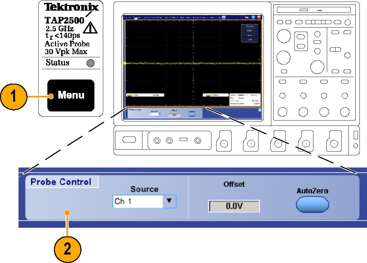
- Press the probe Menu button to display the Probe Control screen on the oscilloscope.
- Use the touch-screen buttons on the instrument to set the probe parameters.
- Press the probe Menu button again to close the Probe Control screen.
AutoZero
- After the 20 minute warm-up period
- When the operating temperature of the probe changes by ±5 °C
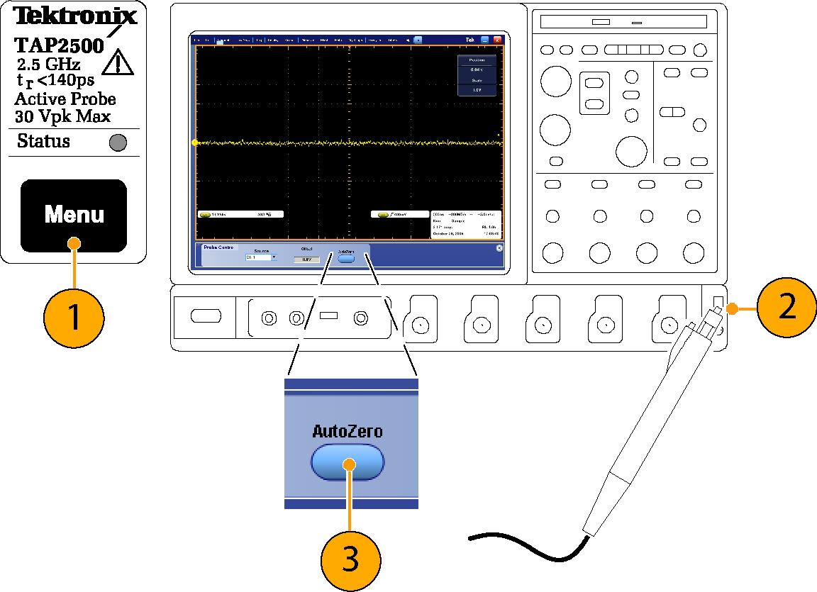
- Press the probe Menu button to display the Probe Control screen on the oscilloscope.
- Short the probe tip to ground.
- Press the AutoZero button on the instrument to execute the AutoZero routine.
Functional check
Use the following procedure to check that your probe is functioning properly. To verify that your probe meets the warranted specifications, refer to the Performance Verification procedures.
Before you begin
Nine-digit part numbers (xxx-xxxx-xx) are Tektronix part numbers.
| Description and quantity | Performance requirement | Recommended example |
|---|---|---|
| Oscilloscope | TekVPI Interface | Tektronix DPO7000 Series, Tektronix 5 Series MSO, Tektronix 6 Series MSO |
| Y-Lead adapter | 0.25-in square pins for probe tip connections | 196-3457-XX (standard accessory) |
| SMT KlipChip adapters (2) | 0.25-in square pins-to-mini clips | 206-0569-XX (standard accessory) |
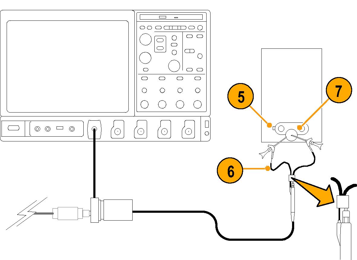
Procedure
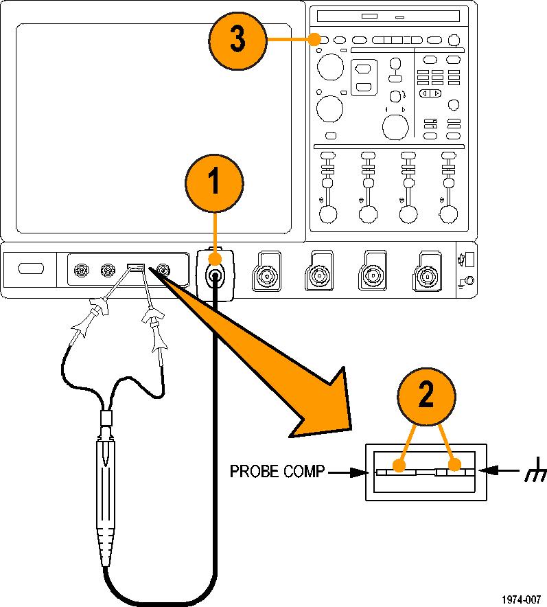
- Connect the probe to any channel of the oscilloscope and set the oscilloscope to display that channel.
- Use the Y-lead Adapter and two SMT KlipChips to connect the probe tip to the PROBE COMP terminals on the oscilloscope.
- Press AUTOSET (or adjust the oscilloscope) to display the calibration waveform. A stable waveform indicates that your probe is functioning correctly.
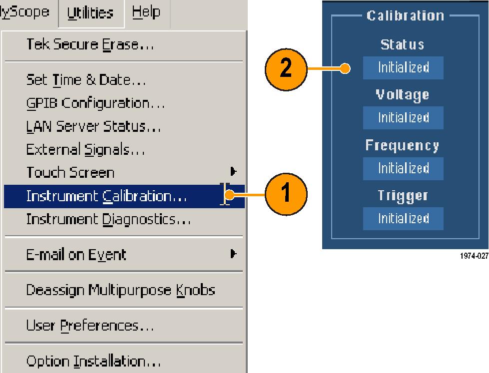
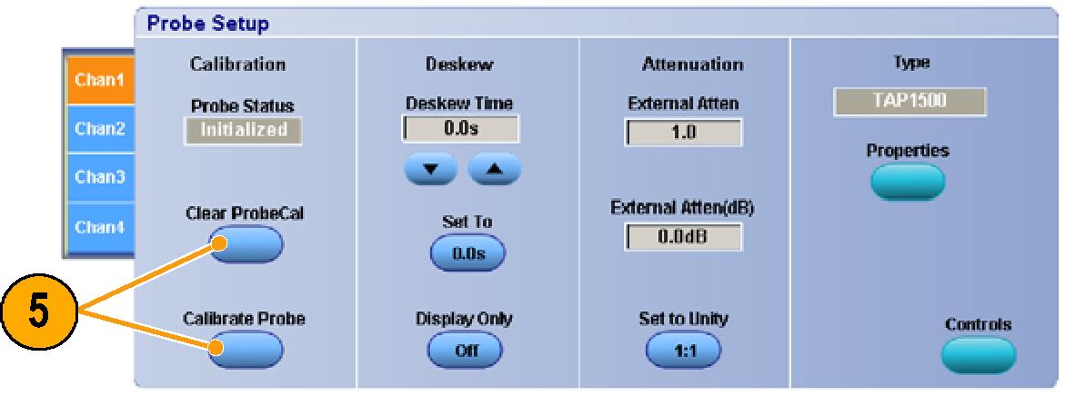
Calibration
The probe calibration routine minimizes your measurement errors by optimizing the gain and offset of the probe and oscilloscope combination. It is recommended that you repeat the probe calibration on each channel that you use. Individual calibration constants are stored for each probe on each channel.
Before you begin
The equipment must be warmed up for 20 minutes, and the calibration status of the host instrument must be pass.
| Description and quantity | Performance requirement | Recommended example |
|---|---|---|
| Oscilloscope | TekVPI Interface | Tektronix DPO7000 Series, Tektronix 5 Series MSO, Tektronix 6 Series MSO |
| Y-Lead adapter | 0.25-in square pins for probe tip connections | 196-3457-XX (standard accessory) |
| SMT KlipChip adapters (2) | 0.25-in square pins-to-mini clips | 206-0569-XX (standard accessory) |
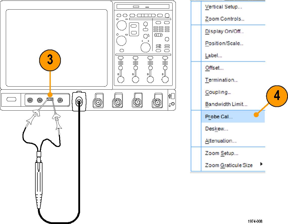
Procedure
Operating information
Use this section to help you use the probe safely and effectively. Read all safety information before installing your measurement system to be aware of the operating and clearance requirements, including possible hazardous areas when the measurement system is connected to the device under test (DUT).
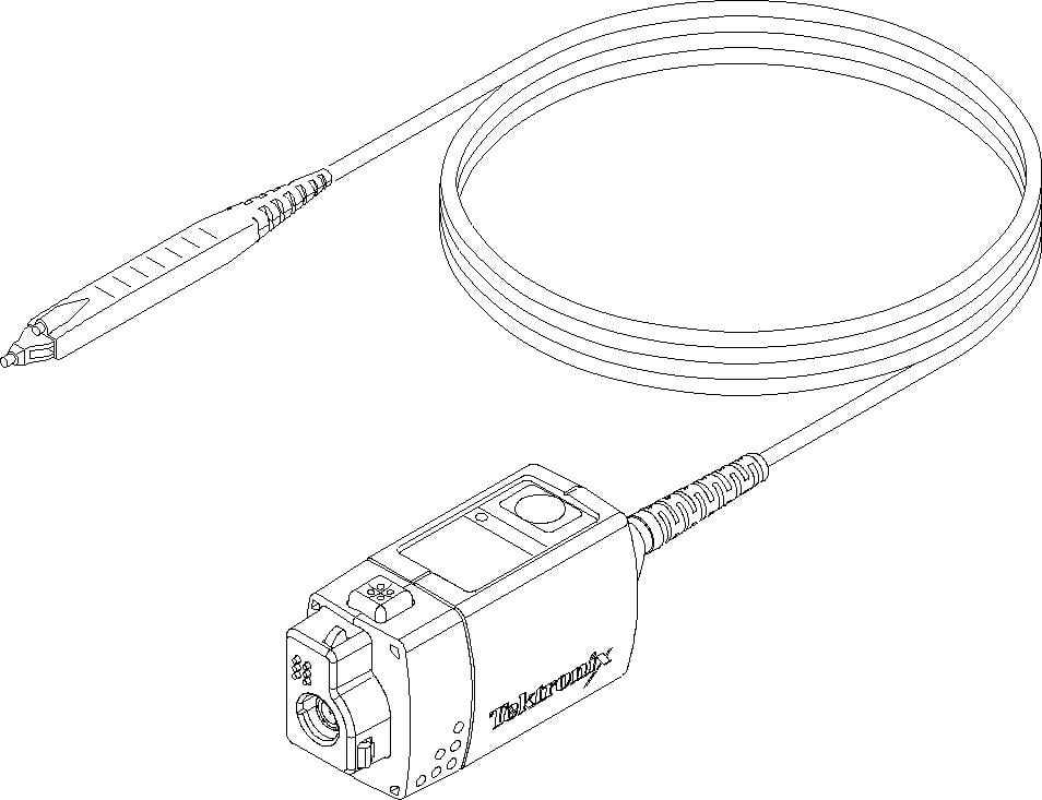
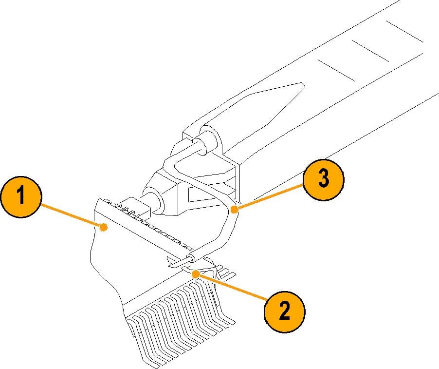
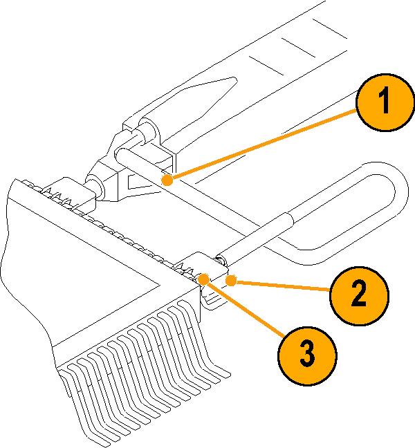
Probe head assembly
The probe head is designed for ease of use and high performance. Its small size makes it easy to handle in tight areas.
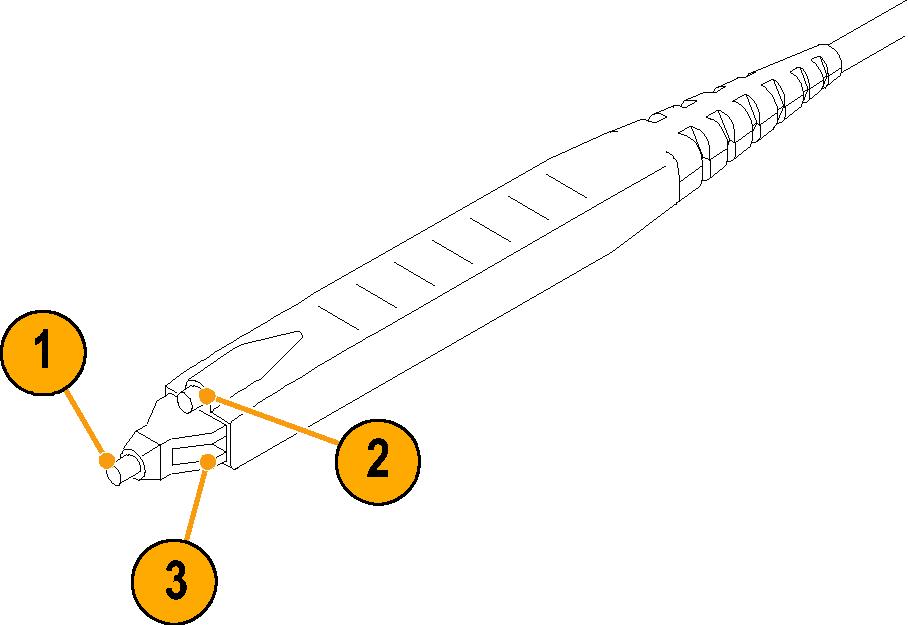
- The probe tip socket is sized to easily press onto 0.025-inch pins for direct access.
- The ground socket provides a short ground path for high-fidelity ground connections.
- The stabilization notch permits you to use adjacent pins to reduce stresses on the probe and pins.
Probe input
The probe is electrically protected against static voltage. However, applying voltages above its design limits may damage the probe tip amplifier.
Input Linear Dynamic Range
The probe head amplifier used by the probe has a limited linear operating range. To keep the input linearity error less than 1% you must limit the signal input voltage to ±4 V (including any DC offset).
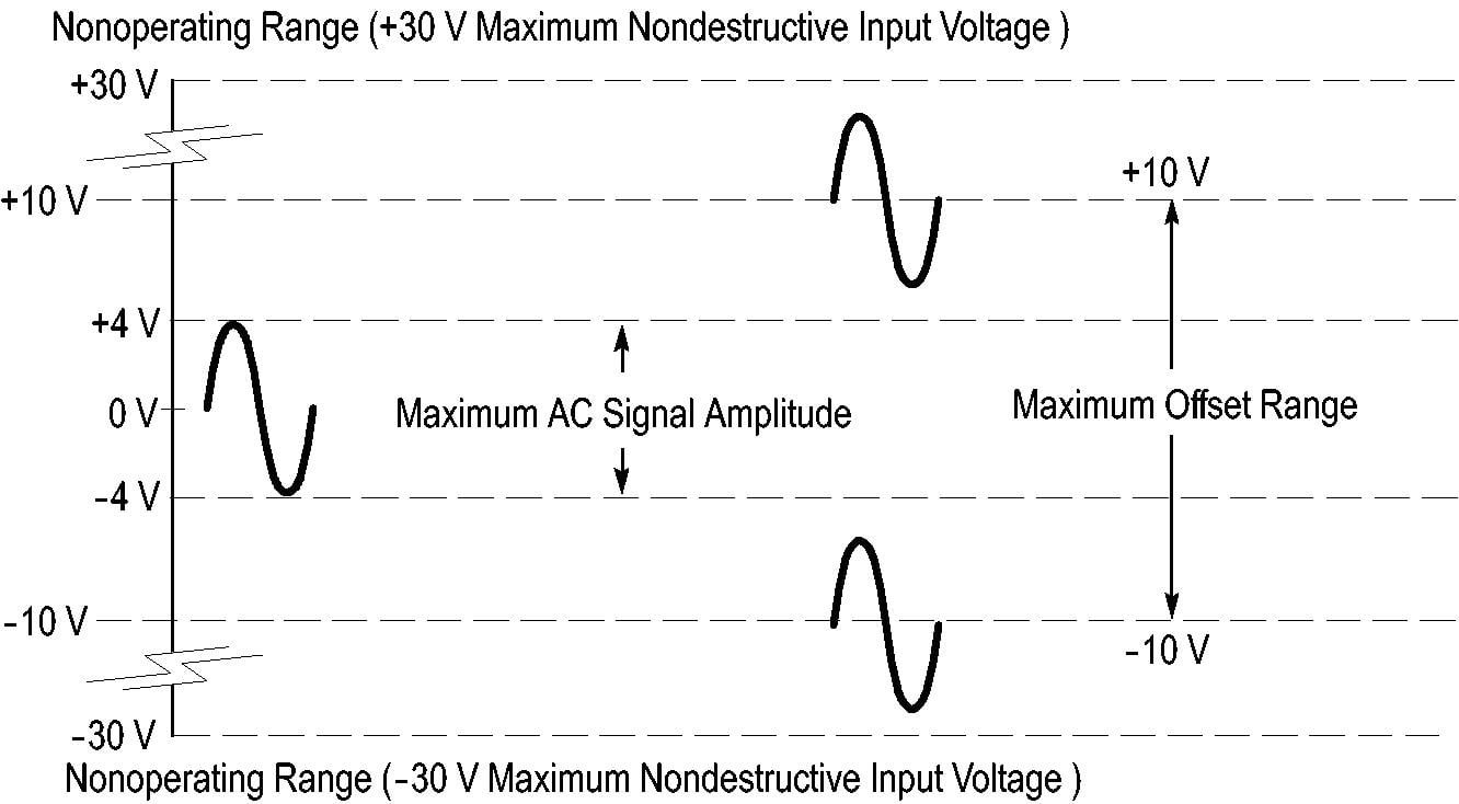
Probe offset
The probe offset is adjustable for operation within the linear range of the probe, and to increase the sensitivity of the probe at higher DC measurement voltages. Using the offset to cancel DC signal components enables optimal probe performance.
Before you begin
See your oscilloscope manual for specific instructions on using the offset control.
The probe has a ±10 V offset range. The linear operating range is ±4 V. If cursors are used on the oscilloscope, the zero reference will be at the probe offset voltage. When you adjust the probe offset with no signal applied to the probe input, the output range is ±4V, (the linear operating range of the probe), not the ±10V offset range of the probe. However, when you apply ±10V to the probe input, the probe offset control can zero this offset.
Procedure
Standard accessories
This section lists the standard accessories and provides information on how to use the accessories.
Specifications are provided where appropriate so that you can choose the accessory that best fits your needs. In some cases, reorder kit quantities differ from the actual number of accessories included with the probe.
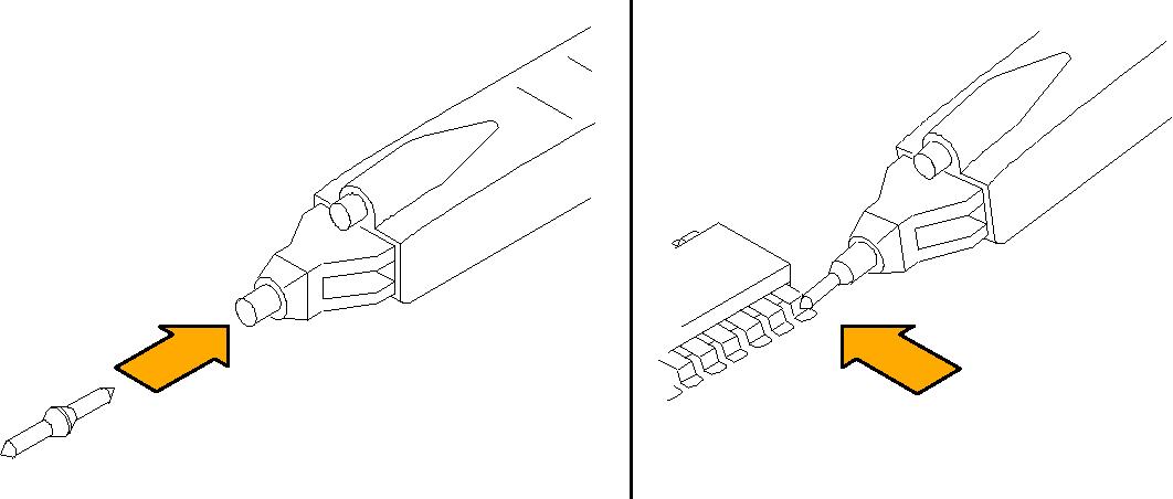
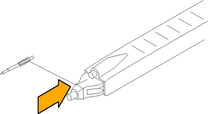
Push-in probe tip
Use the push-in probe tip for general purpose probing by hand. You can also use the push-in probe tip with the other socketed leads and adapters.
Push the tip into the socket until it is seated. Either end of the tip may be used. Do not force the tip. Also, be careful not to injure yourself on the sharp point.
The Tektronix part number is 131-5638-XX (quantity 10).
SureToe adapter
The SureToe adapter is a pointed probe tip useful for probing in dense circuitry. Attach the SureToe adapters the same way as the push-in probe tips.
Do not force the adapter. Also, be careful not to poke yourself with the sharp probe tip. SureToe adapters can be used with any of the socketed accessory leads. Four SureToe adapters are included with the probe.
The Tektronix part number is 131-6254-XX (quantity 4).
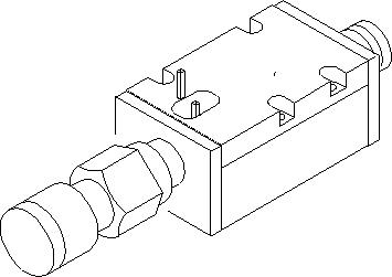
Pogo pin ground
Use the low-inductance ground pogo pin to substantially reduce ground lead inductance and to easily move the probe to different points on the circuit under test.
To attach, press the pogo pin into the probe head ground socket. To maintain signal fidelity while probing, use as short a ground path as possible.
The Tektronix part number is 016-1772-XX (quantity 10).
Square pin socket
The square pin socket is ideal for use with signal/ground pairs on 0.100-inch square header pins. Attach the socket by gently pressing it into the ground socket on the probe head.
Be sure to use the stabilization notch whenever possible to avoid slipping and damaging the probe or circuitry under test.
The Tektronix part number is 016-1773-XX (quantity 10).
Customizable ground lead
You can bend or shorten this ground lead. Cut the tip of the ground lead wire at a 30° to 60° angle to ease insertion into the ground socket of the probe.
To maintain signal fidelity while probing, use as short a ground path as possible.
The Tektronix part number is 196-3482-XX (quantity 5).
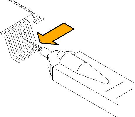
Right-angle adapter
Use the right-angle adapter for low-profile probing of 0.025-inch square pins. The right-angle adapter allows the probe to lie flat against a circuit board, enabling you to probe in tight areas such as between circuit cards.
The right-angle adapter can be used directly with the probe head, or attached to the Y-lead adapter or ground leads.
Attach the right-angle adapter the same way as the push-in probe tip.
The Tektronix part number is 016-1774-XX (quantity 10).
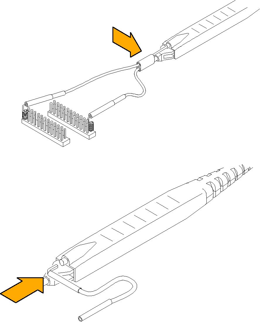
Y-Lead adapter and ground leads
Use the Y-lead adapter to extend the reach of the probe and ground. The Y-lead adapter accepts any of the probe tips or adapters, and can be pushed directly onto 0.025 inch square pins.
Use the ground leads for general, lower-frequency probing. The socketed end of the leads may be connected to any of the probe tips and adapters, or fitted onto 0.025-inch square pins.
When selecting the grounding connection, maintain as short a ground path as possible.
The Tektronix part number is 196-3456-XX. The kit includes: Y-lead adapter (quantity 2), Three-in ground leads (quantity 3).
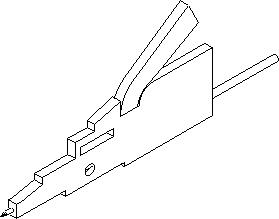
SMT KlipChip adapter
Use the SMT KlipChip test clips to access fragile, dense circuitry. KlipChip test clips can be connected to the Y-lead or ground leads. Simply press the lead socket into the KlipChip handle.
The KlipChip body freely turns, allowing better probe orientation. To reduce stress and provide a lower profile on components being tested, the flexible sleeve of the KlipChip bends up to a 35° angle.
The Tektronix part number is 206-0569-XX (quantity 1).

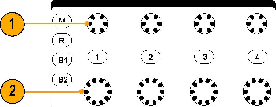
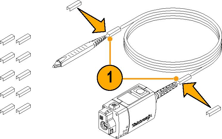
Color band kit (five colored pairs)
- Attach one band to the probe cable and another one of the same color near the probe compensation box.
- Connect the probe to the channel that matches the color of the band.
The Tektronix part number is 016-1315-XX (set of five colors).
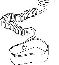
Antistatic wrist strap
When using the probe, always work at an antistatic work station and wear the antistatic wrist strap.
The Tektronix part number is 006-3415-XX.
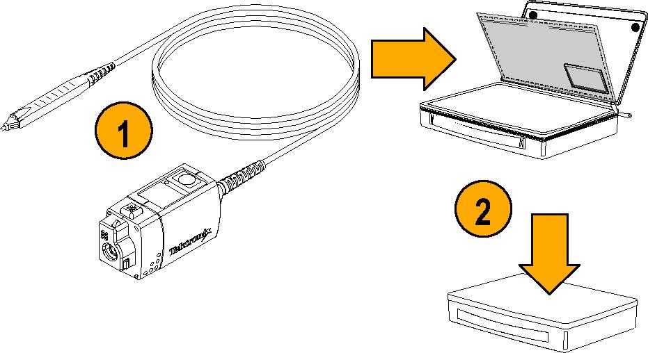
Pouch, nylon carrying case with inserts
- Place the probe and accessories in the carrying case.
- Close the carrying case to transportation or storage.
The Tektronix part number is 016-1952-XX.
Optional accessories
This section lists the optional accessories that you can purchase to help you with your probing tasks.
IC micro-grabber
Use the IC Micro-Grabber to probe the leads on integrated circuits that are surface-mounted.
The Tektronix part number is 013-0309-XX (quantity 2).
SMA-to-probe tip adapter
Use the adapter to connect the probe to SMA cables and for calibration and performance verification. The adapter includes a 50 Ω SMA termination.
The Tektronix part number is 015-0678-XX.
TekVPI calibration fixture
The calibration fixture is required to do a performance verification on the probe. It provides an SMA connector in the probe signal path for internal probe measurements.
The Tektronix part number is 067-1701-XX.
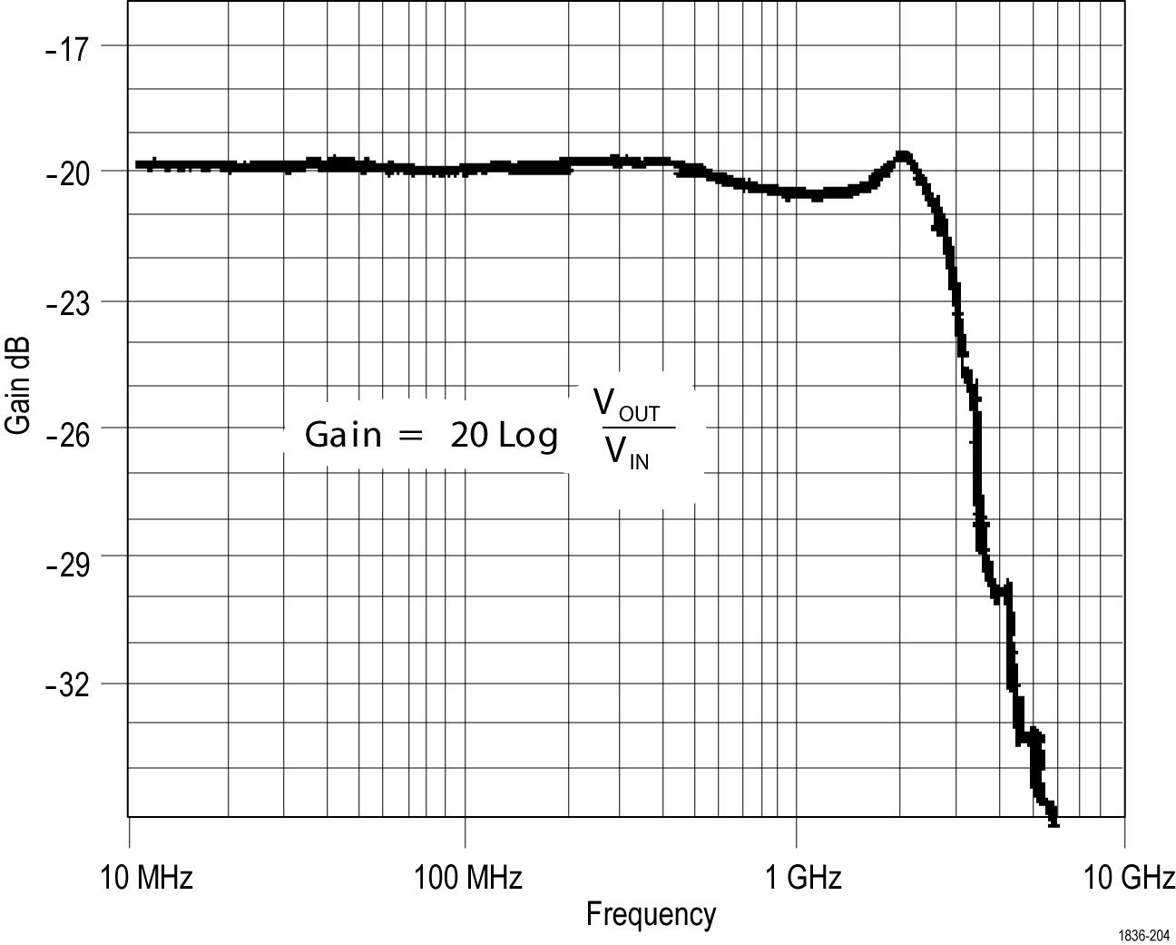
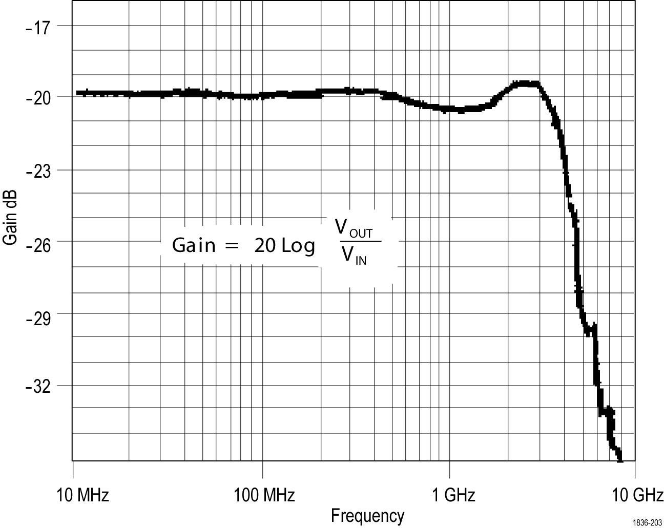
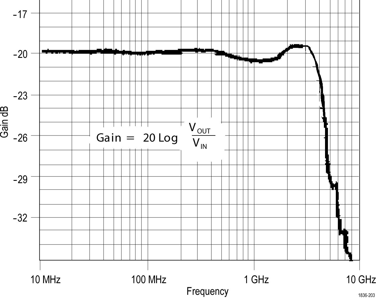
Ground lead length
When you are probing a circuit, you should always use as short a ground lead as possible between the probe head and circuit ground.
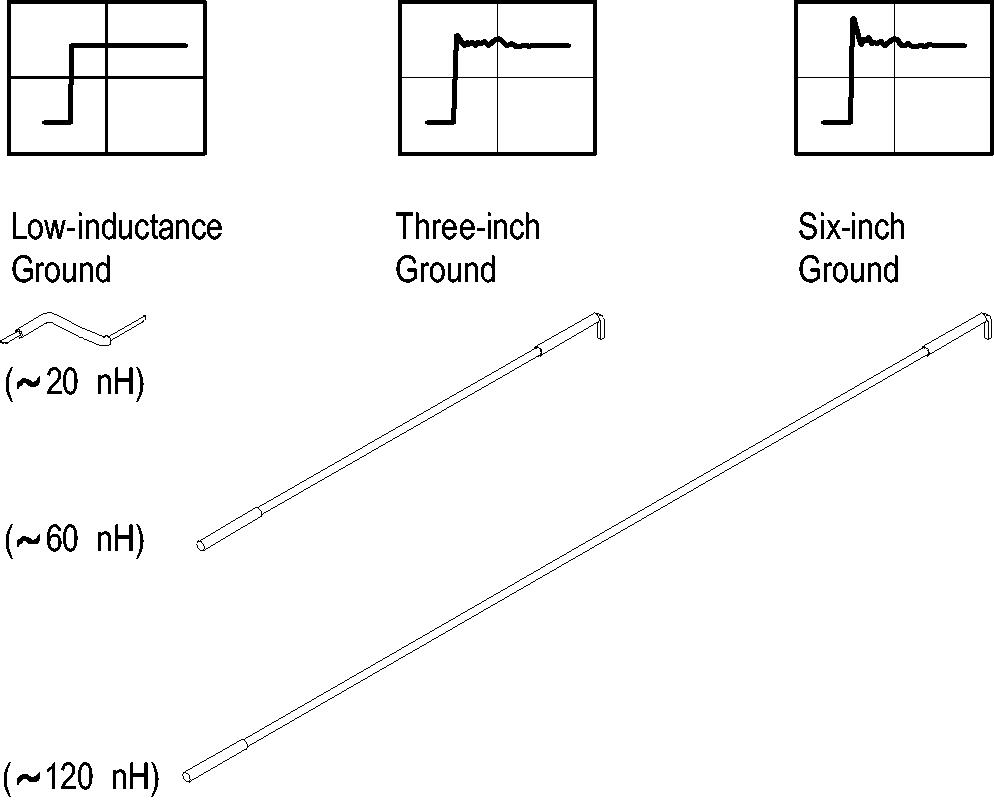
The series inductance added by the probe tip and ground lead can result in a resonant circuit; this circuit may cause parasitic ringing within the bandwidth of your oscilloscope.
Ground lead inductance
When you touch your probe tip to a circuit element, you are introducing a new resistance, capacitance, and inductance into the circuit.
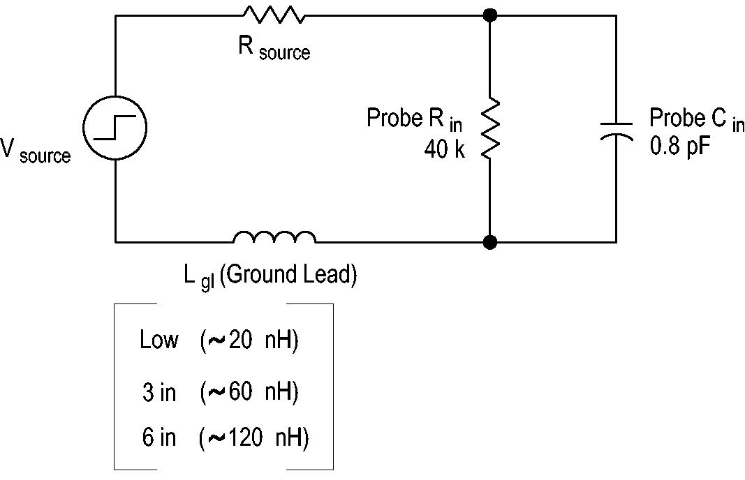
You can determine if ground lead effects may be a problem in your application if you know the self-inductance (L) and capacitance (C) of your probe and ground lead. Calculate the approximate resonant frequency (f0) at which this parasitic circuit will resonate with the following formula:
The equation shows that reducing the ground lead inductance will raise the resonant frequency. If your measurements are affected by ringing, your goal is to lower the inductance of your ground path until the resulting resonant frequency is well above the frequency of your measurements.
The low-inductance ground contacts described in Accessories can help you reduce the effects of ground lead inductance on your measurements.
Low-inductance grounding
Use a ground plane on the package to make probing the package easier, and to avoid adding unnecessary ground lead length and distortion.
About this task
This method is very useful when making many measurements on the same package.
Procedure
- Attach a small piece of copper clad on top of the package.
- Connect the copper clad to the package ground connection.
- Use the low-inductance ground lead to keep the ground lead length as short as possible.
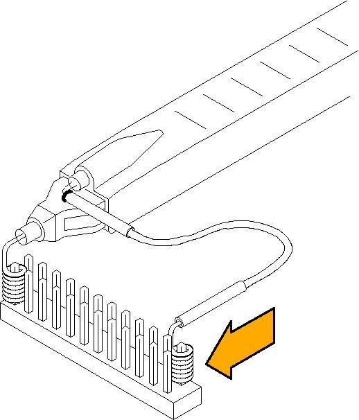
SureFoot Grounding
If you cannot use the low-inductance grounding method recommended, the probe may be grounded to the package under test using a SureFoot™ adapter.
About this task
This method is preferred over using an adjacent circuit ground because it is the shortest ground path possible.
Procedure
- Connect a short ground lead to the probe.
- Attach a SureFoot adapter at the end of the ground lead.
- Connect the SureFoot adapter directly to the package ground.
Probe tip test points
The push-in probe tip or a 0.025-inch square pin can be soldered into a circuit to be used as a temporary test point.
Before you begin
Do not use pieces of solid-core copper wire as test points. If the wire breaks off in the probe tip socket, it may be impossible to remove the wire, and it will prevent insertion of other accessory tips.
The probe tip may be removed and reused by desoldering it from the circuit, and soldering it into another circuit in the future.
Procedure
- Solder the tip onto a lead or pin with a low-power soldering iron.
- Press the probe head onto the tip to take a measurement.
- Pull the probe head off when you are done.
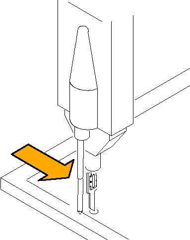
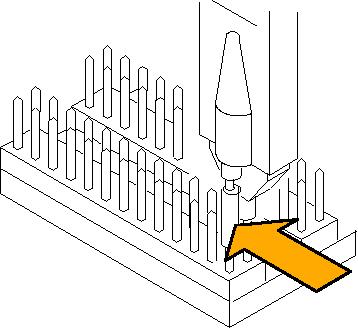
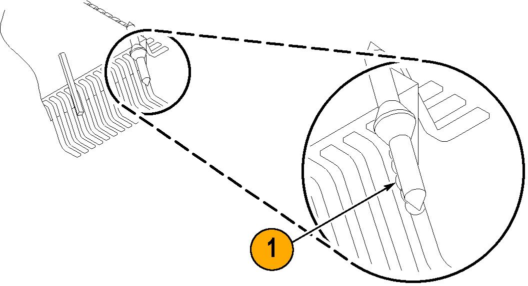
Probe tip stabilization
The probe head has a stabilizing notch for use with 0.100 inch-spaced header pins.
Procedure
Specifications
The specifications are valid under the following conditions.
- The probe has been calibrated at an ambient temperature of 23 °C ±5 °C.
- The probe is connected to a host instrument with an input impedance of 50 Ω .
- The probe and oscilloscope must have a warm-up period of at least 20 minutes and be in an environment that does not exceed the limits described.
- The Signal Path Compensation (SPC) has been run on the oscilloscope before testing the probe specifications.
The Warranted, Typical, and Mechanical characteristics apply to all probe models unless noted otherwise.
Warranted characteristics
Warranted characteristics describe guaranteed performance within tolerance limits or certain type-tested requirements. Warranted characteristics that have checks in the Performance Verification section are marked with the ✔ symbol.
| Characteristic | Description |
|---|---|
| ✔ DC attenuation accuracy (probe only) | 10:1 ±2% (excludes offset error) |
| ✔ Rise time (probe only) | ≤140 ps (TAP2500) |
| ≤130 ps (TAP3500) |
Environmental requirements
| Characteristic | Description |
|---|---|
| Temperature | Operating: 0 to +50 _C (+32 to +122 °F) |
| Nonoperating: -40 to +71 °C (-40 to +160 °F) | |
| Humidity | Operating: 5-95% RH, tested up to +30 °C (+86 °F) 5-85% RH, tested at +30 °C to +50 °C (+86 to +122 °F) |
| Nonoperating: 5-95% RH, tested up to +30 °C (+86 °F) 5-85% RH, tested at +30 °C to +75 °C (+86 to +167 °F) | |
| Altitude | Operating: Up to 3000 meters (9,843 feet) |
| Nonoperating: Up to 12,000 meters (39,370 feet) |
Typical characteristics
Typical characteristics describe typical but not guaranteed performance.
| Characteristic | Description |
|---|---|
| Rise time (probe only) | ≤115 ps (TAP4000) |
| Bandwidth (probe only) | DC to ≥2.5 GHz (TAP2500) |
| DC to ≥3.5 GHz (TAP3500) | |
| DC to ≥4 GHz (TAP4000) | |
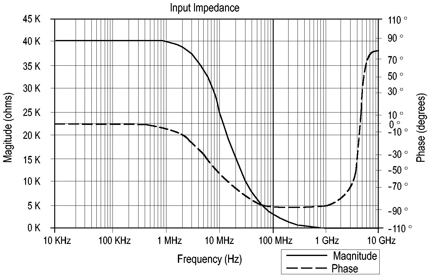
| Input resistance | 40 kΩ |
| Input capacitance | ≤0.8 pF |
| Input signal range | -4.0 V to +4.0 V |
| Input offset range | -10.0 V to +10.0 V |
| Output Zero | ±10 mV or less displayed on screen |
| Maximum non destructive input voltage | ±30 V(DC + peak AC) |
| Linearity | ±0.1% or less over a dynamic range of -3.75 V to +3.75 V ±1.0% or less over a dynamic range of -4.0 V to +4.0 V. |
| DC offset drift | 1.5 mV/ °C or less displayed on screen |
| Signal delay | 5.3 ns ±0.2 ns |
| Characteristic | Description |
|---|---|
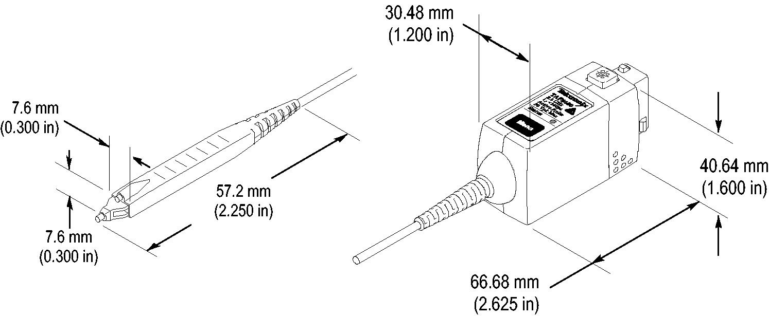
| Dimensions, compensation box | 107 mm × 41 mm × 26 mm (4.2 in × 1.6 in × 1.0 in) |
| Dimensions, probe head | 19.43 mm × 3.30 mm × 7.6 mm (0.765 in × 0.130 in × 0.300 in) |
| Dimensions, cable length | 1.3 m (51 in); from the probe head to the compensation box) |
| Unit weight | 1.55 kg (3.44 lbs); probe, accessories and packaging |
Nominal characteristics
Nominal characteristics describe guaranteed traits, but the traits do not have tolerance limits.
| Characteristic | Description |
|---|---|
| Input coupling | DC |
| Termination | Terminate output into 50 Ω |
| Compatibility | Oscilloscopes equipped with the TekVPI interface |
| Pollution Degree | 2, Indoor use only |
Performance verification
The procedures that follow verify the warranted specifications of the probe.
The recommended calibration interval is one year. Perform the verification procedures in the order listed.
| Description and quantity | Performance requirement | Recommended example |
|---|---|---|
| Oscilloscope | TekVPI Interface | Tektronix DPO7000 Series, Tektronix 6 Series MSO |
| Sampling oscilloscope | ≥12.5 GHz bandwidth | Tektronix TDS8000 Series, Tektronix DSA8300 |
| Sampling module | ≥12.5 GHz bandwidth | Tektronix 80E0X |
| Sampling module | TDR output: 250 mV step, <30 ps rise time | Tektronix 80E04 |
| TekVPI Calibration/Verification adapter | TekVPI Interface | 067-1701-XX |
| DC voltage source | -1.0 to +1.0 VDC, 0.2% accuracy | Wavetek 9100 |
| Digital multimeter (DMM) | Resistance, 0.1% accuracy | Keithley 2700 |
| HF Probe Tip adapter | Probe tip adapter with 50 Ω termination | 015-0678-XX |
| SMA M-to-BNC F adapter | SMA male-to-BNC female | 015-0554-XX |
| BNC-to-dual banana adapter (2) | - | 103-0090-XX |
| BNC cable | 50 Ω , 0.76 m (30 in) length | 012-0117-XX |
| SMA cable (2) | Male-to-Male SMA cable | 012-0649-XX |
| Precision termination | 50 Ω , 0.1%, 0.5 W | 011-0129-XX |
| Y-Lead adapter | 0.25-in square pins for probe tip connections | 196-3457-XX (standard accessory) |
| SMT KlipChip adapters (2) | 0.25-in square pins-to-mini clips | 206-0569-XX (standard accessory) |
| SMA torque wrench | 5/16-in, 7 in-lb. | - |
| SMA adapter wrench | 7/32-in | - |
Nine-digit part numbers (xxx-xxxx-xx) are Tektronix part numbers.
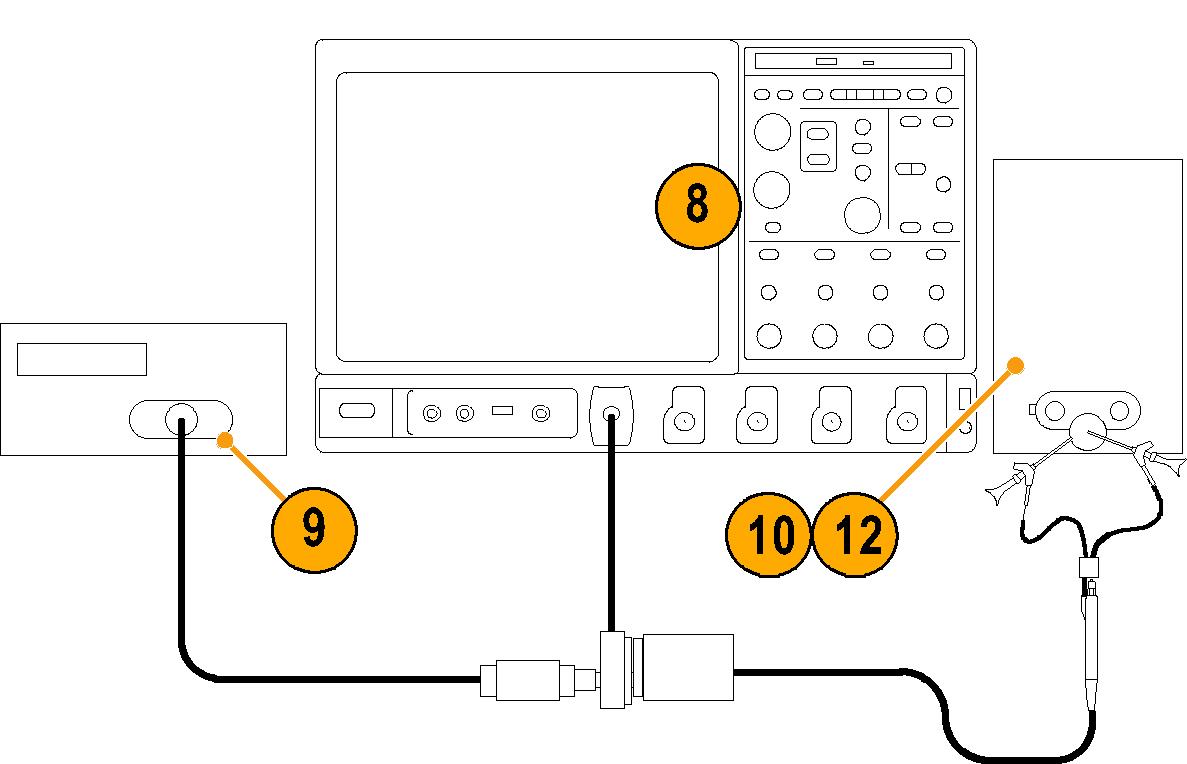
Equipment setup
Use the following procedure to set up and warm up the equipment to test the probe.
Procedure
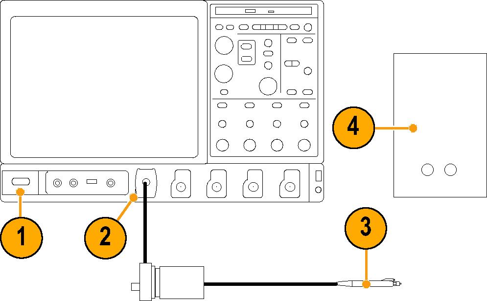
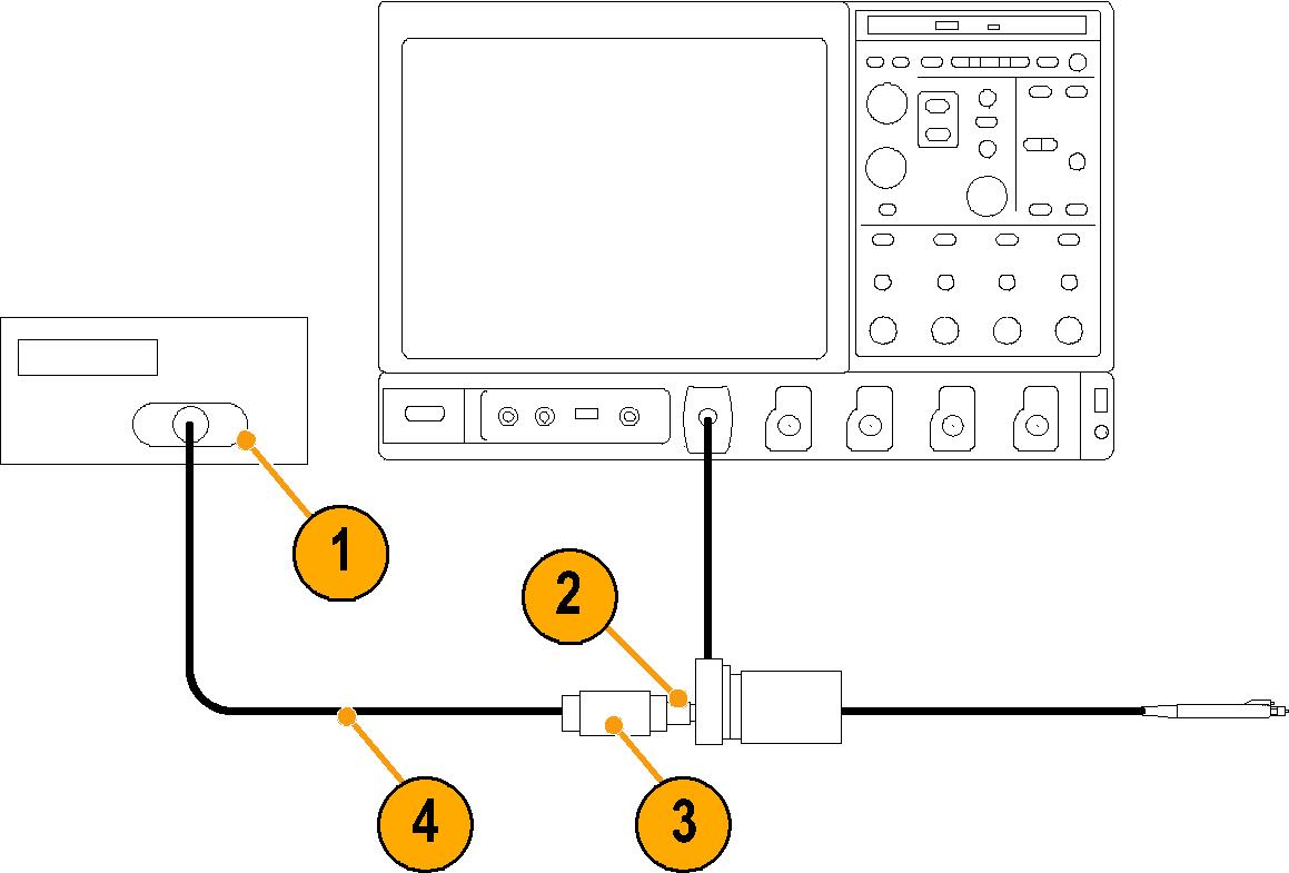
- Turn on the TekVPI oscilloscope.
- Connect the TekVPI Calibration/Verification adapter to the oscilloscope.
- Connect the probe to the TekVPI Calibration/Verification adapter and verify that the Status LED on the probe turns green.
- Turn on the remaining test equipment.
- Allow 20 minutes for the equipment to warm up.
DC gain accuracy
This test checks the DC gain accuracy of the probe.
Procedure
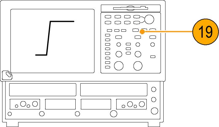
Rise time
This procedure verifies that the probe meets the rise time specification.
Before you begin
| CAUTION:To prevent damage, use care when working with SMA connectors: support equipment to avoid mechanical strain on the connectors, and when tightening connections, use a torque wrench to 7.5 in-lbs. |
About this task
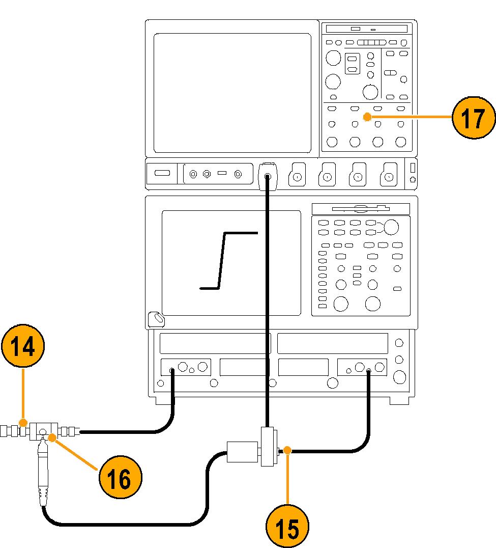
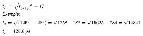
Two rise times are measured; the test system alone, and then the test system with the probe included. The probe rise time is calculated using the two measurements.
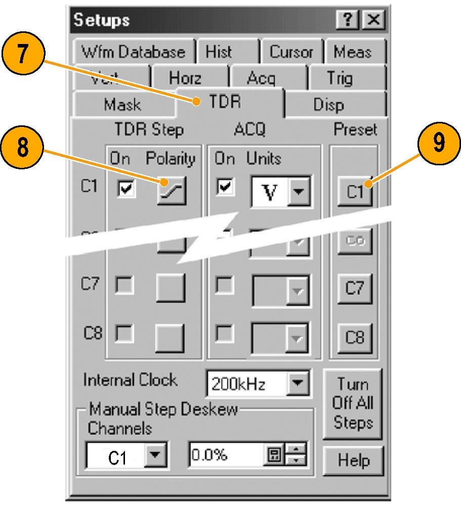
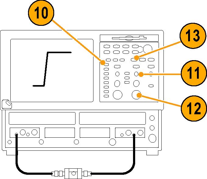
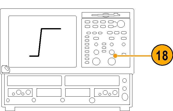
This test uses the TDR function of the 80E04 sampling head as a fast rise time signal source. A second 80E0X sampling head is used to take the measurements. Although the following procedure assigns the TDR and measurement functions to specific oscilloscope channels, any channels can be used. However, the TDR function is only available on 80E04 sampling heads.
Procedure
Test record
Use the test record to record the values of the performance verification checks.
| Probe Model/Serial Number: |
|
| Certificate Number: |
|
| Temperature: |
|
| RH %: |
|
| Date of Calibration: |
|
| Technician: |
|
| Performance test | Source voltage | Minimum | Measured | Calculated | Maximum | |
|---|---|---|---|---|---|---|
| DC Gain Accuracy | +1.00 VDC | +98 mV |
| NA | +102 mV | |
| -1.00 VDC | -102 mV |
| NA | -98 mV | ||
| Rise Time | TAP2500 | NA | NA |
| 140 ps | |
| TAP3500 | NA | NA |
NA | 130 ps | ||
| TAP4000 | NA | NA |
NA | 115 ps | ||
Maintenance
This section contains maintenance information for your probe.
| Note:There are no user replaceable parts within the probe. Refer to Accessories for a list of replaceable accessories for your probe. |
Cleaning
Protect the probe from adverse weather conditions. The probe is not waterproof.
| CAUTION:To prevent damage to the probe, do not expose it to sprays, liquids, or solvents. Avoid getting moisture inside the probe during exterior cleaning. |
Do not use chemical cleaning agents; they may damage the probe. Avoid using chemicals that contain benzine, benzene, toluene, xylene, acetone, or similar solvents.
Clean the exterior surfaces of the probe with a dry, lint-free cloth or a soft-bristle brush. If dirt remains, use a soft cloth or swab dampened with a 75% isopropyl alcohol solution. A swab is useful for cleaning narrow spaces on the probe, use only enough solution to dampen the swab or cloth. Do not use abrasive compounds on any part of the probe.
Returning instrument for service
Use the following instructions for returning your instrument for service.
When repacking the instrument for shipment, use the original packaging. If the packaging is not available or unfit for use, contact your local Tektronix representative to obtain new packaging.
If you need to return your instrument for repair or calibration, call 1-800-438-8165 or complete the form at tek.com/services/repair/rma-request. When you request service, have the serial number, firmware, and software version of the instrument.
If you want to see the warranty or service agreements on your products, or if you want to create your own service price estimate, visit our quick service quote site at tek.com/service-quote.
Help us improve our technical documentation. Provide feedback on our TekTalk documentation forum.