Introduction
The PCI Express® (PCIe®) serial communication standard supports up to 16 lanes of full-duplex data transfer. The standard requires receivers to tolerate some lane-to-lane skew, but exceeding this limit can be detrimental to the link stability and performance. This document describes how to accurately measure the lane-to-lane skew across PCIe transmitters with a maximum data rate of 32 GT/s (Gen5). The procedure can be easily adapted to support the measurement at lower data rates. In part one we show how to deskew the measurement system (real time oscilloscope); part two describes how to configure the device under test (DUT) and perform an accurate lane-to-lane skew measurement.
Part One: Deskew Real Time Oscilloscope Channels
To accurately measure skew from our DUT, we must first deskew the measurement instrument. Typically, four scope channels will be used for lane-to-lane skew measurements. In this guide, we use a Tektronix DPO73304SX which is a four-channel real-time oscilloscope. We deskew all four channels to one target channel. The following steps describe deskewing channels 2, 3, and 4 to channel 1.
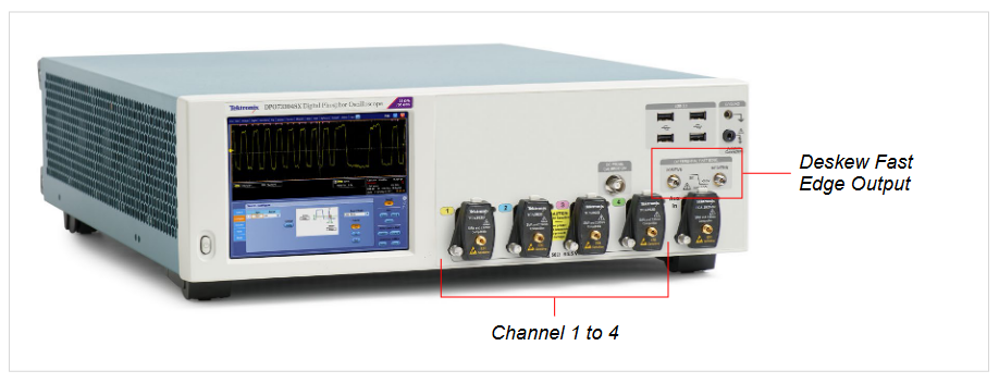
1. Connect the Fast Edge Positive to scope channel 1 and the Fast Edge Negative to scope channel 2 through a pair of phase-matched 2.92 cables.
- NOTE: The phase-matched cable pair suggests within ±1 ps time delay. Tektronix PN: PMCABLE1M
2. Adjust vertical scale to utilize full scale. Note that by specification the output from Fast Edge is 440 mV ± 20 % into a 50 Ohm load.
3. Adjust horizontal settings as following:
- Mode: Manual
- Sample Rate: 100 GS/s
- Record Length: 100K
4. The default trigger settings may be used. Otherwise set as below. Then click the Set to 50% button to automatically set the trigger level.
- Trigger type: Edge
- Source: Ch1
- Slope: Rising
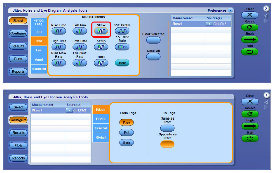
5. Launch DPOJET and configure Skew Measurement
- Go to Analyze -> DPOJET
- In DPOJET: Select -> Time -> Skew Measurement
- Configure Sources -> Ch1, Ch2
- Configure Edges -> From Edge to Rise, To Edge to Opposite From.
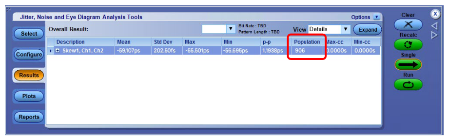
6. Click the Run button on the right. Watch the population count in the DPOJET results. After the population count reaches 1000, click the Stop button.
- NOTE: DPOJET will always show the Red X error indicator when performing this procedure. The error is indicating the measurement does not have enough edges to perform clock recovery. The Skew measurement does not require clock recovery so the error can be safely ignored.
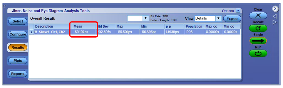
7. Record the Mean value of the Skew measurement.
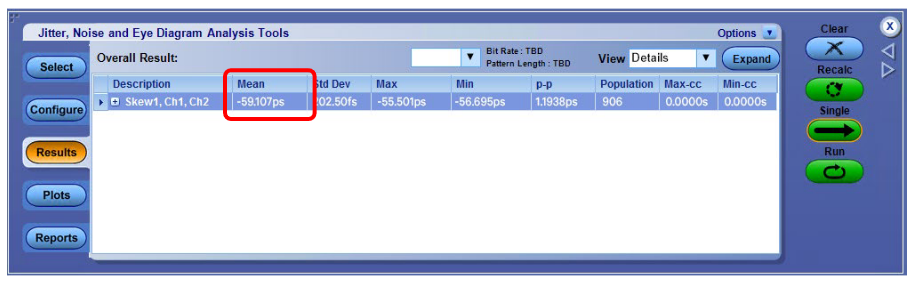
8. Set the skew measurement value to Deskew.
- Go to Vertical -> Deskew
- Select Ch2 from the Channels list.
- Enter the skew measurement value.
9. By now we have completed deskew from Ch2 to Ch1.
10. Move the cable connected to scope Ch2 to Ch3, so now the Fast Edge Negative is connected to Ch3.
11. Go to Vertical -> Vertical Setup and set Ch2 to Display Off and set Ch3 to Display On.
12. Repeat Step 2 to 8 to complete deskew from Ch3 to Ch1.
13. Move the cable connected to scope Ch3 to Ch4, so now the Fast Edge Negative is connected to Ch4.
14. Go to Vertical -> Vertical Setup and set Ch3 to Display Off and set Ch4 to Display On.
15. Repeat Step 2 to 8 to complete deskew from Ch4 to Ch1.
Part Two: Perform Lane-to-Lane Skew Measurement
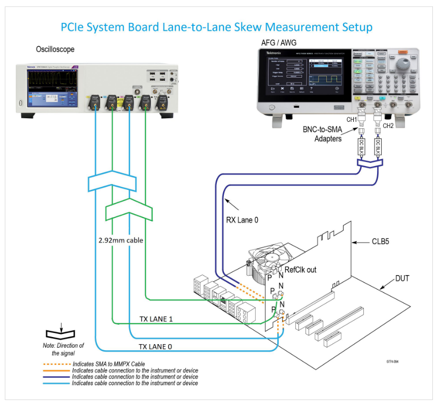
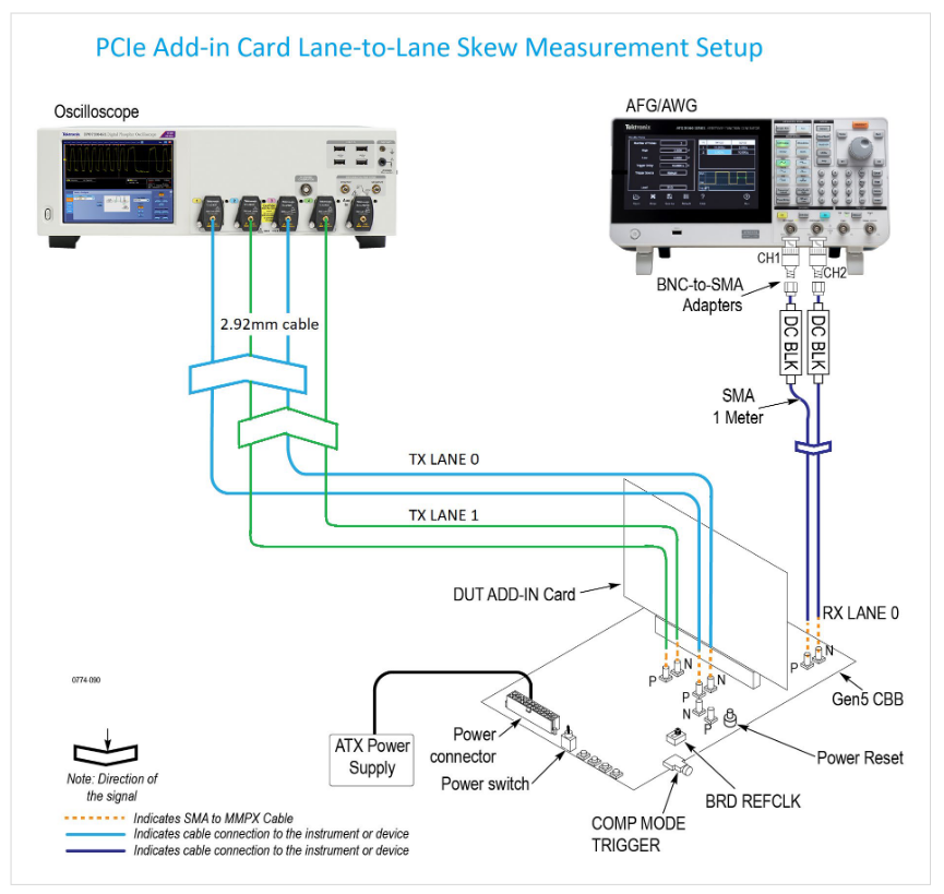
After completing scope channel deskew, it’s time to configure the DUT for lane-to-lane skew measurements. In the following procedure, we first introduce the equipment needed and signal routing for controlling the DUT transmitter output signal. Then we describe the recommended configuration of the DUT and performing a lane-to-lane skew measurement.
1. Prepare the following equipment to use for generating the toggle signal (100 MHz Pulse of 1 ms burst time).
- PCIe Gen 5 CEM Test Fixture (PCI-SIG Rev 3); and,
- Arbitrary Function Generator (Tektronix AFG31252); or,
- Arbitrary Waveform Generator (Tektronix AWG7122C)
2. For transmitters/receivers signal access, set up the following items according to the type of the DUT.
- For BASE DUT – PCIe Gen 5 Evaluation Platform
- For CEM DUT – PCIe Gen 5 CEM Test Fixture
- – System Board – Compliance Load Board (CLB)
- – Add-in Card – Compliance Base Board (CBB)
3. Signal routing
- Connect toggle signal to Rx lane 0.
- – Toggle signal positive -> Rx lane 0 positive; toggle signal negative -> Rx lane 0 negative
- To measure lane 0 to lane 1 skew for example, make the following connection to the scope.
- – Tx lane 0 positive -> scope Ch1
- – Tx lane 0 negative -> scope Ch3
- – Tx lane 1 positive -> scope Ch2
- – Tx lane 1 negative -> scope Ch4
- NOTE: Use the shortest possible cables to minimize insertion loss.
4. The DUT transmitter output signal is controlled by sending a toggle signal (100 MHz Pulse of 1 ms burst time) to the DUT receiver lane 0. The DUT Tx output signal starts with PCIe Gen1 (2.5GT/s) when powered up. By sending the first toggle signal, the DUT Tx output signal will toggle to PCIe Gen2 (5GT/s) with 3.5 dB Preset. Then for the second toggle signal, the DUT output signal will switch to PCIe Gen2 with 6 dB Preset. A third toggle signal will make the DUT transmitting PCIe Gen3 (8GT/s) with Preset 0. We provide a complete list of DUT Tx output signal in Appendix. Note that the DUT output signal will go back to Gen1 once it reaches the last available pattern.
5. To perform lane-to-lane measurement, we recommend configuring DUT transmitter to Preset 6 for PCIe Gen5. This can be done by sending toggle signals 40 times.
- NOTE: As the optimal Tx Preset can vary across different DUT, an optional step is included at the end of this section explaining how to determine optimal Tx Preset using the SigTest analysis tool.
6. Configure scope Horizontal Settings.
- Sampling Mode: IT (Interpolate)
- Mode: Manual
- Sample Rate: 200 GS/s
- Record Length: 625K
7. Configure scope Math Channel for Tx lanes.
- Set Math1 = Ch1 – Ch3
- Set Math2 = Ch2 – Ch4
8. Configure scope trigger setting as follows. The pulse width trigger is used to capture on the 64 ones / 64 zeros portion of the compliance pattern.
- Trigger type: Pulse Width
- Source: Ch1
- Width: 2 ns
9. Launch DPOJET and configure Skew measurement
- Go to Analyze -> DPOJET
- In DPOJET: Select -> Time -> Skew Measurement
- Configure Sources -> Math1, Math2
- Configure Edges -> From Edge to Rise, To Edge Same as From.
10. Click the Single button on the right. Watch the analysis runs and completes. Record the Mean value as the Lane-to-Lane Skew measurement result.
(OPTIONAL) The following steps describe searching for the optimal Preset given the channel presented by the DUT and fixture.
1. Download and install SigTest on the real-time scope. We recommend always using the latest version: SigTest Phoenix 5.1.02 (as of Feb 2022) https://www.intel.com/content/www/us/en/collections/technology/high-speed-io-tools.html?s=Newest
2. Capture and save Math waveforms of each Tx Preset available from the DUT. For example, for PCIe Gen5, capture waveforms of P0, P1, P2, …, P10.
3. Create a table as follows for recording the results.
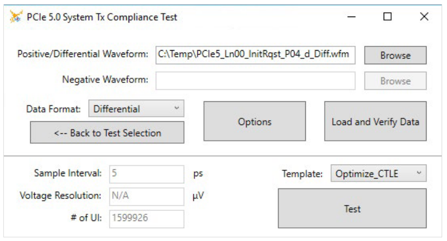
4. Launch SigTest 5.1.2, and run analysis through each Tx Preset waveform with the following recommended configuration.
- Technology: PCIe
- Generation: 5_0
- Test:
- – System Board: System
- – Add-in Card: Card
- Data Format: Differential
- Template: Optimize_CTLE
5. Record the EH @ BER and EW @ BER results in the Overall tab from SigTest Test Results for each Tx Preset.
6. Calculate Eye Area as EH * EW for each Tx Preset.
7. Find the Tx Preset that has the largest Eye Area. Record the Preset number.
NOTE: From empirical data, Preset 5, Preset 6, Preset 8, Preset 9 are typically optimal.
APPENDIX
Compliance Toggle Pattern Table
| Toggle # | Setting #(Base Spec) | Speed | Preset# | Lene-0/8 | Lane-1/9 | Lane-2/10 | Lane-3/11 | Lane-4/12 | Lane-5/13 | Lane-6/14 | Lane-7/15 |
| 1 | 2.5 G | 2.5 G COMPAT | 2.5 G COMPAT | 2.5 G COMPAT | 2.5 G COMPAT | 2.5 G COMPAT | 2.5 G COMPAT | 2.5 G COMPAT | 2.5 G COMPAT | ||
| 1 | 2 | 5 G | 3.5 dB | 5 G COMPAT | 5 G COMPAT | 5 G COMPAT | 5 G COMPAT | 5 G COMPAT | 5 G COMPAT | 5 G COMPAT | 5 G COMPAT |
| 2 | 3 | 5 G | 6.0 dB | 5 G COMPAT | 5 G COMPAT | 5 G COMPAT | 5 G COMPAT | 5 G COMPAT | 5 G COMPAT | 5 G COMPAT | 5 G COMPAT |
| 3 | 4 | 8 G | P0 | 8 G COMPAT | 8 G COMPAT | 8 G COMPAT | 8 G COMPAT | 8 G COMPAT | 8 G COMPAT | 8 G COMPAT | 8 G COMPAT |
| 4 | 5 | 8 G | P1 | 8 G COMPAT | 8 G COMPAT | 8 G COMPAT | 8 G COMPAT | 8 G COMPAT | 8 G COMPAT | 8 G COMPAT | 8 G COMPAT |
| 5 | 6 | 8 G | P2 | 8 G COMPAT | 8 G COMPAT | 8 G COMPAT | 8 G COMPAT | 8 G COMPAT | 8 G COMPAT | 8 G COMPAT | 8 G COMPAT |
| 6 | 7 | 8 G | P3 | 8 G COMPAT | 8 G COMPAT | 8 G COMPAT | 8 G COMPAT | 8 G COMPAT | 8 G COMPAT | 8 G COMPAT | 8 G COMPAT |
| 7 | 8 | 8 G | P4 | 8 G COMPAT | 8 G COMPAT | 8 G COMPAT | 8 G COMPAT | 8 G COMPAT | 8 G COMPAT | 8 G COMPAT | 8 G COMPAT |
| 8 | 9 | 8 G | P5 | 8 G COMPAT | 8 G COMPAT | 8 G COMPAT | 8 G COMPAT | 8 G COMPAT | 8 G COMPAT | 8 G COMPAT | 8 G COMPAT |
| 9 | 10 | 8 G | P6 | 8 G COMPAT | 8 G COMPAT | 8 G COMPAT | 8 G COMPAT | 8 G COMPAT | 8 G COMPAT | 8 G COMPAT | 8 G COMPAT |
| 10 | 11 | 8 G | P7 | 8 G COMPAT | 8 G COMPAT | 8 G COMPAT | 8 G COMPAT | 8 G COMPAT | 8 G COMPAT | 8 G COMPAT | 8 G COMPAT |
| 11 | 12 | 8 G | P8 | 8 G COMPAT | 8 G COMPAT | 8 G COMPAT | 8 G COMPAT | 8 G COMPAT | 8 G COMPAT | 8 G COMPAT | 8 G COMPAT |
| 12 | 13 | 8 G | P9 | 8 G COMPAT | 8 G COMPAT | 8 G COMPAT | 8 G COMPAT | 8 G COMPAT | 8 G COMPAT | 8 G COMPAT | 8 G COMPAT |
| 13 | 14 | 8 G | P10 | 8 G COMPAT | 8 G COMPAT | 8 G COMPAT | 8 G COMPAT | 8 G COMPAT | 8 G COMPAT | 8 G COMPAT | 8 G COMPAT |
| 14 | 15 | 16 G | P0 | 16 G COMPAT | 16 G COMPAT | 16 G COMPAT | 16 G COMPAT | 16 G COMPAT | 16 G COMPAT | 16 G COMPAT | 16 G COMPAT |
| 15 | 16 | 16 G | P1 | 16 G COMPAT | 16 G COMPAT | 16 G COMPAT | 16 G COMPAT | 16 G COMPAT | 16 G COMPAT | 16 G COMPAT | 16 G COMPAT |
| 16 | 17 | 16 G | P2 | 16 G COMPAT | 16 G COMPAT | 16 G COMPAT | 16 G COMPAT | 16 G COMPAT | 16 G COMPAT | 16 G COMPAT | 16 G COMPAT |
| 17 | 18 | 16 G | P3 | 16 G COMPAT | 16 G COMPAT | 16 G COMPAT | 16 G COMPAT | 16 G COMPAT | 16 G COMPAT | 16 G COMPAT | 16 G COMPAT |
| 18 | 19 | 16 G | P4 | 16 G COMPAT | 16 G COMPAT | 16 G COMPAT | 16 G COMPAT | 16 G COMPAT | 16 G COMPAT | 16 G COMPAT | 16 G COMPAT |
| 19 | 20 | 16 G | P5 | 16 G COMPAT | 16 G COMPAT | 16 G COMPAT | 16 G COMPAT | 16 G COMPAT | 16 G COMPAT | 16 G COMPAT | 16 G COMPAT |
| 20 | 21 | 16 G | P6 | 16 G COMPAT | 16 G COMPAT | 16 G COMPAT | 16 G COMPAT | 16 G COMPAT | 16 G COMPAT | 16 G COMPAT | 16 G COMPAT |
| 21 | 22 | 16 G | P7 | 16 G COMPAT | 16 G COMPAT | 16 G COMPAT | 16 G COMPAT | 16 G COMPAT | 16 G COMPAT | 16 G COMPAT | 16 G COMPAT |
| 22 | 23 | 16 G | P8 | 16 G COMPAT | 16 G COMPAT | 16 G COMPAT | 16 G COMPAT | 16 G COMPAT | 16 G COMPAT | 16 G COMPAT | 16 G COMPAT |
| 23 | 24 | 16 G | P9 | 16 G COMPAT | 16 G COMPAT | 16 G COMPAT | 16 G COMPAT | 16 G COMPAT | 16 G COMPAT | 16 G COMPAT | 16 G COMPAT |
| 24 | 25 | 16 G | P10 | 16 G COMPAT | 16 G COMPAT | 16 G COMPAT | 16 G COMPAT | 16 G COMPAT | 16 G COMPAT | 16 G COMPAT | 16 G COMPAT |
| 25 | 26 | 16 G | 16 G CLOCK | 16 G CLOCK | 16 G CLOCK | 16 G CLOCK | 16 G CLOCK | 16 G CLOCK | 16 G CLOCK | 16 G CLOCK | |
| 26 | 27 | 16 G | 16 G CLOCK | 16 G COMPAT | 16 G COMPAT | 16 G COMPAT | 16 G COMPAT | 16 G COMPAT | 16 G COMPAT | 16 G COMPAT | |
| 27 | 28 | 16 G | 16 G COMPAT | 16 G CLOCK | 16 G COMPAT | 16 G COMPAT | 16 G COMPAT | 16 G COMPAT | 16 G COMPAT | 16 G COMPAT | |
| 28 | 29 | 16 G | 16 G COMPAT | 16 G COMPAT | 16 G CLOCK | 16 G COMPAT | 16 G COMPAT | 16 G COMPAT | 16 G COMPAT | 16 G COMPAT | |
| 29 | 30 | 16 G | 16 G COMPAT | 16 G COMPAT | 16 G COMPAT | 16 G CLOCK | 16 G COMPAT | 16 G COMPAT | 16 G COMPAT | 16 G COMPAT | |
| 30 | 31 | 16 G | 16 G COMPAT | 16 G COMPAT | 16 G COMPAT | 16 G COMPAT | 16 G CLOCK | 16 G COMPAT | 16 G COMPAT | 16 G COMPAT | |
| 31 | 32 | 16 G | 16 G COMPAT | 16 G COMPAT | 16 G COMPAT | 16 G COMPAT | 16 G COMPAT | 16 G CLOCK | 16 G COMPAT | 16 G COMPAT | |
| 32 | 33 | 16 G | 16 G COMPAT | 16 G COMPAT | 16 G COMPAT | 16 G COMPAT | 16 G COMPAT | 16 G COMPAT | 16 G CLOCK | 16 G COMPAT | |
| 33 | 34 | 16 G | 16 G COMPAT | 16 G COMPAT | 16 G COMPAT | 16 G COMPAT | 16 G COMPAT | 16 G COMPAT | 16 G COMPAT | 16 G CLOCK | |
| 34 | 35 | 32 G | P0 | 32 G COMPAT | 32 G COMPAT | 32 G COMPAT | 32 G COMPAT | 32 G COMPAT | 32 G COMPAT | 32 G COMPAT | 32 G COMPAT |
| 35 | 36 | 32 G | P1 | 32 G COMPAT | 32 G COMPAT | 32 G COMPAT | 32 G COMPAT | 32 G COMPAT | 32 G COMPAT | 32 G COMPAT | 32 G COMPAT |
| 36 | 37 | 32 G | P2 | 32 G COMPAT | 32 G COMPAT | 32 G COMPAT | 32 G COMPAT | 32 G COMPAT | 32 G COMPAT | 32 G COMPAT | 32 G COMPAT |
| 37 | 38 | 32 G | P3 | 32 G COMPAT | 32 G COMPAT | 32 G COMPAT | 32 G COMPAT | 32 G COMPAT | 32 G COMPAT | 32 G COMPAT | 32 G COMPAT |
| 38 | 39 | 32 G | P4 | 32 G COMPAT | 32 G COMPAT | 32 G COMPAT | 32 G COMPAT | 32 G COMPAT | 32 G COMPAT | 32 G COMPAT | 32 G COMPAT |
| 39 | 40 | 32 G | P5 | 32 G COMPAT | 32 G COMPAT | 32 G COMPAT | 32 G COMPAT | 32 G COMPAT | 32 G COMPAT | 32 G COMPAT | 32 G COMPAT |
| 40 | 41 | 32 G | P6 | 32 G COMPAT | 32 G COMPAT | 32 G COMPAT | 32 G COMPAT | 32 G COMPAT | 32 G COMPAT | 32 G COMPAT | 32 G COMPAT |
| 41 | 42 | 32 G | P7 | 32 G COMPAT | 32 G COMPAT | 32 G COMPAT | 32 G COMPAT | 32 G COMPAT | 32 G COMPAT | 32 G COMPAT | 32 G COMPAT |
| 42 | 43 | 32 G | P8 | 32 G COMPAT | 32 G COMPAT | 32 G COMPAT | 32 G COMPAT | 32 G COMPAT | 32 G COMPAT | 32 G COMPAT | 32 G COMPAT |
| 43 | 44 | 32 G | P9 | 32 G COMPAT | 32 G COMPAT | 32 G COMPAT | 32 G COMPAT | 32 G COMPAT | 32 G COMPAT | 32 G COMPAT | 32 G COMPAT |
| 44 | 45 | 32 G | P10 | 32 G COMPAT | 32 G COMPAT | 32 G COMPAT | 32 G COMPAT | 32 G COMPAT | 32 G COMPAT | 32 G COMPAT | 32 G COMPAT |
| 45 | 46 | 32 G | 32 G CLOCK | 32 G CLOCK | 32 G CLOCK | 32 G CLOCK | 32 G CLOCK | 32 G CLOCK | 32 G CLOCK | 32 G CLOCK | |
| 46 | 47 | 32 G | 32 G CLOCK | 32 G COMPAT | 32 G COMPAT | 32 G COMPAT | 32 G COMPAT | 32 G COMPAT | 32 G COMPAT | 32 G COMPAT | |
| 47 | 48 | 32 G | 32 G COMPAT | 32 G CLOCK | 32 G COMPAT | 32 G COMPAT | 32 G COMPAT | 32 G COMPAT | 32 G COMPAT | 32 G COMPAT | |
| 48 | 49 | 32 G | 32 G COMPAT | 32 G COMPAT | 32 G CLOCK | 32 G COMPAT | 32 G COMPAT | 32 G COMPAT | 32 G COMPAT | 32 G COMPAT | |
| 49 | 50 | 32 G | 32 G COMPAT | 32 G COMPAT | 32 G COMPAT | 32 G CLOCK | 32 G COMPAT | 32 G COMPAT | 32 G COMPAT | 32 G COMPAT | |
| 50 | 51 | 32 G | 32 G COMPAT | 32 G COMPAT | 32 G COMPAT | 32 G COMPAT | 32 G CLOCK | 32 G COMPAT | 32 G COMPAT | 32 G COMPAT | |
| 51 | 52 | 32 G | 32 G COMPAT | 32 G COMPAT | 32 G COMPAT | 32 G COMPAT | 32 G COMPAT | 32 G CLOCK | 32 G COMPAT | 32 G COMPAT | |
| 52 | 53 | 32 G | 32 G COMPAT | 32 G COMPAT | 32 G COMPAT | 32 G COMPAT | 32 G COMPAT | 32 G COMPAT | 32 G CLOCK | 32 G COMPAT | |
| 53 | 54 | 32 G | 32 G COMPAT | 32 G COMPAT | 32 G COMPAT | 32 G COMPAT | 32 G COMPAT | 32 G COMPAT | 32 G COMPAT | 32 G CLOCK |
Resources
1. PCI Express Card Electromechanical Specification R5 V0.9