The Internet of Things (IoT) is a network of physical electronic devices that interoperate in diverse applications from consumer health and fitness to industrial control and automation to reduce human error and increase efficiency. A typical IoT device contains at least one sensor, a processor, and a radio chip that operates in different states and consumes currents from tens of nanoamps to hundreds of milliamps in a matter of tens of microseconds.
Power management is a primary concern in IoT device design. The battery life in these devices can vary from as short as days, such as in consumer wearables, to as long as 20 to 30 years in sensor nodes that are located in remote locations where replacing the battery is difficult. Although these devices are enabled by the introduction of components that operate on very low power levels, the ability to accurately describe the power consumption of each, as well as overall operation on a system level, is essential in reducing energy consumed and optimizing battery life.
This e-guide describes the top 11 power management challenges that you can face when designing, validating, or testing your IoT device and offers some tips on how to simplify the process and ultimately enable the success of your IoT device.
Measuring a Wide Dynamic Range of Current Levels
For all IoT applications, a device must perform a diverse array of operations, including:
- Deep sleep
- Data processing
- Data acquisition
- Data display
- User interaction
- Data transmission to a gateway
Given the number of modes associated with different states of operation, the current consumed will span from hundreds of nanoamps to hundreds of milliamps within the blink of an eye. While conventional instruments may meet either the low end, such as a picoammeter, or the high end, such as a current probe, they typically will not meet both ends of your current spectrum. And reconfiguring instrument settings or even test setups is both error-prone and impractical. Most ammeters and digital multimeters (DMMS) offer the ability to auto-range through a few measurement ranges. However, the limitation to implementing auto-ranging in both hardware and firmware may introduce glitches and latency to your measurement - and produce an inaccurate or even incorrect measurement result.
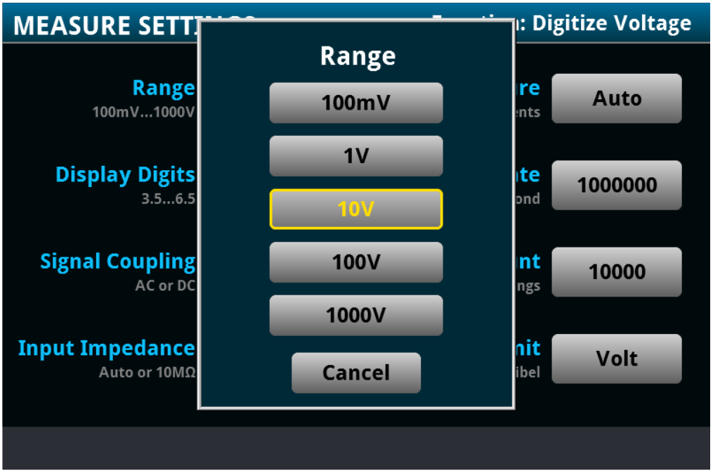
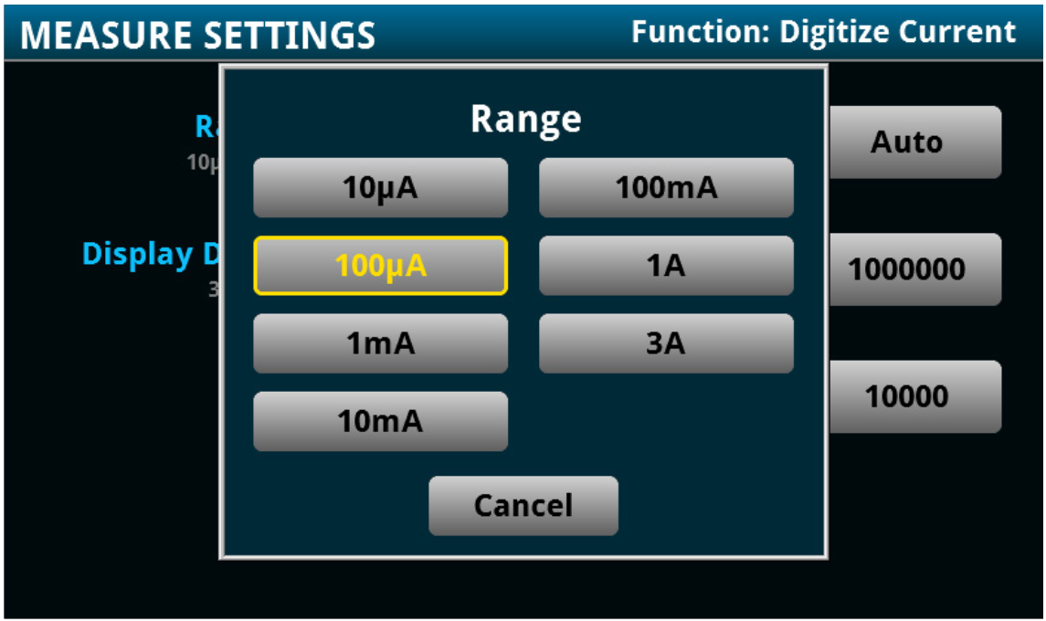
Tip: Use a DMM with a single configuration setup to capture a wide dynamic measurement range of voltage and current.
Determining Ultra-Low Deep Sleep Current
In many IoT applications, the device idles for a long period of time before waking to perform tasks, creating many opportunities in system design to conserve power. New developments in low power management have launched a wide range of ultra-low power sleep modes that provide finer levels of granularity beyond just run or idle modes, as well as more sophisticated strategies for limiting power consumption. These modes, such as standby, doze, sleep, and deep sleep, consume current from tens of microamps to as low as tens of nanoamps.
Accurately measuring current in the hundreds or tens of nanoamps is not a trivial task. Most current measuring techniques, such as current probing, simply cannot achieve the sensitivity at these ultra-low current levels.
When an ammeter is used, low current measurement accuracy can be seriously impacted by a number of error sources:
- Connections between the device and the instrument
- Ammeter input bias current
- Burden voltage from the internal series resistance that can be as high as 500mV
- Source resistance of the device under test
- Leakage current from cables and fixtures
- Currents generated by triboelectric or piezoelectric effects
In a shunt ammeter, selecting a smaller resistor value reduces the input time constant and results in faster instrument response time. However, it will degrade the signal-to-noise ratio in an effort to minimize circuit loading and voltage burden. When measuring low current levels, the small signal degrades the signal-to-noise ratio and significantly impacts the accuracy and sensitivity of the measurement.
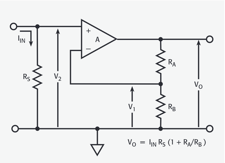
Tip: Choose a DMM that uses an active shunt technique to achieve both high signal-to-noise ratio and a fast response time for your measurement.
Measuring Transmit and Receive Current
Transfer and receive (Tx/Rx) events on an IoT device consume the largest amount of power. Depending on the RF protocol selected for your application, the Tx/Rx current spans from below tens of milliamps to hundreds of milliamps or higher. Ammeters, DMMs, current probes, or sense resistors and an oscilloscope voltage probe are the conventional instruments used to measure current in this range.
Although current probing eliminates the need to “break” the circuit, which is required in most ammeter configurations, there are additional offset compensation and measurement consistency issues to be considered.
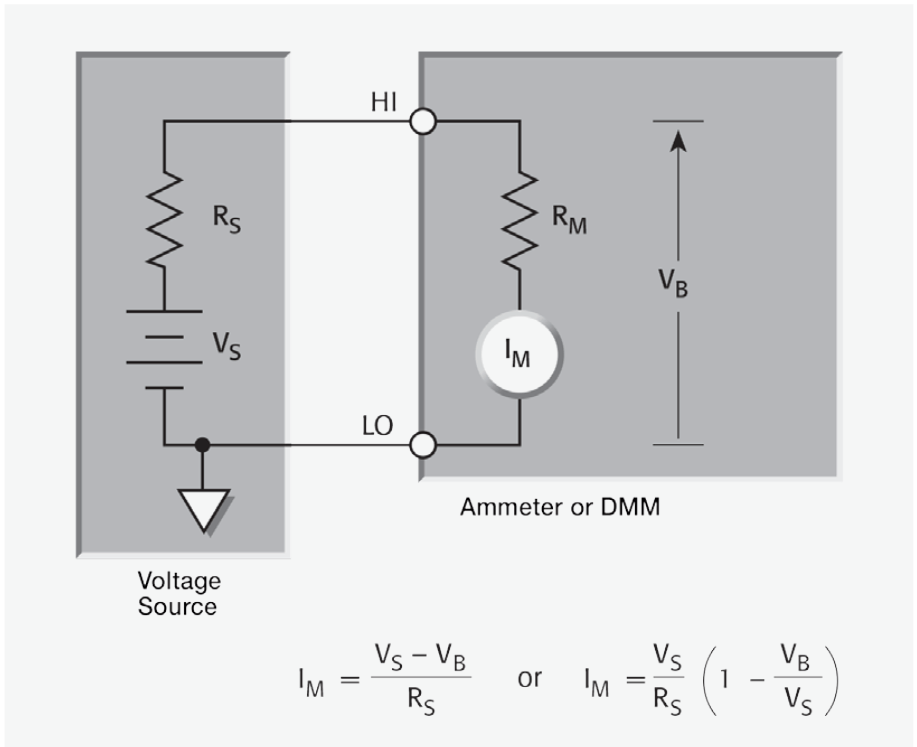
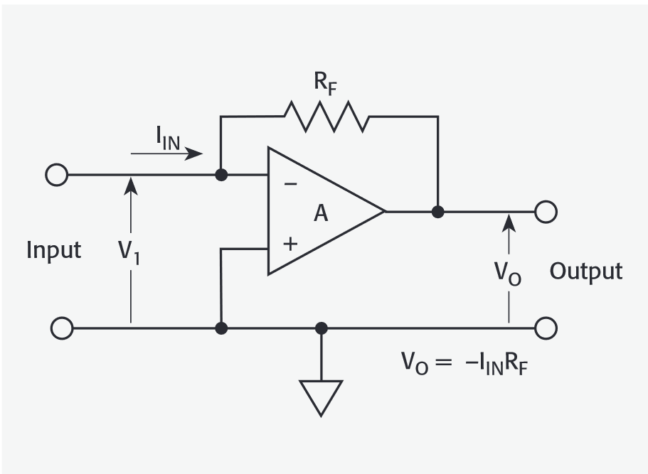
Ammeters use either the shunt ammeter or the feedback ammeter technique. One of the main considerations in a shunt ammeter is voltage burden - the voltage drop across the input terminals of an ammeter. It measures current by converting the input current into a voltage by means of shunt resistance similar to using a sense resistor with a voltage probe. A shunt ammeter has higher voltage burden and lower sensitivity than feedback ammeters.
A feedback ammeter is more sensitive to capacitance from the device under test and its connection to the instrument, and more susceptible to oscillation and unstable readings.
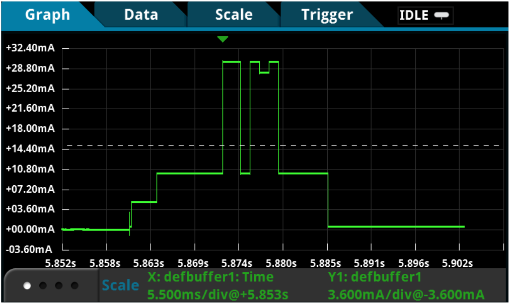
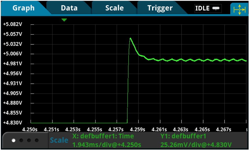
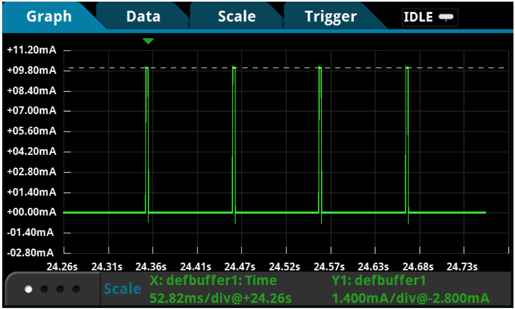
Capturing Short Transients and Fast Transitions
An active IoT device operation is often short and sporadic yet complex with multiple modes of operation involved. For example, when a device wakes from sleep to active mode, it often takes microseconds to transition from sleep to standby before entering the active mode, and the waking-up process can be difficult to capture using conventional ammeters.
Most ammeters or basic DMMs are DC instruments with very slow reading rates. Although many DMMs specify number of power line cycles (NPLC) to indicate the window in which the data is captured, it does not include data processing overhead. The overall time dictates the instrument’s readiness for the next reading. Unfortunately, fast transients are easily lost in the processing overhead.
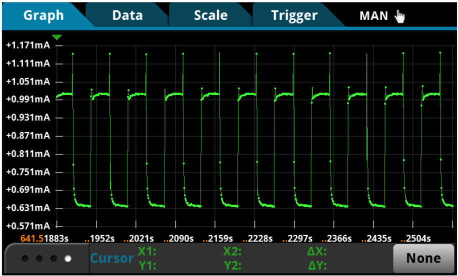
Sample rate is how often an instrument can sample the voltage or current and determines how much waveform detailit can capture. The faster you sample, the less information you’ll lose and the better reconstruction of the original waveform under test you can accomplish. According to the Nyquist or Sampling Theorem, a signal must be sampled at least twice as fast as its highest frequency component to accurately reconstruct it and avoid aliasing (undersampling.)
However, Nyquist is an absolute minimum – it applies only to sine waves and assumes a continuous signal. For fast transient events in IoT device operation, twice the rate of the highest frequency component is simply not enough. Some DMMs specify a sample rate of 50kSamples/s. But, at 50kSamples/s, or 20µs per sample, you’ll easily miss small transients that last even tens of microseconds.
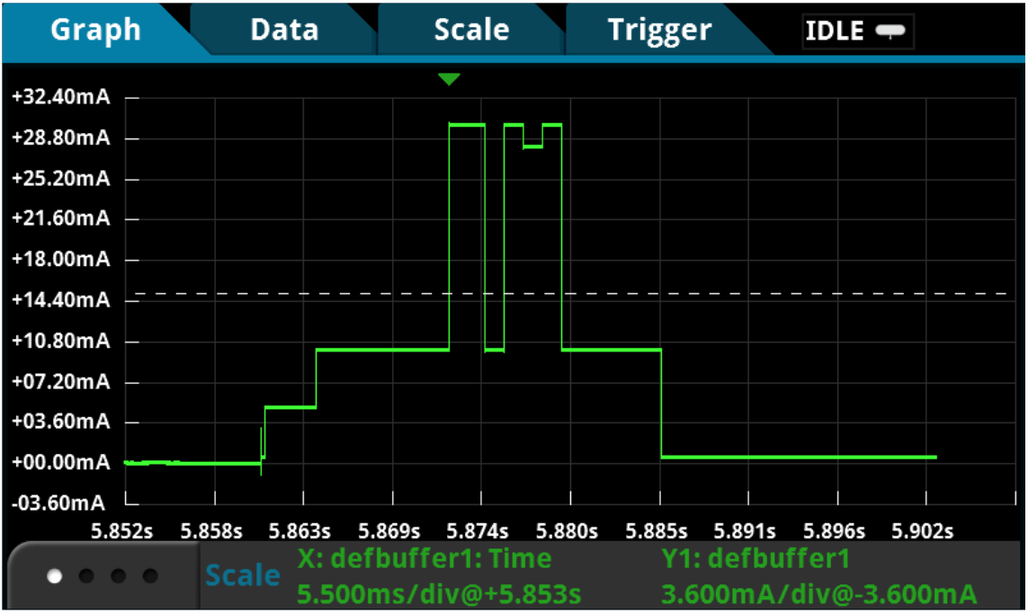
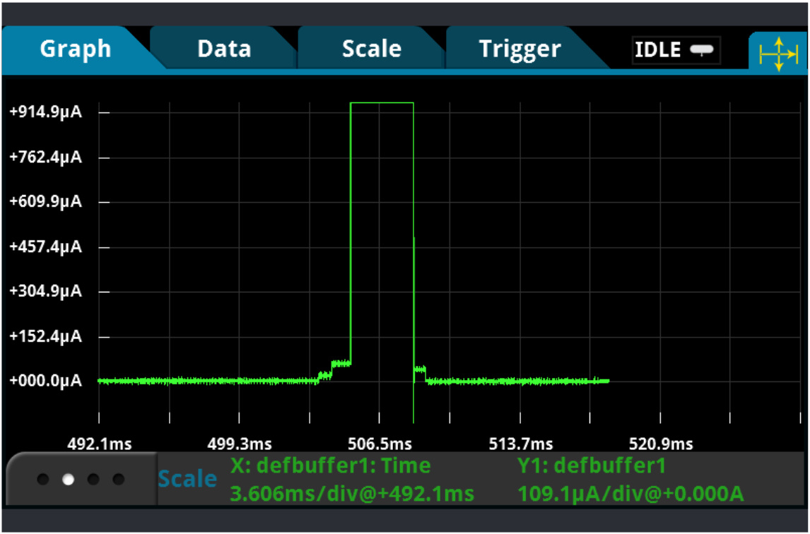
Tip: Choose a high-speed sampling DMM that can sample both voltage and current at 1MSamples/s to capture every detail in your waveform.
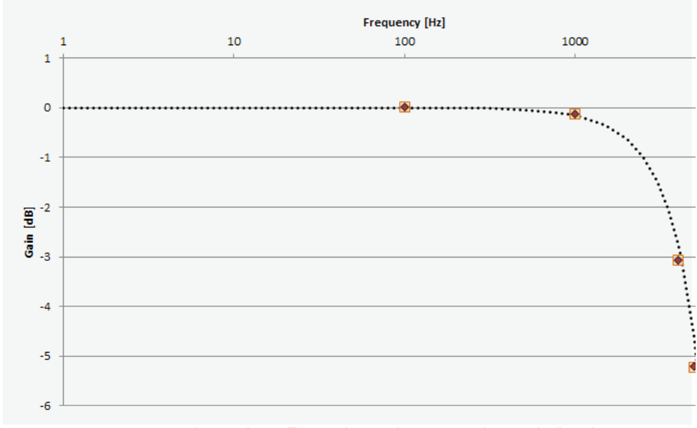
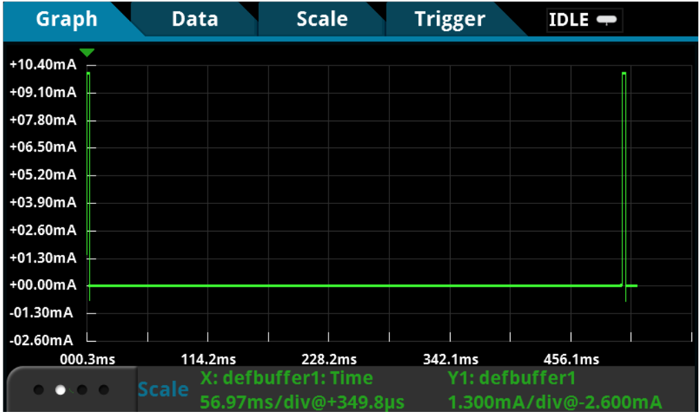
Ensuring Sufficient Measurement Bandwidth for Your Sample Rate
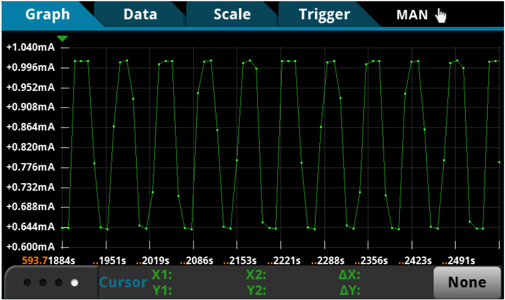
Selecting an instrument for capturing short transient events such as the “wake up” profile based on sample rate alone is not sufficient. Instrument bandwidth also limits the analog signal being sampled. If bandwidth is too low, your instrument will not resolve high-frequency changes before the analog-to-digital conversion takes place. Amplitude will be distorted. Edges will slow down. Details will be lost.
Oscilloscopes are perfect for capturing fast transients, but current probes do not have the sensitivity necessary for the entire dynamic range of many IoT applications. The waveform displayed will reflect the noise floor of the scope and probe rather than the operation of the device.
Most ammeters, DMMs, or specialized instruments with the ability to sample or digitize are limited by the instrument’s analog bandwidth. The details lost due to the 10kHz bandwidth are not recoverable at 200kSamples/s sample rate.
The bandwidth of your instrument combined with its sample rate determines the smallest fast transient of your IoT device.
Tip: Consider a high-speed sampling DMM with sufficiently high analog measurement bandwidth for your waveform.
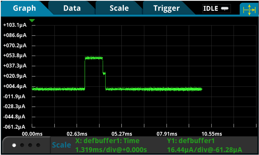
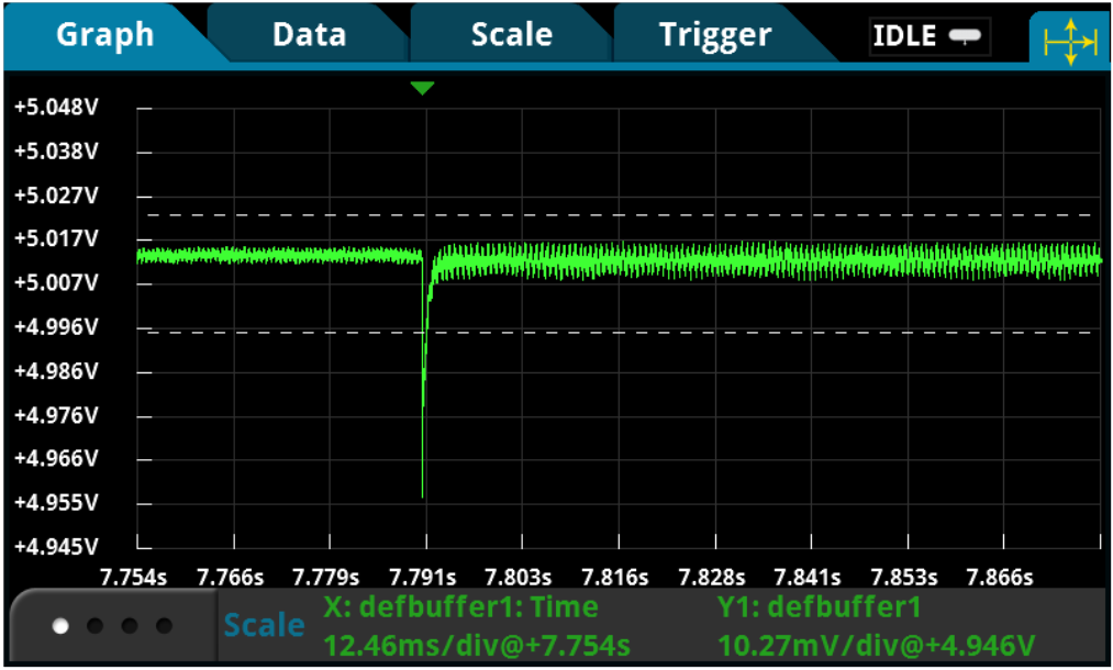
Triggering to Isolate Specific Events
Depending on the application, IoT device operation can involve extremely short bursts of events over a long interval, or a complex state operation where multiple events are included. To analyze these details, triggering is required to scrutinize specific parts of a complex and extended waveform.
Conventional current measuring instruments simply do not offer the capability to isolate specific details. Even slightly sophisticated instruments may only provide a basic oscilloscope trigger mechanism, such as edge trigger or level trigger. In many scenarios, the waveform-oriented edge or level trigger are simply inadequate due to trigger accuracy, trigger latency, trigger skew, and jitter. Plus, low level waveforms at microamp range or lower can significantly impact trigger accuracy depending on the trigger acquisition implementation in the instrument.
Often, the signal and the trigger acquisition are on different paths. Trigger accuracy relies on the sensitivity of the trigger acquisition and can lead to faulty triggering if the instrument cannot react precisely to the trigger event. Trigger latency is an inherent delay between the time the trigger event has been sensed and acquisition of the signal has begun. Long trigger latency can cause an incorrect indication of when the trigger event occurred.
For more challenging waveforms, advanced triggering, such as pulse width, logic trigger, A-B sequence trigger, and synchronous external trigger is preferable. Specialized triggers can respond to specific conditions and make elusive events easy to detect. This wide range of trigger options available on scopes can be made ineffective by the lack of accuracy and sensitivity from current probes.
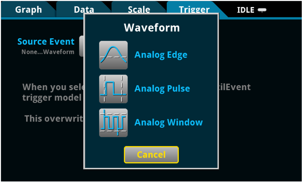
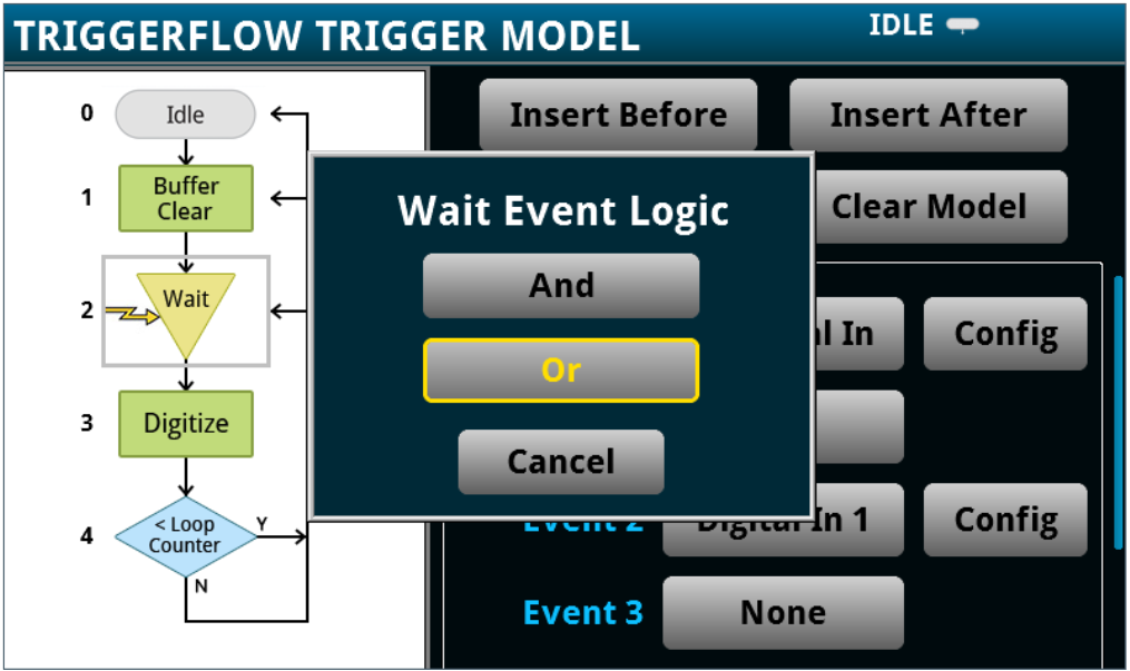
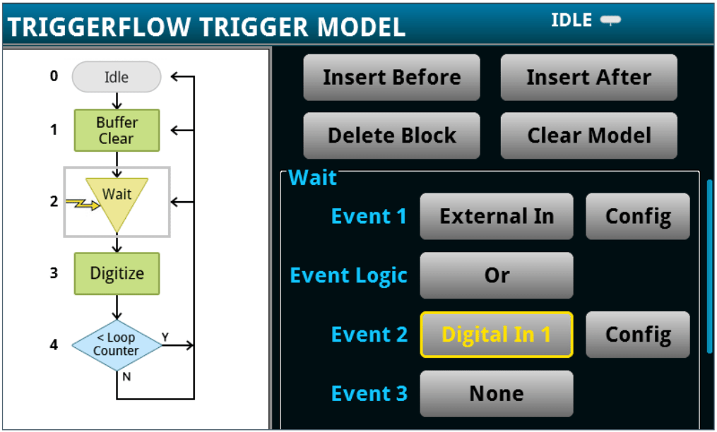
Tip: Choose a high-speed sampling DMM that allows you to create advanced triggering mechanisms similar to those found on a typical oscilloscope.
Recording Device Operation Over Extended Time Intervals
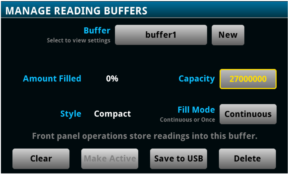
Monitoring device operation for power consumption testing over an extended period is an important and necessary practice. You may need the instrument to log current over a few seconds, a few hours, or even days.
Most general purpose DMM instruments are not equipped with internal data storage that is large enough for these tests. Some specialized voltage and current measuring instruments that can store up 256k readings will reach capacity very quickly at a higher sample rate. Scopes are designed to examine extremely short and extremely complex activities by sampling at hundreds of Mega to several Giga samples per second. Because of the complexity of the waveform, these instruments are not ideal for trending data over time.
If you’ve faced data loss due to a power interruption or simply want to log data beyond the internal storage limit, streaming data live or transferring data post acquisition to an external storage device can be a huge benefit. Retaining data after unexpected external factors have occurred can save time and effort.
Tip: Use a high-speed sampling DMM that is equipped with an internal data buffer for storing 27 millions of readings.
Tip: Use a high-speed sampling DMM that allows real-time data-streaming to an external device or a computer
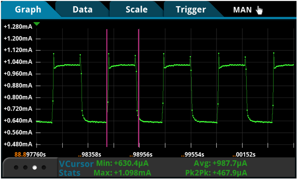
Analyzing Power Consumption from Complex Waveforms
Power management is at the center of IoT design. However, to perform accurate power analysis, you need instruments that not just make the measurement but also automatically evaluate the waveform based on its design requirements.
But, conventional instruments are not solution oriented. Many ammeters can only acquire current readings. Many DMMs may store only a set of current or voltage readings. Some specialized instruments may provide basic statistics such as minimum, maximum, and average. Current probing used with an oscilloscope offers more sophisticated numerical calculation tools such as RMS calculations, duty cycle, and other math operations.
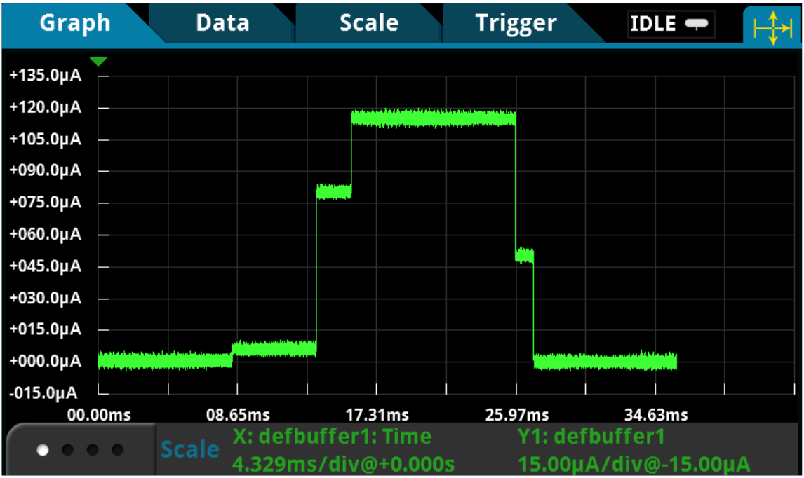
To accommodate the rapid and varying nature of the waveform, instruments with a graphical display are ideal for capturing IoT device operation and provide the opportunity to immediately “see” device operation. Advanced features like measurement “gating” that allow you to constrain the measurements to the screen area or cursors that enable additional control let you gain quicker and deeper insight into the operation of your IoT device.
Since the user interface is a large part of the ‘time-to-answer’ calculation, it should be intuitive, and responsive and react quickly to changing events. Even occasional users should be comfortable and confident with the instrument, while full-time users find easy access to advanced features.
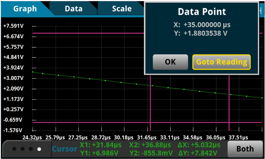
Tip: Consider a graphical sampling DMM that is able to simultaneously capture and display your device operation, as well as perform automated calculations on complex waveforms.
Supplying an Accurate Voltage to Your Device
Low power IOT devices, such as wearable devices, other types of portable products, and industrial monitoring devices that must be in remote locations, operate on batteries that are typically in the 3V to 4V range. At some point in the battery’s discharge cycle, the device will turn off due to the battery’s insufficient output voltage to power the device. To maximize the operating life of the product, it’s important for this low voltage, turn-off threshold to be accurately characterized. Since the device operates over a narrow and small voltage range, the source used to test and power the device needs to have good accuracy. This is especially important in determining the low voltage turn-off threshold.
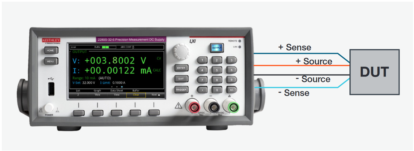
To ensure that the voltage is accurately applied to the load, you should use a power supply that has remote sensing, as shown in the sidebar image.Although the devices draw very low current most of the time, even small losses in the power supply test leads can cause errors when the supply voltages are low. Furthermore, when the device is transmitting, it can draw amps of current, which can cause millivolt voltage drops in the test leads.
Tip: Since these devices operate at low voltages, it’s important that the source used to power and test the device does not negatively affect the device. Noise from a power supply can be a potentially significant portion of the 3V to 4V applied to the device. Use a precision measurement, low noise power supply
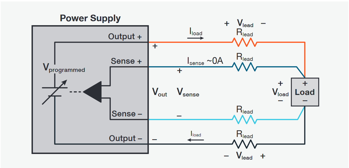
No matter how accurate your power supply output is, you cannot guarantee that the programmed voltage is the same as the voltage at the DUT’s terminals. A power supply without sense leads regulates its voltage at its output terminals. However, the voltage you want regulated is at the DUT’s power inputs. The power supply and the load are separated by lead wires that have resistance, RLead; thus, the voltage at the load is:
V Load = VOut – 2 x VLead = VOut – 2 x ILoad x RLead
The remote sensing technique, using two sense lines, automatically compensates for the voltage drop in the leads by extending the power supply feedback loop to the load. The voltage at the load is fed back to the power supply by the sense leads and ensures that V Load = VProgrammed.
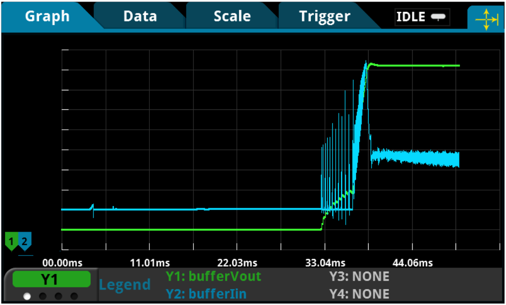
Providing a Stable Voltage for All Device Operating Conditions
To fully test a portable, low power IoT device, you need a power source that can be controlled. Since a battery cannot be controlled or maintain any specific voltage, a power supply must be used to test the device.
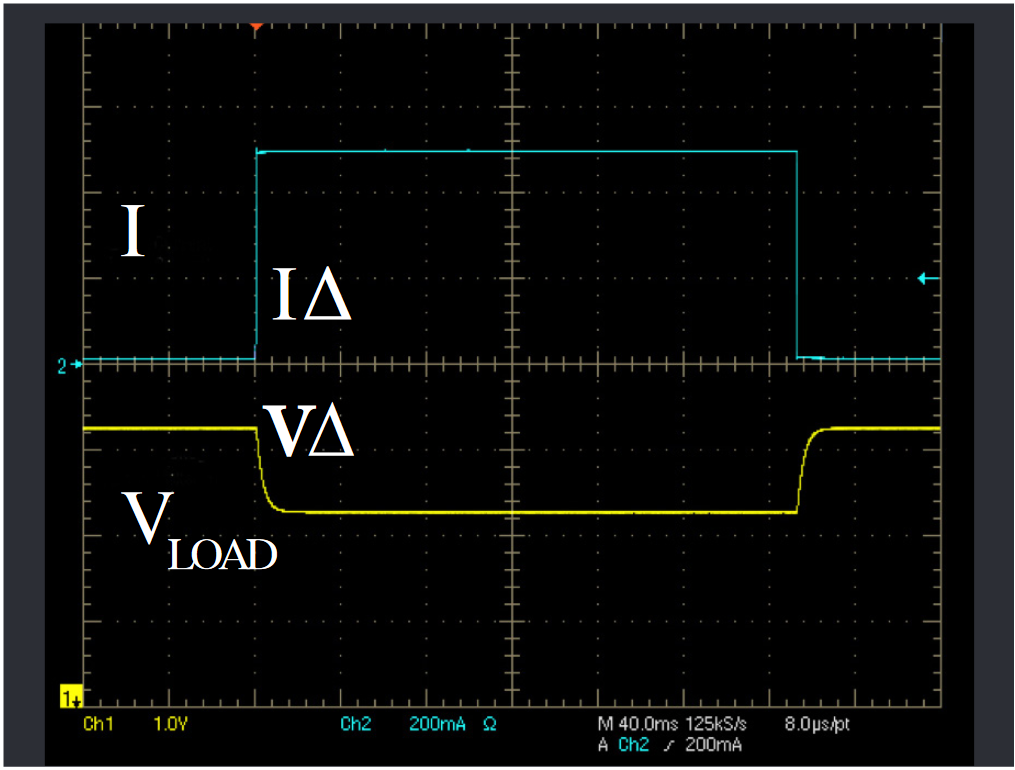
However, as the IoT device transitions from sleep mode or standby mode to a transmitting mode, the load current can change from milliamps to amps - a 1000% load change – in just microseconds!
Tip: For testing portable, wireless devices, look for a power supply with fast transient response and evaluate it to ensure it will not cause the device-under-test to operate poorly or turn off when the device transmits.
A fast, large load change creates a problem for a power supply and for testing an IoT device:
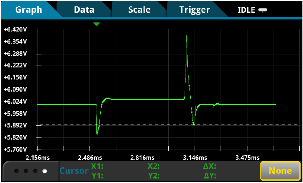
- While the error-correction circuitry is detecting the new load current and adjusting the supply to maintain the programmed output voltage, the voltage is dropping.
- Incorrect measurements on the device can be made while the voltage is low.
- If the voltage drops below the device’s low battery turn-off threshold and remains below that threshold level long enough for the device to detect the low level, the device will turn off.
To avoid this undesirable condition, use a power supply with a fast response to load changes below 100µs for a stable output during all operating states of a device.
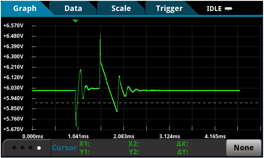
The transient response specification defines how quickly a power supply can respond to load changes. Power supply manufacturers specify their transient response based on a definition developed well before the explosion in the market for portable wireless products. Transient response is typically defined as the time for the power supply to recover to close to its original voltage when the load changes by 50%. Portable wireless devices will have load changes up to 1000% or more. Power supplies do not specify transient response for such a difficult condition.
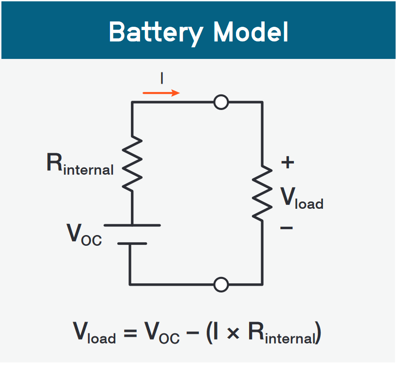
Replicating Battery Output Characteristics Accurately
One way to assess battery life is to use an actual battery to test the IoT device and determine the amount of time the device remained powered. That leads to two problems:
- Waiting for the battery to discharge can be very time consuming and delay development work.
- This test method is not precise, and specific test conditions are difficult to replicate.
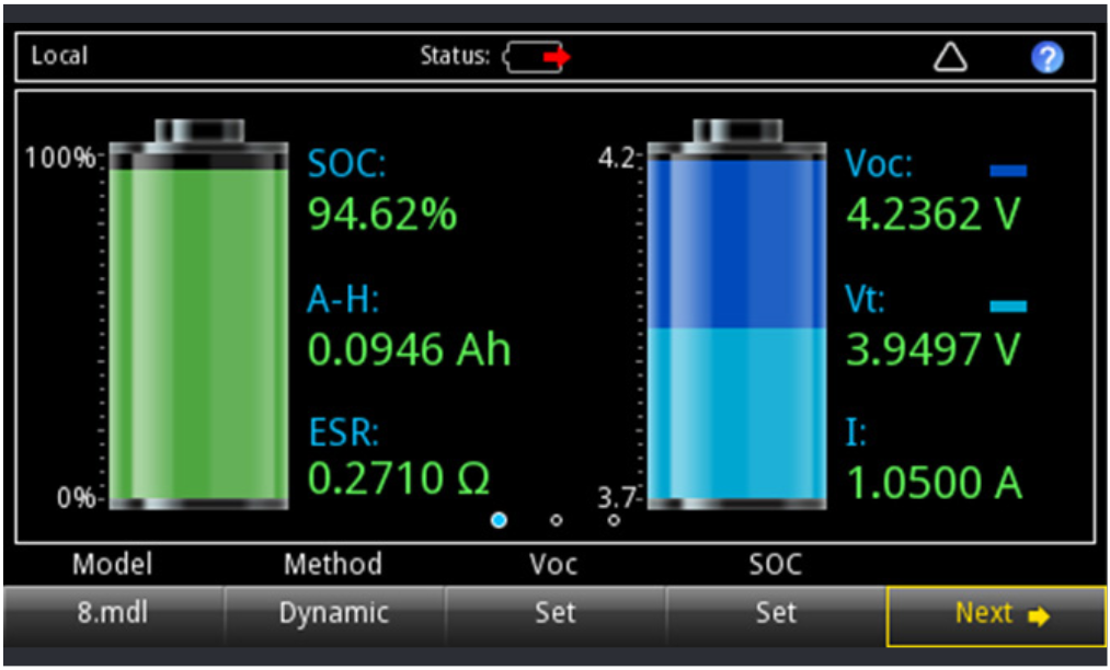
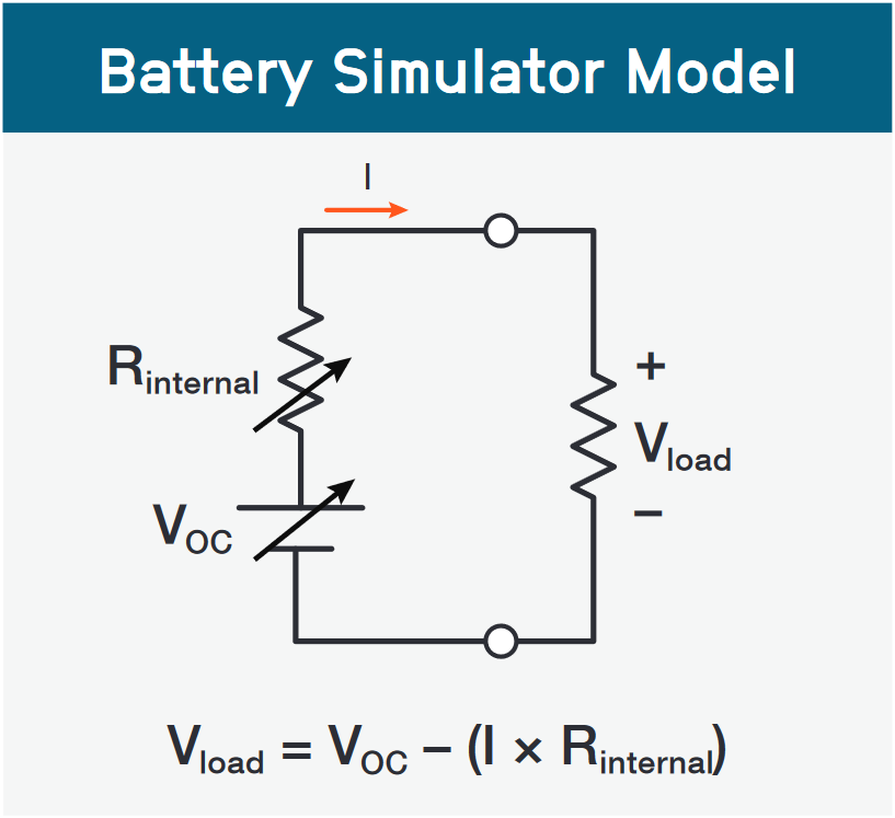
A more ideal solution for testing your IoT device under the most realistic conditions is using a power source that simulates a battery. This solution allows you to test your design under a wide range of conditions from full battery charge to near complete discharge. If you need to select a battery type, then being able to simulate different types of batteries is essential.
Tip: Look for a battery simulator that does more than just simulate a battery’s internal resistance at a single point in time. Ideally, choose a battery simulator that can model the battery dynamically over its entire discharge cycle and uses a model that includes the state-of-charge and the amp-hour capacity, as well as the internal resistance.