與我們聯絡
與 Tek 業務代表即時對談。 上班時間:上午 6:00 - 下午 4:30 (太平洋時間)
請致電
與 Tek 業務代表即時對談。 上班時間:上午 8:30 - 下午 5:30 (太平洋時間)
下載
下載手冊、產品規格表、軟體等等:
意見回饋
Sequencing Power Supply Outputs with the MP5000
Sequencing Power Supply Outputs with the MP5000
Introduction
Power supply output sequencing is the process of controlling the order and timing of when voltage is supplied to a device under test (DUT) using multiple power supply channels. Many modern electronic devices, such as ASICs, FPGAs, and microprocessors, often require multiple power rails with precise sequencing timing, and voltage accuracy during device power-up and power-down. Improper sequencing or unstable voltage levels can lead to device malfunction or permanent damage. The Tektronix MP5000 Modular Precision Test System, paired with the MPSU50-2ST power supply module (PSU), offers a robust and flexible solution for powering up and down complex devices safely and efficiently. This technical brief outlines best practices for power rail bring-up and bring-down using the MP5000.
Challenges in Power Rail Bring-Up and Bring-Down
Improper power rail power-up and power-down can lead to 2 main failures during testing:
- Incorrect power on order leading to unpredictable device states
- High inrush current causing damage to the device
For example, a field programmable gate array (FPGA) contains multiple power rails that control power to core logic, I/O and auxiliary circuits. If the I/O circuits are powered on before the core logic control, those pins may be in an unpredictable state, which could lead to test failures or damage. Proper power on sequencing ensures that each component is powered in a known, expected order
Devices that have capacitive elements are at risk of drawing high inrush current when the power supply is turned on and attempts to rapidly change the voltage level. This high current can damage devices or nuisance trip protection mechanisms such as over current protection (OCP) or over voltage protection (OVP) that shut the power supply off. This current spike can be mitigated by controlling the point at which the supply turns on and the rate at which it ramps to the output level or the slew rate.
Often to achieve precise output sequencing timing needed, externally circuitry or devices need to be added to the circuit, such as a sequencer IC, PMIC, or by putting FETs in series with each output. Adding external circuitry or devices to the circuit adds significant complexity to the test setup. The MP5000 and MPSU50-2ST simplifies device power on and off by allowing for precise sequencing timing via its configurable trigger model, having programmable slew rate to avoid inrush current, and overvoltage and overcurrent protection to turn off the power supply if the set voltage or current threshold is exceeded.
Output Sequencing Using the MPSU50-2ST
Preventing DUT damages requires a 2 part solution in the power supply: controlling when each channel turns on and how fast each channel reaches the set voltage. For basic bench power supplies, this requires complicated external circuitry and additional programming, adding to cost and system development time. The MP5000 test system uses a customizable TriggerFlow™ trigger model and programmable slew rate settings to precisely time and control the MPSU50-2ST 50 W, 2 channel power supply module.
The following example shows how to create a trigger model to sequence 3 MPSU50-2ST modules in an MP5103 mainframe. Each module contains two channels that operate independently, so a single system can power up to 6 independent power rails. Using remote sense ensures that the voltage at the power rail is accurate regardless of lead resistance.
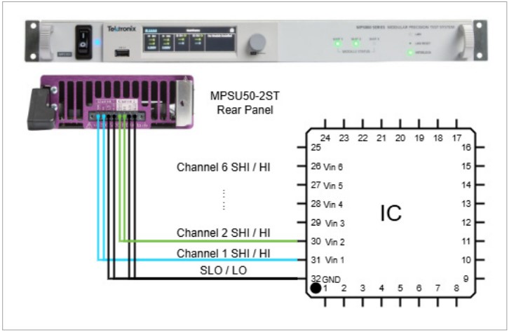
Figure 1: MPSU50-2ST Connections to DUT
For this example, the channels are each turned on to 5 V with the following delays:
| Channel Number | Turn On Delay (ms) | Turn Off Delay (ms) |
|---|---|---|
| 1 | 0 | 25 |
| 2 | 5 | 20 |
| 3 | 10 | 15 |
| 4 | 15 | 10 |
| 5 | 20 | 5 |
| 6 | 25 | 0 |
They are turned off in reverse order. They are also configured to use the max slew rate of 10 kV/s to turn on and off as fast as possible.
The trigger model controls the timing of the power supply levels. The power supply channels are turned on to a level of 0 V before initiating the trigger model to engage the output disconnect relays before turning on. We also configure a list sweep that consists of the desired output level that the trigger model uses to turn on the channel.
The turn-on trigger model and turn-off trigger models are the same and this trigger model must be created for each channel. A wait block in the beginning ensures that all trigger models on all channels are started at the same time. In this example, we use a trigger generator event, which is stimulated using the trigger.generator[N].assert() command. However, this can be modified to use another event such as digital I/O.
The second block is the delay time for the channel to turn on. The final block is a source action block that sets the power supply to the desired level, in this case 5 V. The power supply immediately slews to this new level when the block is executed.
The channels remain on until the turn off trigger model is initialized. It repeats the same process with the opposite delay times. These trigger models are shown in Figure 2.
Since the sweep table has been configured for turn on levels and we are using 2 separate models, we have used a source output block to turn the output off. However, the sweep table can be used if desired in a single trigger model or with a source action skip block before the delay.
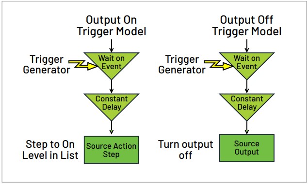
Figure 2: Channel Turn On/Off Trigger Model
Figure 3 shows a scope capture of all 6 channels turning on and off with a 5 ms interval. The code used to generate this example can be found on the Tektronix Github.
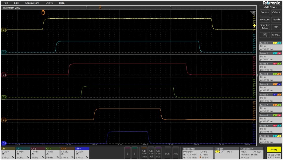
Figure 3: Scope Capture of Output On and Off Sequence 6 PSU Channels
This process can be expanded to multiple mainframes either by triggering through digital I/O lines or by using TSP-Link™. TSP-Link is a high-speed communication and trigger bus that can sync TSP-enabled mainframes within 500 ns. Simply switching the wait event at the beginning of each trigger model to be a TSP-Link trigger and asserting a trigger from the master node allows as many as 32 mainframes to begin their trigger models at the same time.
Conclusion
Multichannel output sequencing with precision timing is needed to turn on and turn off many of today’s complex electronic devices. The MP5103 and MPSU50-2ST provides a comprehensive solution for safe and controlled power rail bring-up and bring-down in complex electric devices. With the TriggerFlow trigger model, programmable slew rate, and overcurrent and overvoltage protection, engineers can confidently power up and power down their devices without having to worry about device damage.