與我們聯絡
與 Tek 業務代表即時對談。 上班時間:上午 6:00 - 下午 4:30 (太平洋時間)
致電
請致電
與 Tek 業務代表即時對談。 上班時間:上午 8:30 - 下午 5:30 (太平洋時間)
下載
下載手冊、產品規格表、軟體等等:
意見回饋
H500 / SA2500
Spectrum Analyzer Datasheet
Tektronix 不再銷售此產品規格表上的產品。
檢視 Tektronix Encore 以取得檢修測試設備。
檢查這些產品的支援和保固狀態。
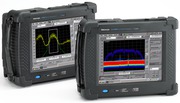
The H500 and SA2500 will quickly scan the RF environment, classify the known signals, and help you locate the unknown signals with their field-proven signal hunting tools. Featuring real-time DPX™ Live RF spectrum display technology, the H500 and SA2500 offer practical solutions for discovering transient events that slip past conventional spectrum analyzers. The H500 and SA2500 are a great choice for general-purpose spectrum measurements and ideal signal-hunting tools.
Notice to EU customers
This product is not updated to comply with the RoHS 2 Directive 2011/65/EU and will not be shipped to the EU. Customers may be able to purchase products from inventory that were placed on the EU market prior to July 22, 2017 until supplies are depleted. Tektronix is committed to helping you with your solution needs. Please contact your local sales representative for further assistance or to determine if alternative product(s) are available. Tektronix will continue service to the end of worldwide support life.
Key features
- Scan
- Revolutionary DPX™ Live RF spectrum display technology with DPX Spectrum Mask provides intuitive understanding of live RF signals using colors based on frequency of occurrence, processing up to 10,000 spectrums/sec with a 100% Probability of Intercept (POI) to capture pulsed signals, radar emissions, hopping signals, and any other intermittent signals with a minimum duration as brief as 125 μs
- Benchtop spectrum analyzer performance in a ruggedized handheld battery-operated field unit offers better than 70 dB spurious free dynamic range (SFDR), guaranteed ≤ -95 dBc/Hz at 10 kHz offset phase noise specifications from 10 kHz to 6.2 GHz
- Excellent sensitivity for detecting very low-level signals with -153 dBm DANL at 10 Hz RBW (equivalent to -163 dBm/Hz) such as RF bugs and unauthorized transmitters
- LAN interface for remote control and unattended monitoring stations for spectrum awareness
- Classify
- Built-in classification capability for WLAN, GSM, W-CDMA, CDMA, ATSC signals makes quick and simple identification of legitimate signals
- Flexibility to edit, upgrade, and share signal databases and signal classification database using CSV file formats
- Ability to export I/Q data into CSV, MATLAB®, and IQT format for additional post-analysis
- Locate
- Rapid targeting of signals with field-proven signal hunting, mapping, and documentation tools
- Hunt outdoor signals with built-in GPS receiver by plotting measurements directly into GPS geo-referenced maps such as Pitney Bowes Mapinfo, Google™ Earth, Microsoft® MapPoint®, Bitmap, and many others
- Improved spectrum awareness with high-accuracy measurement synchronization and time stamping
- Hunt in-building signals with a single-touch Tap-and-Walk-and-Tap interface
- Backlit display, viewable in direct sunlight, and extended battery performance with hot-swappable dual batteries
- Rugged design per MIL-PRF-28800F
Applications
- Spectrum management
- Spectrum monitoring and surveillance
- Interference detection and troubleshooting
- Signal hunting
- Signal identification
- Signal intelligence (SIGINT)
- Homeland Security
Interference troubleshooting has never been so easy
Evolving digital RF communication standards pose an unprecedented challenge to the surveillance and security community. Identification of unknown signals and determining their precise location has traditionally been accomplished using a combination of lab-grade spectrum analyzers, handheld spectrum analyzers, oscilloscopes, and offline analysis capabilities using PCs. When lab equipment is used in the field, several limitations appear. Such instruments are not meant for field use, can be easily damaged, are not portable, and require AC power. Signal classification using these systems often requires a lot of prior knowledge about these signals, particularly when they are digital. With such systems the unknown signals can be difficult or impossible to identify.
With field-ready, rugged hardware featuring DPX Live technology, outstanding displayed average noise level (DANL), spurious free dynamic range (SFDR), phase noise, and easy LAN networking capability in a handheld unit, the H500 and SA2500 are a great choice for general-purpose spectrum measurements and ideal signal-hunting tools.
Scan
By scanning the RF spectrum users can spot which signal emitters are in the area. Signals with significant power are usually candidates for further analysis, as are signals that are present infrequently. By color-coding events based on the rate of occurrence, the DPX™ Live RF spectrum display provides unparalleled insight into the behavior of signals. Performing 10,000 spectrum updates per second, transients as brief as 125 μs can be “frozen” in the frequency domain. This offers tremendous improvement over swept analysis techniques.

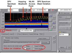
DPX Spectrum Mask captures and logs spectrum violations with options of warning alarm, pausing test, export screen, and result save
Signals that are present in the spectrum today but were not there yesterday are of particular interest. Reference signals can be stored and deviations from this reference can be quickly identified using the trace math feature. The H500 and SA2500 make analysis easier by quickly logging signals that are weak, bursting, hopping, time multiplexed, or intentionally random. It takes advantage of the FFT-based spectrum analysis capability to allow users to see the true shape of the signal, even when it is bursting. Masks can be automatically created from traces captured earlier. You can compare this mask to the current trace and if a mask violation occurs, the trace is logged. Finally, when the spectrogram is paused, you can scroll through the spectrogram’s time axis and view the results.
Classify
Once signals of interest are found, it becomes necessary to identify and classify each of them. Are they authorized, legal signals, or are they illegitimate, malicious signals? Digital signal classification can be a particularly difficult part of the signal hunter’s job requiring extensive knowledge of signal characteristics. The signal may be weak, subject to fading or intermittent conditions. In addition antenna position may be suboptimal. All of this makes classification of signals more challenging when using traditional signal identification tools.
The H500 and SA2500 with Option EP2 offer expert systems guidance to aid the user in classifying signals. It provides graphical tools that allow users to quickly create a spectral region of interest, enabling users to identify and sort signals efficiently. The spectral profile mask, when overlaid on top of a trace, provides signal shape guidance while frequency, bandwidth, channel number, and location are displayed allowing for quick checks.
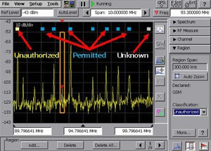
Color-coded signal classification database can be saved, recalled, imported, exported, and shared to keep track of spectrum activities at different locations
Locate
Once the signal has been identified as a threat, the H500 and SA2500 provide various field-proven signal hunting tools to locate the offending signals. For the easier-to-find signals, the signal strength meter produces tones that vary with pitch as a function of the strength of this signal. This allows the operator to look for signals while watching their surroundings, not the screen.
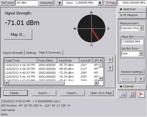
Use Direction Finding display - use compatible antennas and field strength measurements to find the likely directions to signals of interest. Results can be sent to the Mapping application for further geolocation analysis.
For signals that are harder to find, such as signals influenced by multipath, fading, low signal strength, etc, the H500 and SA2500 provide several signal mapping tools to facilitate hunting for these signals. Analyzing mapped signals is a quick way to find signals that can be difficult to find otherwise. The mapping capability is also a way to document what you have found. Traces can be recorded on a map either manually or automatically. Built-in GPS can automatically record signal position and time data as the operator moves. For indoor use, a unique tap-and-walk interface provides signal mapping capability. Color-coded icons automatically record the relevant measurements based on preset thresholds for acceptability.
Most importantly, new capabilities enable the H500 and SA2500 to use a 'smart' antenna with electronic compass bearing output to automatically add the antenna direction to measurement results. This includes compatibility with the Poynting DF-A0047 Direction Finding antenna through a USB connection.
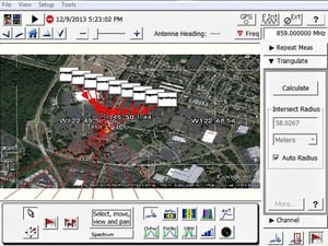
Locate interference with integrated mapping solution and triangulate multiple measurements with resulting areas of uncertainty
The integrated iMap software in the SA2500 and H500 provides triangulation capability from 2 or more measurements. This includes automatically drawing a circle on all intersections from 2 or more measurements that are within a specified radius. Additionally, an azimuth measurement is included for the signal of interest. This can help easily locate interfering signals in the field.
Performance you can count on
Depend on Tektronix to provide you with performance you can count on. In addition to industry-leading service and support, this product comes backed by a one-year warranty as standard.
Specifications
All specifications are guaranteed unless noted otherwise. All specifications apply to all models unless noted otherwise.
Model overview
| Model | Real-time bandwidth | Frequency range | Minimum event duration for 100% POI | SFDR (typical) |
|---|---|---|---|---|
| SA2500 | 20 MHz | 10 kHz - 6.2 GHz | 125 μs 1 - 500 μs | |
| H500 | 20 MHz | 10 kHz - 6.2 GHz | 125 μs |
1With option EP1 installed
General performance characteristics
- RF input
-
- Operating frequency range
- 10 kHz - 6.2 GHz
- Maximum operating input level
- +20 dBm peak envelope power
This is the maximum input level at which the instrument will meet its performance specifications. For a signal without any amplitude variation, peak envelope power = rms.
- Maximum Input Power without Damage
- 50 Wrms below 3.2 GHz
15 Wrmsbetween 3.2 GHz and 6.2 GHz
- IF output
-
- Output impedence
- 50 Ω
- IF center frequency
- 140 MHz
- IF 3 dB bandwidth
- 24 MHz
- IF Output Level (nominal performance at 0 dBm input)
-
Input frequency IF output level 1 GHz -12 dBm 1.6 GHz -12 dBm 3.6 GHz -10 dBm 4.35 GHz -11 dBm 5 GHz -16 dBm 5.75 GHz -22 dBm
- Internal timebase
-
- Frequency error (factory calibration corrected)
- ±0.5 PPM from 0 °C to 50 °C
±1.0 PPM aging/year
Twenty-minute warm-up period required to meet accuracy specification
- Frequency error (GPS corrected)
- ±0.01 ppm (typical)
- Frequency error (after GPS lock loss)
- ±0.03 ppm, 10 minute interval after lock loss (unit operated for >20 minutes before lock loss and
- External reference input
-
- impedance
- 1500 Ω
- Frequencey range
- 1 MHz up to 20 MHz ± 1 PPM, in 1 MHz steps
- Input level range
- -15 dBm to +15 dBm, 1 MHz to 15 MHz
-10 dBm to +15 dBm, 16 MHz to 20 MHz
dBm levels assume 50 ohm source
- Integrated GPS receiver
-
- Position Accuracy (typical)
- Horizontal: R Altitude: H
- Position Update Rate (nominal)
- 1 update/sec (Latitude/Longitude/Altitude)
Spectrum analyzer characteristics
- Frequency
-
- Span
- 10 kHz to 6.2 GHz (preamp off)
10 MHz to 6.2 GHz (preamp on)
- Center frequency setting resolution
- 1 Hz
- Swept spans (wide scanning)
-
- Span Range
- 20 MHz to 6.2 GHz
- Spectrums per second
- 61 (typical)
- Scan Speed
- 1240 MHz per second (typical)
- Resolution Bandwidth (RBW)
-
- RBW Range
- 10 Hz to 3 MHz (Manual)
10 Hz to 1 MHz (Auto)
- RBW setting resolution
- 1 Hz
- Spectral purity
-
- Displayed average noise level, preamp On
- -153 dBm, 10 MHz to 2 GHz, 10 Hz RBW
-152 dBm, 2 GHz to 4 GHz, 10 Hz RBW
-151 dBm, 4 to 5 GHz, 10 Hz RBW
-145 dBm, 5 to 6.2 GHz, 10 Hz RBW
- Phase noise (entire operating frequency range)
- ≤ -95 dBc/Hz at 10 kHz offset
≤ -95 dBc/Hz at 20 kHz offset
≤ -95 dBc/Hz at 30 kHz offset
≤ -97 dBc/Hz at 100 kHz offset
≤ -110 dBc/Hz at 1 MHz offset
- Residual spurious, preamp Off
- ≤ -90 dBm, 0 dBm attenuator setting
Exception Frequencies:
9 MHz to 19 MHz center frequency
3464 MHz center frequency
4592 MHz center frequency
5374 MHz to 5378 MHz center frequency
6160 MHz center frequency
- Residual spurious, preamp On
- ≤ -105 dBm, 0 dBm attenuator setting
Exception Frequencies:
9 MHz to 19 MHz center frequency
5374 MHz to 5378 MHz center frequency
- Third order IMD
- ≤ -70 dBc for two tones at or below the reference level, preamp Off, all gain settings auto-coupled
- Second harmonic
- ≤ -60 dBc for a single tone at or below the reference level, preamp Off, all gain settings auto-coupled
- Input-related spurious
- ≤ -70 dBc except for Fin= 2.282 GHz ± 20 MHz
The dBc reference for this specification is the total power of all signals at the input of the instrument regardless of the current span
- Input-related spurious, exception frequencies, typical
- ≤ -55 dBc at Fin= 2.282 GHz ± 20 MHz
The dBc reference for this specification is the total power of all signals at the input of the instrument regardless of the current span
- Third order intercept
- ≥ +7 dBm, 0 dB input attenuation, preamp Off
- Spectral display amplitude
-
- Reference level range
- +20 dBm to -160 dBm
- Marker power accuracy
- ±1.75 dB, -50 dBm ≤ input ≤ +20 dBm, preamp off
±3.0 dB, -80 dBm ≤ input
±3.75 dB, -120 dBm ≤ input
Use peak detector for CW-like signals; use average detector for wideband (signal >> RBW)
Accuracy guaranteed for CW signals and span set to 20 MHz or less
- Display modes
-
- Display modes
- Normal – Updates display with each new result
Max Hold – Updates displayed point only if new point > old
Min Hold – Updates displayed point only if new point
Max/Min Hold – Displays a vertical bar between Max Hold and Min Hold
Average – Displays average of N (specified by user) acquisitions
Average is calculated as follows:
Last N values are saved in memory; when a new result is available, the earliest result of the N stored values is discarded, the new result is added to the stored values, and a new average is calculated from the stored values. If the number of results is less than N, then all of the results are averaged together
- Number of averages
- 1 ≤ N ≤ 200
General purpose RF measurement characteristics
- RF channel power measurement
-
- Bandwidth range
- 1 kHz - 20 MHz
- Accuracy
- ≤1.2 dB; +20 dBm to -60 dBm; 1 MHz to 3.2 GHz, preamp off, Ref Level > -35 dBm
≤2.4 dB; -40 dBmto -75 dBm; 10MHz to 3.2 GHz, preamp on, Ref Level ≤ -35 dBm
≤1.8 dB; +20 dBm to -50 dBm; 3.2 GHz to 6.2 GHz, preamp off, Ref Level > -35 dBm
≤3 dB; -40 dBm to -75 dBm; Resolution BW
Specifications apply for default control settings (Auto RBW, Auto Level)
- Occupied bandwidth measurement
-
- Percent Power Inclusion Range
- 50-100%
- RF field strength
-
- Channel bandwidth range
- Same as RF channel power
- Accuracy
- Same as RF channel power
Scan, classify, and locate characteristics
- DPX™ Live RF spectrum display
-
- Spectrum processing rate, nominal
- 10,000 spectrums per second, span independent (H500 standard and SA2500 with Option EP1)
2,500 spectrums per second (SA2500 standard)
- Minimum signal duration for 100% probability of intercept (POI), typical
- 125 μs (H500 standard and SA2500 with Option EP1)
500 μs (SA2500 standard)
- Span Range
- 5 kHz to 20 MHz
- Spectrogram (rising raster)
-
- Spectrum processing rate, nominal
- 20 spectrums per second
- Minimum signal duration for time measurement
- 20 milliseconds (typical)
- Span range
- 5 kHz to 20 MHz
- Trigger
-
- Modes
- Single or continuous, free run or triggered
- Event source
- IF level, external input, or internal timebase
- Types
- Rising edge, falling edge, level above threshold, level below threshold
- Delay
- 0 to 60 s with 1 μs resolution
- Position
- Settable from 0-100%
- IF level trigger
-
- Threshold range
- -160 dBm to +20 dBm
- Bandwidth range
- 5 kHz to 20 MHz
- External trigger
-
- Maximum input level without damage
- ±5 Vpeak continuous
- Minimum high threshold
- 2.0 V
- Maximum low threshold
- 0.8 V
- Minimum High/Low time
- 10 ns
- Impedance
- 10 kΩ
- Coupling
- DC
- Internal timebase trigger
-
- Mode
- Single trigger on time, repeat trigger at interval, or both
- Resolution
- 1 μs
- Measurement result time stamps
-
- Resolution (nominal)
- 1 ms before GPS lock obtained; 1 ns after GPS lock obtained.
- Accuracy - relative (typical)
- ±500 ns time-stamp error between multiple measurement results. Internal GPS reference lock required.
- Accuracy - GPS reference (typical)
- ±1 μs, all measurements except DPX spectrum; ±1 ms DPX spectrum.
Time-stamp error relative to GPS system absolute time reference. Internal GPS reference lock required, identical acquisition bandwidth setting required.
- IQ acquisition time
-
(available in amplitude vs. time measurement)
Span Sample rate Maximum acquisition length 20 MHz 28 Msps 36 ms 10 MHz 14 Msps 73 ms 5 MHz 7 Msps 146 ms 2 MHz 2.8 Msps 365 ms 1 MHz 1.4 Msps 731 ms 500 kHz 700 ksps 1.4 sec 200 kHz 280 ksps 3.6 sec 100 kHz 140 ksps 7.3 sec 50 kHz 72.9 ksps 14 sec 20 kHz 27.3 ksps 37 sec 10 kHz 13.7 ksps 74 sec 5 kHz 6.8 ksps 149 sec
- AM demodulation
-
- Measurement frequency
- As selected
- Minimum input signal level, typical
- -100 dBm
- Audio measurement bandwidth
- 8 kHz
- FM demodulation
-
- Measurement frequency
- As selected
- Minimum input signal level, typical
- -100 dBm
- Maximum signal deviation
- Up to 100 kHz
- Audio measurement bandwidth
- 8 kHz, 15 kHz, 75 kHz, or 200 kHz
- Maximum audio output bandwidth
- 15 kHz
- Signal strength indicator
-
- Input signal level
- -120 dBm, minimum
- Measurement frequency
- As selected
- Measurement bandwidth
- Up to 20 MHz, dependant upon span and RBW setting
- Tone type
- Variable beep rate or variable frequency
- Update rate, typical
- 10 per second
- Mapping
-
- Native map type
- Graticule (.gsf)
- Map types directly supported
- Pitney Bowes MapInfo (*.mif), Bitmap (*.bmp), MPS (collection of GSF maps derived from Open Street Map mapping tiles) 1
- Other map types accepted using PC application iMap converter
- Google™ earth
Microsoft® MapPoint®
USGS DLG (*.opt)
ESRI ArcInfo Shape (*.shp)
Other raster formats (*.gif, *.jpg, *.png, *.tif)
1Maps derived from Open Street Map tiles are © OpenStreetMap contributors. For more information see http://www.openstreetmap.org/copyright.
Power
- Battery life
- 5 hours of continuous Spectrum mode (with optional second battery). Actual life can be higher depending on usage.
Physical characteristics
- Temperature
-
- Operating
- 0 °C to +50 °C specified performance, -10 °C to +50 °C, typical
- Nonoperating
- -40 °C to +60 °C
- With batteries installed
- While charging: 0 °C to +45 °C
Storage (nonoperating): -20 °C to +60 °C
- Humidity
-
- Operating and nonoperating
- 5% to 95% relative humidity (RH) at up to +30 °C, noncondensing
5% to 45% RH above +30 °C up to +50 °C, noncondensing
- Altitude
-
- Operating
- Up to 4,600 meters (15,092 feet)
- Nonoperating
- Up to 12,192 meters (40,000 feet)
- Dimensions
-
- Height
- 25.5 cm. (10.0 in.)
- Width
- 33 cm. (13 in.)
- Depth
- 12.5 cm.
- Weight
- 5.56 kg (12.27 lb.)
- Color display
-
- Size
- 10.4 in. (diagonal), transflective LCD, color
- Resolution
- 640×480 (VGA)
EMC environment and safety
- Electromagnetic compatibility (EMC) compliance
- EN61326-1:2006 and EN61326-2:2006 Product Family Standard for Electrical Equipment for Measurement, Control, and Laboratory Use – EMC Requirements.
- European Union
-
- Emissions
- CISPR11, group 1, class a
EN 61000-3-2
EN 61000-3-3
- Immunity
- IEC 61000-4-2
IEC 61000-4-3
IEC 61000-4-4
IEC 61000-4-5
IEC 61000-4-6
IEC 61000-4-11
- Australia/New Zealand
- EMC compliance in accordance with the ACMA
- USA
- FCC, CFR Title 47, Part 15, Subpart B, Class A.
- Safety compliance
- ANSI/UL610101:2004
Electrical Equipment for Measurement, Control, and Laboratory Use
CSA C22.2 No. 61010.1:2004
Electrical Equipment for Measurement, Control, and Laboratory Use
EN 610101:2001
Safety Compliance Electrical Equipment for Measurement, Control, and Laboratory Use
IEC610101:2001
Electrical Equipment for Measurement, Control, and Laboratory Use
ISA 82.02.01
Electrical Equipment for Measurement, Control, and Laboratory Use
Warranty and calibration
- Warranty
- 1 year on parts and labor
- Recommended instrument calibration interval
- 2 years
Ordering information
Models
- H500
- Real-time spectrum analyzer with DPX™ Live RF spectrum display of 125 μs minimum signal duration for 100% Probability of Intercept (POI) and signal classification capability.
Includes User manual, installation software, AC power adapter, Lithium-ion battery, GPS antenna, flexible monopole antenna, Type-N (m) to BNC (f) adapter, USB A-B cable, tilt stand, soft carry case, audio jack mute plug (mutes all audio output from the instrument speaker), one-year warranty.
- SA2500
- Real-time spectrum analyzer with DPX™ Live RF spectrum display of 500 μs minimum signal duration for 100% Probability of Intercept (POI).
Includes User manual, installation software, AC power adapter, Lithium-ion battery, GPS antenna, flexible monopole antenna, Type-N (m) to BNC (f) adapter, USB A-B cable, tilt stand, soft carry case, audio jack mute plug (mutes all audio output from the instrument speaker), one-year warranty.
Options
SA2500 options
- Option EP1
- Enhances SA2500 DPX™ Live RF spectrum display to 10,000 spectrums/sec and 125 μs minimum signal duration for 100% Probability of Intercept (POI)
- Option EP2
- Enhances SA2500 by adding signal classification to the Spectrum Notes capability. Provides capability to notate (label) regions of RF spectrum. Provides capability to compare bandwidth, channel frequency, etc., to internal tables of standards. Can save a mask (stored display) of user-generated mask to enable spectrum violation measurement. Provides database to store these notation results, along with GPS location and time.
Power plug options
- Opt. A0
- North America power plug (115 V, 60 Hz)
- Opt. A1
- Universal Euro power plug (220 V, 50 Hz)
- Opt. A2
- United Kingdom power plug (240 V, 50 Hz)
- Opt. A3
- Australia power plug (240 V, 50 Hz)
- Opt. A5
- Switzerland power plug (220 V, 50 Hz)
- Opt. A6
- Japan power plug (100 V, 50/60 Hz)
- Opt. A10
- China power plug (50 Hz)
- Opt. A11
- India power plug (50 Hz)
- Opt. A12
- Brazil power plug (60 Hz)
- Opt. A99
- No power cord
Language options
- Opt. L0
- English manual
- Opt. L99
- No manual
Service options
- Opt. C3
- Calibration Service 3 Years
- Opt. C5
- Calibration Service 5 Years
- Opt. D1
- Calibration Data Report
- Opt. D3
- Calibration Data Report 3 Years (with Opt. C3)
- Opt. D5
- Calibration Data Report 5 Years (with Opt. C5)
- Opt. G3
- Complete Care 3 Years (includes loaner, scheduled calibration, and more)
- Opt. G5
- Complete Care 5 Years (includes loaner, scheduled calibration, and more)
- Opt. R3
- Repair Service 3 Years (including warranty)
- Opt. R5
- Repair Service 5 Years (including warranty)
Recommended accessories
Upgrades
- SA2500F Option EP1
- Field Upgrade Kit for Enhanced Performance. Increases the SA2500 DPX™ live RF spectrum rate to 10,000 spectrums/s and 125 μs minimum signal duration for 100% probability of Intercept (POI), typical.
- SA2500F Option EP2
- Field upgrade for enhanced performance. Adds signal classification capability to notable regions of RF spectrum. Provides capability to compare bandwidth, channel frequency, etc., to internal tables of standards. Can save mask (stored display) of user-generated masks to enable spectrum violation measurements. Provides database to store these notation results, along with GPS location and time.


