與我們聯絡
與 Tek 業務代表即時對談。 上班時間:上午 6:00 - 下午 4:30 (太平洋時間)
請致電
與 Tek 業務代表即時對談。 上班時間:上午 8:30 - 下午 5:30 (太平洋時間)
下載
下載手冊、產品規格表、軟體等等:
意見回饋
AWG70001A Arbitrary Waveform Generator--Option AC, Datasheet
AWG70001A Option AC Datasheet
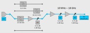
The AWG70001A, with Option AC, provides you with an additional high output amplitude connector. Option AC adds a single-ended AC coupled Planar Crown connector to the front panel of the single channel AWG70001A Arbitrary Waveform Generator. User controls are added to allow switching the output path between the standard Direct output connectors or the AC output connector. When switched to the AC path, additional user controlled amplification and attenuation is added to the signal path.
In AC output mode, you can chose one of the four signal filter paths and set the output amplitude, letting the instrument to automatically set the step attenuators in the selected filter path. For greater control, you can manually set the attenuation of the step attenuators for your selected filter path.
KeyFeatures
- No filter: -70 to +25 dBm at 1 GHz CW calibration frequency
- 11.5 GHz Low Pass: -70 to +25 dBm at 1 GHz CW calibration frequency
- 10 GHz – 14.5 GHz Band Pass: -77 to +18 dBm at 11 GHz CW calibration frequency
- 13 GHz – 18 GHz Band Pass: -90 to +20 dBm at 14 GHz CW calibration frequency
AWG70001A Option AC output specifications
These specifications apply to the optional AC output connector. Refer to the AWG70000 series datasheet for all other instrument specifications.
All specifications are guaranteed unless noted otherwise. All specifications apply to all models unless noted otherwise.
- Output connector
-
Aeroflex/Weinschel Planar Crown Universal Connector System with SMA female adapter
- Number of analog AC outputs
-
AWG70001A: 1
- Type of outputs
- single ended
- Output impedance
- 50 Ω
- Frequency range
-
-
Filter Value No filter 10 MHz to 18 GHz Low pass 10 MHz to 11.5 GHz Band pass (10 to 14.5 GHz) 10 GHz to 14.5 GHz Band pass (13 to 18 GHz) 14 GHz to 18 GHz
-
- Amplitude
-
- Range (for a CW signal at specified frequencies in each path)
-
Filter path Description No filter 25 dBm to -70 dBm at 1 GHz 18 dBm to -77 dBm at 13 GHz Low pass 25 dBm to -70 dBm at 1 GHz Band pass (10 GHz to 14.5 GHz) 18 dBm to -77 dBm at 11 GHz Band pass (13 GHz to 18 GHz) 20 dBm to -90 dBm at 14 GHz 18 dBm to -90 dBm at 18 GHz - Accuracy (at calibration frequency)
-
Filter path Description No filter ±0.5 dB at 1 GHz, ambient 16 °C to 26 °C ±1.5 dB at 1 GHz, ambient 0 °C to 50 °C Low pass ±0.5 dB at 1 GHz, ambient 16 °C to 26 °C ±1.5 dB at 1 GHz, ambient 0 °C to 50 °C Band pass (10 GHz to 14.5 GHz) ±1.5 dB at 11 GHz, ambient 16 °C to 26 °C ±3.0 dB at 11 GHz, ambient 0 °C to 50 °C Band pass (13 GHz to 18 GHz) ±1.5 dB at 14 GHz, ambient 16 °C to 26 °C ±3.5 dB at 14 GHz, ambient 0 °C to 50 °C - Resolution
- 0.01 dB
- Ampitude flatness
- Specifications include the sin(x)/x roll off of the DAC at 50 GS/s.
-
Filter Description No filter ± 3 dB, 10 MHz to 10 GHz
± 4 dB, 10 MH to 13 GHzLow pass ± 3 dB, 10 MHz to 10 GHz Band pass (10 GHz - 14.5 GHz) ± 3.5 dB, 10 GHz to 14.5 GHz Band pass (13 GHz - 18 GHz) ± 4.5 dB from 13 GHz to 18 GHz
-
- Harmonic distortion
- AWG70001A operating at 50 GS/s.
- 2nd Harmonic at output frequency
-
Frequency range Value 1 GHz - 4 GHz > 4 GHz - 3rd Harmonic at output frequency
-
Frequency range Value 1 GHz - 4 GHz > 4 GHz
- Amplifier 1 dB compression
-
- AWG70001A operating at 50 GS/s.
- No filter
Filter Frequency Value No filter 1 GHz > 25 dBm 13 GHz > 22 dBm Low Pass filter 1 GHz > 25 dBm Band Pass (10 to 14.5 GHz) 11 GHz > 22 dBm Band Pass (13 to 18 GHz) 14 GHz > 22 dBm 18 GHz > 20 dBm
- Switching time
- The time required for the attenuators and amplifiers to settle to the specified output amplitude after an amplitude change.
Ordering information
Models
- AWG70001A AC
-
AWG70001A with Option AC
Option AC adds a single-ended AC coupled output connector with additional amplification and attenuation.