
與我們聯絡
與 Tek 業務代表即時對談。 上班時間:上午 6:00 - 下午 4:30 (太平洋時間)
致電
請致電
與 Tek 業務代表即時對談。 上班時間:上午 8:30 - 下午 5:30 (太平洋時間)
下載
下載手冊、產品規格表、軟體等等:
意見回饋
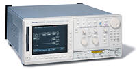
Arbitrary Waveform Generator
AWG615
Tektronix 不再銷售此產品規格表上的產品。
檢視 Tektronix Encore 以取得檢修測試設備。
檢查這些產品的支援和保固狀態。
Features & Benefits
- 2.7 GS/s Sample Rate Simulates Real-world Signals Up To 1.35 GHz
- 2 Markers With 2.1 psRMS (@ 2.7 GS/s, Typical) Jitter Deliver stable Timing to the Device-under-test (DUT)
- 32.4M (32,400,000) or 64.8M (64,800,000) Point Record Length Provide Longer Data Streams
- Analog Bandwidth to 2 GHz (Option 02, Calculated Based on Rise Time) Provides the Highest Signal Fidelity of All High-speed AWGs
- Direct External clock input allows Jittered and non-jittered signals for high-speed data stream timing margin test up to 2.7 Gb/s
- Synchronous operation mode supports two AWG615 outputs (2: analog, 4: marker) synchronization for high data rate wireless and data communication test and optical write channel strategy signal test.
- Waveform Quick Editor with 400 fs Edge Timing Resolution Delivers Output Edge Control with Near Real-time Precision
- Allows two-signal mix function digitally to support disk drive noise performance test and Pre/De-emphasis serial data communication test
- Real-time Sequencing Creates Infinite Waveform Loops, Jumps, Patterns and Conditional Branches
Applications
- Disk Drive Read/Write Design and Test
- Communications Design and Test
- Arbitrary IF and IQ Base-band Signals
- Standard Waveforms for Communications
- Pulse Generation
- High-speed, Low-jitter Data and Clock Source
- Mixed Signal Design and Test
- Real-world Simulations
- Corruption and Enhancement of Ideal Waveforms
- Timing and Amplitude Signal Impairments
- Waveforms Imported from MathCad, MATLAB, Excel and Others
The AWG615 Arbitrary Waveform Generator Delivers World-class Signal Fidelity at 2.7 GS/s to Solve Ever-increasing Measurement Challenges
The AWG615 Arbitrary Waveform Generator Delivers World-class Signal Fidelity at 2.7 GS/s to Solve Ever-increasing Measurement Challenges. New two box synchronous operation function supports 2ch 2.7 GS/s solution.
The AWG615 combines world-class signal fidelity with high-speed mixed signal simulation, a powerful sequencing capability and graphical user interface with flexible waveform editor, to solve the toughest measurement challenges in the disk drive, communications and semiconductor design/test industries.
The built-in signal applications enable you to easily create standard waveforms for disk drive read channels, communications up to 2.7 Gb/s. Also included is AXW100 ArbExpress waveform creation and editing software. This software allows for easy waveform import from oscilloscopes or basic, advanced, and math waveform creation and edit capabilities.
Waveform Mixing Function.

Gigabit Ethernet Application Menu.
Characteristics
Arbitrary Waveforms
Waveform Length - 960 to 32,400,000 points (or 64,800,000 points, option 01) in multiples of four.
Sequence Length - 1 to 8,000 steps.
Sequence Repeat Counter - 1 to 65,536 or infinite.
Run Modes
Gated mode, Event Jump, and Software Jump are disabled in the synchronous operation
Continuous - Waveform is iteratively output. If a sequence is defined, the sequence order and repeat functions are applied.
Triggered - Waveform is output only once when an external, internal, GPIB, LAN, or manual trigger is received.
Gated - Waveform begins output when gate is true and resets to beginning when false.
Enhanced - Waveform is output as defined by the sequence.
Extended Operation
Function Generator
Waveform Shape - Sine, Triangle, Square, Ramp, Pulse, or DC.
Frequency - 1.000 Hz to 270.0 MHz.
Amplitude -
Range: 0.020 Vp-p to 2 Vp-p into 50 Ω
Resolution: 1 mV.
Offset -
Range: -0.500 V to +0.500 V into 50 Ω
Resolution: 1 mV.
DC Level - DC waveform only.
Range: -0.500 V to +0.500 V into 50 Ω
Resolution: 1 mV.
Polarity - Normal, Invert.
Duty Cycle -
Range: 0.1% to 99.9%, Pulse waveform only.
Resolution:
1.000 Hz to 4.000 MHz: 0.1% step.
4.001 MHz to 20.00 MHz: 0.5% step.
20.01 MHz to 40.00 MHz: 1% step.
40.01 MHz to 80.00 MHz: 2% step.
80.01 MHz to 100.0 MHz: 2.5% step.
100.1 MHz to 160.00 MHz: 4% step.
160.1 MHz to 200.0 MHz: 5% step.
200.1 MHz to 270.0 MHz: 10% step.
Marker Out -
Marker1 Pulse Width:
Hi Lo: 20% / 80% of Period.
Marker2 Pulse Width:
Hi/Lo: 50% / 50% of Period, except 100.1 MHz to 160.0 MHz.
Hi/Lo: 52% / 48% of Period, at 100.1 MHz to 160.0 MHz.
Marker Level:
Hi Level: 1V into 50 Ω
Lo Level: 0V into 50 Ω
Waveform mixing operation - Supports two-signals mixed output digitally.
Synchronous operation - Supports synchronization of two AWG615 boxes allowing two synchronized signal outputs.
NOTE: This operation is executed by Sync master and Sync slave operation combination.
Sync master operation - Set one AWG615 as a master box
Sync slave operation - Set another AWG615 as a slave box
Clock Generator
Sampling Frequency - 50.000000 kS/s to 2.7000000 GS/s.
Resolution - 8 digits.
Internal Clock - Accuracy: ±1 ppm.
Phase Noise - (VCO out)
At 2.7 GS/s, 10 kHz offset: -58 dBc/Hz.
At 2.7 GS/s, 100 kHz offset: -93 dBc/Hz.
Internal Trigger Generator
Internal Trigger Rate -
Range: 1.0 μs to 10.0 s.
Resolution: 3 digits, 0.1 µs minimum.
Accuracy: ±0.1%.
Main Output
Output Signal - Complementary; CH1 and channel inverse.
Digital to Analog Converter -
Resolution: 8-bits.
Differential Non-linearity: ±1/2-LSB.
Integral Non-linearity: ±1-LSB.
Output Connector - Front Panel SMA.
Normal Out*1
Amplitude - Into 50 Ω.
Amplitude Range: 20 mV to 2.0 V peak to peak.
Resolution: 1 mV.
DC Accuracy: ±(2.0% of Amplitude + 2 mV) at offset = 0 V.
Offset - Into 50 Ω.
Range of Signal Center: ±0.500V (Rails of -1.5V, +1.5V).
Resolution: 1 mV.
Accuracy: ±1.5% of offset ±10 mV at 20 mV amplitude.
Pulse response - (-1 and 1 waveform data, 0 V offset, through filter at 1 Vp-p, clock 1 GS/s) using 20 GHz BW oscilloscope.
Rise time: (10 to 90%): ≤480 ps.
Fall time: (10 to 90%): ≤480 ps.
Aberrations: ±10% (at 1.0 Vp-p amplitude).
Flatness: ±5% (after 20 ns from rise/fall edge).
Sine Wave Characteristics - (2.7 GS/s clock, 32 waveform points, 84.375 MHz signal frequency, 1.0 V amplitude, 0 V offset, through filter)
Harmonics: ≤-40 dBc, DC to 1000 MHz.
Noise: ≤-50 dBc, DC to 1000 MHz.
Phase noise: ≤-85 dBc/Hz at 10 kHz offset.
Filter*1
Type - 20, 50, 100, 200 MHz Bessel low-pass.
Rise Time (10% to 90%) - 20 MHz, 17 ns; 50 MHz, 7.0 ns; 100 MHz, 3.7 ns; 200 MHz, 2.0 ns.
Group Delay - 20 MHz, 18 ns; 50 MHz, 8 ns; 100 MHz, 4.7 ns; 200 MHz, 3 ns.
Direct D/A Out*1
Amplitude - 20 mVp-p to 1.0 Vp-p into 50 Ω.
Resolution - 1 mV.
DC Accuracy - ±(2% of Amplitude + 2 mV).
Offset - no function.
DC Offset Accuracy - 0 V ±10 mV at 20 mV amplitude (waveform data = 0).
Pulse Response (-1 and 1 waveform data, at 0.5 Vp-p) -
Rise Time (10% to 90%): ≤280 ps.
Fall Time (10% to 90%): ≤280 ps.
Output Impedance - 50 Ω.
*1 Option 02 eliminates the ability to switch between normal and direct D/A out, as well as filter and offset control.
Extended Bandwidth Output (Option 02)
Amplitude - 500 mVp-p to 1.0 Vp-p into 50 Ω
Resolution - 1 mV.
DC Accuracy - ±(2.0% of amplitude + 2 mV).
Offset - No function.
DC Offset Accuracy - 0 V ±10 mV at 500 mV Amplitude (waveform data = 0).
Pulse Response - (-1 and 1 waveform data, at 1.0 Vp-p).
Rise Time - (10% to 90%): ≤175 ps.
Fall Time - (10% to 90%): ≤175 ps.
Output Impedance - 50 Ω.
Auxiliary Outputs
Marker
Number - 2 (complementary).
Level -
High level: -1.00 V to 2.45 V into 50 Ω to GND.
Low level: -2.00 V to 2.40 V into 50 Ω to GND.
Amplitude: 0.05 Vp-p to 1.25 Vp-p max. into 50 Ω to GND.
Resolution - 0.05 V.
DC Accuracy - Within ±0.1 V ±5% of setting into 50 Ω.
Maximum Output current: ±80mA.
Rise/Fall Time (20% to 80%) - <130 ps into 50 Ω to GND (1.0 Vp-p, Hi +1.0 V, Lo 0 V).
Period Jitter (Typical) - by1010 clock pattern
At 2.7 GS/s 2.1 ps rms, 15 ps peak to peak.
At 1.35 GS/s 2.1 ps rms, 15 ps peak to peak.
At 0.675 GS/s 2.0 ps rms, 14 ps peak to peak.
Cycle-to-Cycle Jitter (Typical) - by1010 clock pattern.
At 2.7 GS/s 3.6 ps rms, 26 ps peak to peak.
At 1.35 GS/s 3.6 ps rms, 26 ps peak to peak.
At 0.675 GS/s 3.3 ps rms, 23 ps peak to peak.
Marker Skew - < 20 ps (typical).
Delay (between analog output and marker output) -
(Marker Level: 1 Vp-p (Hi + 1V/Lo 0V), Analog Output: At 1 Vp-p)
Normal Output: 2.4 ns (Offset 0 V, Filter = "Through.")
Direct Output: -1 ns.
Connector - Front-panel SMA.
VCO Out
Amplitude - CML, AC coupling, 0.4 Vp-p into 50 Ω to GND.
Impedance: 50 Ω, AC coupling.
Connector - Rear-panel SMA.
10 MHz Reference Clock Out
Amplitude - 1.2 Vp-p into 50 Ω. Max 2.5 Vp-p open.
Impedance - 50Ω, AC coupling.
Connector - Rear-panel BNC.
C Out 1 and 2
For 2 boxes synchronous usage
Connector: SMA, Rear
Output signal style: Complementary
T Out 1 and 2
For 2 boxes synchronous usage
Connector: SMA, Rear
Output signal style: Complementary
Auxiliary Inputs
Trigger In
Trigger Mode - Minimum Pulse Width: 10 ns, 0.2 V amplitude.
Impedance - 1 kΩ or 50 Ω.
Polarity - POS or NEG.
Connector - Rear-panel BNC.
Input Voltage Range -
1 kΩ: ±10 V.
50 Ω: ±5 V.
Threshold -
Level: -5.0 V to 5.0 V.
Resolution: 0.1 V.
Trigger Mode - Minimum Pulse Width: 10 ns, 0.2 V amplitude.
Trigger Hold-off -
One box operation: ≤109.5 clocks + 500 ns.
Two boxes synchronous operation: ≤109.5 clocks + 700 ns.
Delay to Analog Out: 275.5 clocks + 17 ns (Normal Output, Filter "Through").
Gate Mode - (for one box operation)
Minimum Pulse Width (0.2 V amplitude): 1152 clocks + 10 ns.
Gate Hold Off: ≤1920 clocks + 20 ns.
Delay to Analog Out: 1355 to 1563.5 clocks + 9 ns (Normal Output, Filter "Through").
Event Input - (for one box operation)
Number of Events: 7-bits.
Input Signals: 7 event bits, strobe.
Threshold: TTL level.
Maximum Input: 0 V to +5 V (DC + peak AC).
Impedance 1 kΩ, pull-up to +3.3 V.
Connector: Rear-panel 9-Pin D-sub.
Enhanced Mode -
Minimum Pulse Width: 320 clocks + 10 ns.
Event Hold Off: ≤ 896 clocks + 20 ns.
Delay to Analog Out (Jump timing: Async, Output Norm, Filter Through):
Strobe: ON, 1691.5 clocks + 10 ns.
Strobe: OFF, 1947.5 clocks + 6 ns.
Event Input to Strobe Input:
Setup Time: 192 clocks + 10 ns.
Hold Time: 192 clocks + 10 ns.
External Clock IN
Input Voltage Range - 0.4 Vp-p to 2.0 Vp-p,
Impedance - 50 Ω, AC coupled.
Frequency Range - 125 MHz to 2.7 GHz
Note: need >10mV/ns signal slew rate
Connector - Rear-panel SMA.
Reference 10 MHz Clock IN
Input Voltage Range - 0.2 Vp-p to 3.0 Vp-p, ±10 V maximum.
Impedance - 50 Ω, AC coupled.
Frequency Range - 10 MHz ±0.1 MHz.
Connector - Rear-panel BNC.
C IN
For 2 boxes synchronous usage.
Connector: SMA, Rear.
Input signal style: Complementary.
T IN
For 2 boxes synchronous usage.
Connector: SMA, Rear.
Input signal style: Complementary.
General Characteristics
Display - Color TFT LCD.
Display Area - Horizontal: 13.06 cm (5.14 in.), Vertical: 9.70 cm (3.81 in.)
Resolution - 640x480
Data Storage
Internal Hard Disk - ≥20.0 GB.
Flash Disk - 256 MB (Option 10).
Floppy Disk - 3.5 inch, 1.44 MB.
Environment
Temperature -
Operating: 10 °C to +40 °C.
Nonoperating: -20 °C to +60 °C.
Humidity -
Operating: 20% to 80%.
Nonoperating: 5% to 90%.
Altitude (Hard Disk Restriction) -
Operating: Up to 3,000 m (10,000 ft).
Nonoperating: up to 12,000 m (40,000 ft).
Random Vibration -
Operating: 2.65 m/s2rms (0.27 Grms, 5 Hz to 500 Hz, 10 minutes.
Nonoperating: 22.36 m/s2rms (2.28 Grms, 5 Hz to 500 Hz, 10 minutes.
Shock - Nonoperating: 294 m/s2 (30 G), half-sine, 11 ms duration (three times each axis, in each direction, 18 total).
EMC Compliance - EC Council Directive 89/336/EEC (EC-92), AS/NZS2064-1/ 2.
Safety - UL 61010B-1, CSA C22.2 No. 1010.1, EN61010-1 second edition.
Power Supply
Rating - 100 to 240 VAC.
Range - 90 to 250 VAC.
Maximum Power and Current - 240 VA and 5 A.
Frequency - 48 to 63 Hz.
Physical Characteristics
|
Dimensions |
mm |
in. |
|---|---|---|
|
Weight |
kg |
lb. |
|
Height |
193 |
7.6 |
|
Width |
434 |
17.1 |
|
Depth |
508 |
20 |
|
Without package |
14.1 |
31.1 |
|
With package |
24.5 |
54 |
Interfaces - GPIB, Ethernet: 10/100Base-T, RJ-45.
PC Keyboard - 6-Pin mini-DIN, rear.
Ordering Information
AWG615
2.7 GS/s, 8-bit, 32 M point, single-channel arbitrary waveform generator.
Includes: User manual, Programmer's manual, Floppy disk: sample waveform library (063-3779-00), performance verification (063-3780-00), Sample Program (062-A258-50), AXW100 ArbExpress Software Utility CD (063-3763-00 ), Certificate of Calibration, power cable. 50 Ω SMA Terminator 2ea (015-1022-01).
Please specify power plug when ordering.
Options
Opt. 01 - 64 M points waveform memory.
Opt. 02 - Extends analog bandwidth to 2 GHz (calculated based on rise time).
Opt. 10 - Flash disk and standby switch (alternative for standard hard disk drive).
Note: Option 10 is for ATE and system usage needing 7x24 hour operation. Also adds capability to power on/off by rear panel main switch.
Opt. 1R - Rack mount kit.
Service
Opt. C3 - Calibration service 3 years.
Opt. C5 - Calibration service 5years.
Opt. D1 - Calibration data report.
Opt. D3 - Calibration data report 3 years (with option C3).
Opt. D5 - Calibration data report 5 years (with option C5).
Opt. R3 - Repair service 3 years.
Opt. R5 - Repair service 5years.
Recommended Accessories
Service Manual - 071-1516-xx.
Protective Cover - 200-3696-01.
Power Plug Options
Opt. A0 - North America Power
Opt. A1 - Universal EURO Power
Opt. A2 - United Kingdom Power
Opt. A3 - Australia Power
Opt. A5 - Switzerland Power
Opt. A6 - Japan Power
Opt. A10 - China Power
Opt. A99 - No Power Cord or AC Adapter
Language Option
Opt. L0 - English (User, Programmer)
Opt. L5 - Japanese (User, Programmer)
Warranty
One year parts and labor.