By Morgan Allison
This is Part II of our “Real-World, Real-Time” blog post about solving our customer’s challenges with their airfield radios.
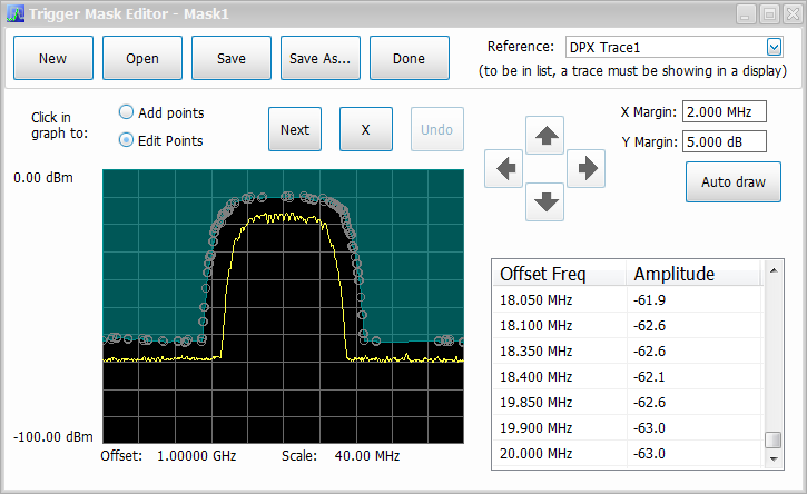
There are a couple ways to use the RSA to analyze the offending signal in our customer’s airfield radios. We can use a frequency mask trigger, where we define a spectral mask that generates a trigger if a signal crosses it. The RSA makes this easy to do with an Auto Draw option shown below which automatically creates a mask based on the currently displayed spectrum trace. If you have very specific requirements, you can also define the mask manually.

We can also use the DPX Density Trigger, which uses the colorized data from the DPX display to generate a trigger. As you can see, it’s as easy as finding the signal you want to trigger on, right clicking, and selecting “Trigger On This.”

Regardless of which trigger type is selected, the results are the same. We could immediately see how the spectral spreading manifests itself in the constellation diagram and the EVM vs Time displays. We observed that the previously tight constellation diagram is now very spread out with massive increases in EVM, large-scale phase rotations, significant amplitude and phase deviations around the decision points, and even symbols occurring at center of the diagram. The EVM vs Time display below shows us that there is a discrete section of the record affecting the signal’s overall quality. This also explained the intermittent failures reported by radio operators.


Next, we decided to open up two new displays to do further analysis. The Demod I&Q vs Time display above shows the baseband I and Q signals after removing the carrier. The RSA uses this data to populate the constellation diagram and calculate EVM. For this particular modulation type, the magenta dots indicating decision points should occur at the high and low levels of the waveforms. The EVM vs Time display shows the error vector magnitude value at each symbol. These values should all be very low, near 0%.
Stacking the Demod I&Q vs Time and EVM vs Time displays on top of each other, we could see that there are three starkly different sections of the signal. The beginning and end sections show a clean, correctly transmitted digital signal with reasonable decision points at the high and low voltage regions in the Demod I&Q vs Time display. The same leading and trailing sections in the EVM vs Time display show low error vector magnitude values consistent with a clean signal. It’s only in the middle that things look nasty. We then zoomed in to the beginning of the problematic section to see if we could learn anything more about the nature of the error.

Looking at the Demod I&Q vs Time display first, we could see that the magenta decision points to the left of the markers are all occurring at the high and low points of the IQ signals as they should be, but they’re all over the place to the right of the markers. For the most part, the I and Q signals are fairly smooth and continuous, but if you look directly to the left of M1 on the yellow I trace and MR on the blue trace, you can see a very sharp phase discontinuity in both signals. This also corresponds to the beginning of the poor EVM values and scattered decision points. After some more zooming in and panning around, we were able to determine that the signal had another phase shift 256 symbols later at the end of the distorted section. It turns out there was a phase shift of one quarter symbol period in the radio’s modulator that occurred once every 1.2 seconds. Our customer was very pleased with our findings and was able to take this information back to his team to resolve the problem with his radios. He also purchased an RSA and incorporated real-time analysis into his testing so that he could find these kinds of errors before releasing products in the future.
The RSA’s combination of high performance real-time spectrum analysis, powerful time-correlated triggering capabilities, and complete vector signal analysis allowed us to find and pinpoint the problematic signal and give our customer the information he needed to fix it. Case closed!