Introduction
This white paper describes the optically isolated measurement system architecture trademarked IsoVu™. IsoVu offers complete galvanic isolation and is the industry's first measurement solution capable of accurately resolving high bandwidth, low voltage differential signals in the presence of large common mode voltages. The stand out feature of IsoVu™ is its best in class common mode rejection across the entire bandwidth.
The target audience for this paper includes anyone making the following measurements:
- Differential measurements in the following conditions:
- Complete galvanic isolation is required
- High common mode voltage
- High frequency common mode interference
- Measurements in high EMI environments
- EMI compliance testing
- ESD testing
- Remote measurements up to 10 meters away from the device under test without loss in measurement performance
Measurement Pain Points and Sources of Error
Voltage is the difference of electrical potential between two points in a circuit, and any voltage measurement between two points is considered a differential voltage measurement. Even when using a passive probe with a ground clip it is considered differential because it's measuring the difference in potential between the probe tip and ground. However, the "ground" potential at the oscilloscope's input BNC connector is not necessarily the same as the "ground" in the circuit being measured. In other words, "ground is not ground".
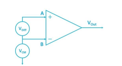
The objective of the differential measurement is to get a perfect representation of VA-B as shown in Figure 2. Unfortunately, the perfect representation of VA-B is not possible due to some of the following causes:
- Common mode voltage or common mode interference
- Radiated emissions
- Ground loops
- Measurement system inaccuracy
- Insufficient bandwidth
- Insufficient common mode rejection capability
- Insufficient sensitivity
The Common Mode Problem
Users making differential measurements with a traditional differential probe often fail to realize the trade offs and limitations when measuring in an environment where common mode voltage or common mode interference is present. The capabilities of today's differential probes derate over frequency for the following specifications:
- Common Mode Voltage (CMV)
- Common Mode Rejection Ratio (CMRR)
- Common Mode Loading
Voltage Derating over Frequency
All differential probes have a common mode voltage rating with some probes specifying a common mode voltage range of thousands of volts. However, the listed specification is generally true only at DC and low frequencies. The probe's common mode voltage capability is derated as the frequency of the signal increases, which severely limits the common mode voltage capability at higher frequencies.
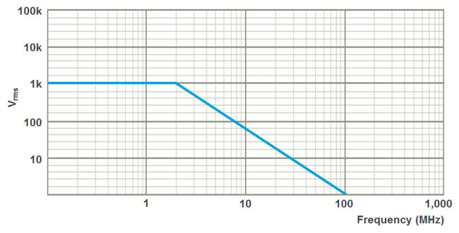
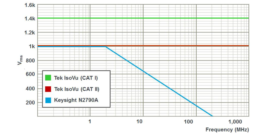
An example of this derating is the common mode voltage plot of Keysight's N2890A 100 MHz high voltage differential probe shown in Figure 3. Although the voltage rating of the probe is 1 kVrms at low frequencies, the probe's capabilities start to roll off at 2 MHz and this probe is only capable of 20 Vrms at 100 MHz. This is a limitation that is rarely understood and users often fail to realize that a probe such as this one with a 1 kVrms rating is only capable of 20 Vrms at maximum bandwidth. This misunderstanding can result in measurement inaccuracy and damaged equipment.
CMRR Derating over Frequency
Common-mode rejection ratio (CMRR) is a differential probe's ability to reject any signal that is common to both test points in a differential measurement (VA – VB). CMRR is a key figure of merit for differential probes and amplifiers, and it is defined by:
CMRR = | ADiff / ACM |
where:
ADiff = the voltage gain for the difference signal
ACM = the voltage gain for common-mode signal
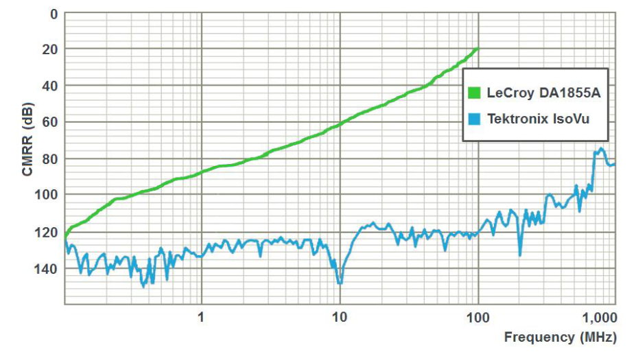
Ideally, ADiff should be large and ACM would be zero, resulting in an infinite CMRR. In practice, a CMRR of at least -80 dB (10,000:1) is considered quite good. An amplifier that has long been considered best in class is the LeCroy DA1855A. In Figure 4, the DA1855A's CMRR exceeds the -80 dB level at low frequencies up to a few MHz. However, the CMRR capability of this amplifier quickly derates and is only capable of a mere -20 dB or 10:1 at 100 MHz. What this means is that a common-mode input signal of 10 volts at 100 MHz will induce a 1 V error signal in the differential measurement. It should be noted that the plot in Figure 4 is for the amplifier only. When using "matched" probes with the amplifier the performance is further degraded.
Common Mode Loading Derating over Frequency
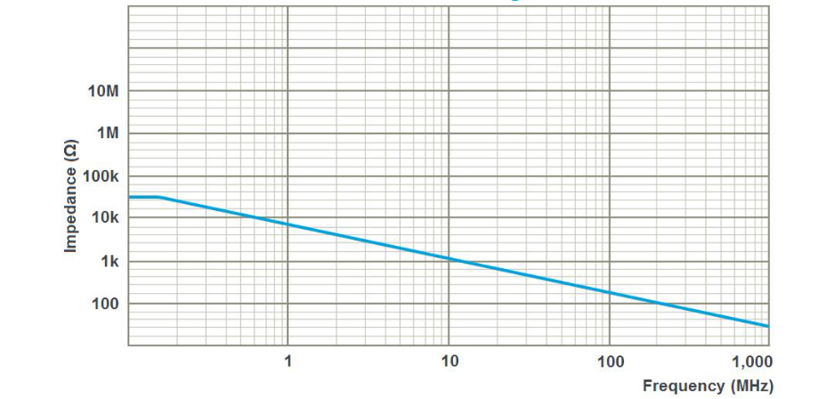
Although the common mode DC input impedance of a typical probe can be very high, as the signal frequency increases the common mode impedance is dominated by the common mode capacitance to ground. At higher frequencies, the capacitive loading becomes a matter of increasing concern by distorting the waveform and increasing the load on the DUT. As shown in Figure 5, the Keysight N2819A probe has a large common mode input impedance at DC and low frequencies but the impedance drops to 40 Ohms at 1 GHz.
Users need to pay careful attention to all three of these factors which can have a negative impact on the measurement results. The ideal measurement system would not have these limitations and deratings described above.
The IsoVu Solution to the Common Mode Problem
IsoVu Common Mode Voltage
IsoVu architecture with galvanic isolation provides common mode withstand voltages of > 2000 Vpeak across its frequency range with NO derating. The electrical limitation for an optically isolated solution such as IsoVu is many thousands of volts given IsoVu's 3 meter and 10 meter fiber optic lengths. Because IsoVu achieves galvanic isolation through its fiber optic connection, the only limitation in its common mode voltage rating is due to safety certification standards. Where the Keysight N2790A plot shows degraded performance over frequency, IsoVu has no derating over frequency.
IsoVu CMRR
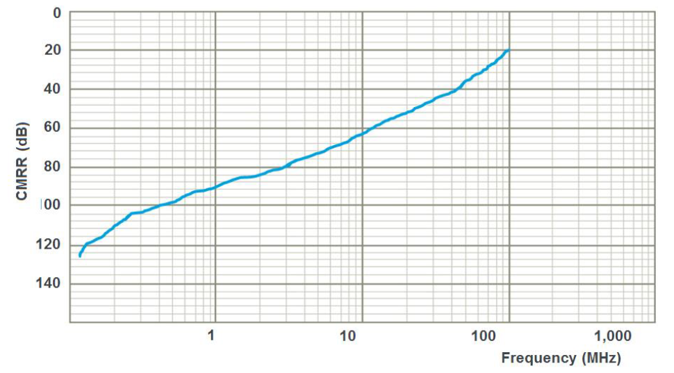
IsoVu achieves exceptional CMRR over the entire operating range due to the combination of complete galvanic isolation and its IsoVu sensor head architecture. It should be noted that the data in Figure 7 is representative of the actual measured CMRR because the measurement was limited by the sensitivity of the test system and the noise floor of the VNA. For comparison, the LeCroy DA1855A without probes at 100 MHz has a CMRR value of 20 dB (10:1) while IsoVu offers 120 dB (1 Million:1).
IsoVu Common Mode Loading
Since the IsoVu system has no electrical connection from the sensor head to ground or the rest of the test system, the only common mode loading is the parasitic capacitance from the sensor head to the environment. For example, placing the sensor head 6" (15.25 cm) above a reference plane would result in ~2 pF of parasitic capacitance between the sensor head and the reference plane.
IsoVu Theory of Operation
IsoVu utilizes an electro-optic sensor to convert the input signal to optical modulation, which electrically isolates the device-under-test from the oscilloscope. IsoVu incorporates four separate lasers, an optical sensor, five optical fibers, and sophisticated feedback and control techniques. The sensor head, which connects to the test point, has complete electrical isolation and is powered over one of the optical fibers. Figure 8 shows the block diagram
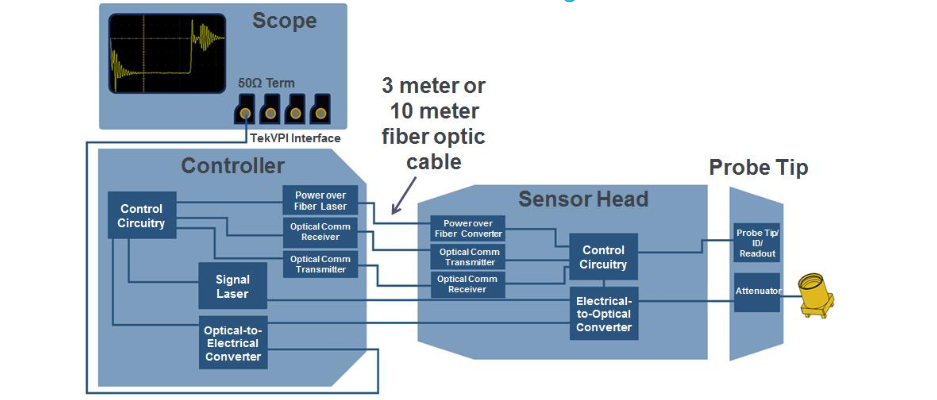
Controller
The Controller connects to the scope via a coax cable and TekVPI Comp Box. The Controller is powered directly from the TekVPI Interface. The Controller Box provides the following functions:
- TekVPI Interface communication/power link with host oscilloscope
- Microcontroller and support circuitry
- Power Over Fiber laser/driver
- Signal Laser, signal laser driver (adjustable output power) and thermo-electric cooler driver
- Optical Communication (RX/TX)
- Transimpedance Amplifier (TIA) and supporting circuitry
Sensor Head
The Sensor Head contains an electrical-to-optical sensor that converts the electrical signal from the DUT to an optical signal to be sent to the controller via the optical fiber link. The Sensor Head also contains a DC/LF feedback loop that measures the DUT signal and sends it to the controller for analysis. This allows the system to correct for a variety of drifts and offset errors in the system. The Sensor Head is powered by an optical link.
Tip Cables
The Tip Cables connect the DUT to the sensor head. A variety of Tip Cables with different attenuations will be provided and the customer will select which attenuation to use based on the signal being measured. The Tip Cable will connect to the Sensor Head via an SMA connector. Each tip cable will include readout encoding that allows the Sensor Head to communicate the attenuation factor to the scope to display the correct vertical scale factor.
Five different tip cables will be available with attenuation ranges from 1X to 50X and corresponding differential ranges from ± 1V to ± 50V. Since the sensor head input is a 50 Ohm SMA connector, users can connect directly to the sensor head with an SMA cable with a differential range of ± 1V. This input structure affords users the opportunity to build custom interfaces to the DUTs.
IsoVu Connectivity Options
Traditional high voltage differential solutions ship with robust accessories such as alligator clips or hook clips that have been suitable for higher voltage environments but have the trade-off of lower signal fidelity With increasing power densities and higher performance requirements, traditional accessories have become less useful. IsoVu offers multiple connectivity options to maximize both performance and convenience.
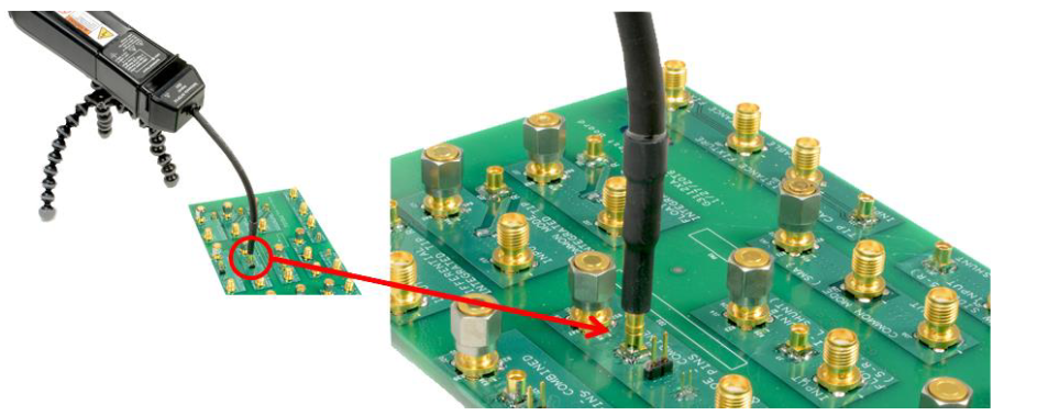
A reference design that can accommodate an MMCX connector as a test point will get the greatest performance and convenience using the IsoVu solution. With an MMCX connector at the end of the tip cable, IsoVu will easily snap into MMCX connectors on a reference design board as shown in Figure 10.
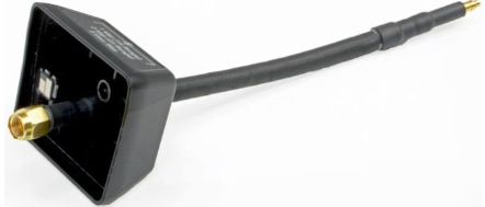
With a reference design that cannot accommodate an MMCX connector, the IsoVu measurement solution includes square pin adapters which will fit over square pins soldered onto the test board
IsoVu Banner Specifications
- Resolve <50V high speed differential voltages in the presence of large common mode voltages (up to 2 kVpeak)
- Bandwidth from DC to 1GHz
- Unmatched Common-Mode Rejection
- 120 dB (1 Million to 1) from DC - 100 MHz
- 80 dB (10,000 to 1) at 1 GHz
- Galvanically isolated measurement system architecture
- 3 m and 10 m separation between sensor head and controller for remote measurements and to reduce susceptibility of test equipment from DUT
- Resolve a 10 mV signal in 1X mode with a 1X tip and down to 5 mV using high res mode or averaging
Additional IsoVu Features
Output Clamping
IsoVu offers a unique selectable output clamping feature. When enabled, this feature will limit the output voltage swing of the IsoVu measurement system into the scope's input and will allow the user to increase the vertical sensitivity on the scope without the oscilloscope being overdriven or saturating. Overdriving the oscilloscope is a common user trap which results in the waveform being distorted or rolled off.
Input Referred Offset
Input referred offset extends the effective dynamic range of the measurement system by allowing the user to offset the DC component of their signal.
Long Cable Option
IsoVu will ship with either a 3 meter or 10 meter fiber optic cable solution between the sensor head and the controller allowing the user to remotely locate the device under test from the test system. Both cable options meet the full set of specifications.
Conclusion
Accurate differential measurements rely on a measurement system's bandwidth, rise time, common mode voltage, common mode rejection capability, and the ability to connect to smaller test points to characterize devices that are shrinking in size and increasing in performance. Despite these requirements, advancements in test and measurement for power testing, EMI testing, ESD testing, and remote measurement capability have been minimal at best and have not kept pace with changing requirements. While differential voltage probes have had modest performance gains in regard to bandwidth, these probes have failed to make any substantial improvements in regard to common mode rejection, and connectivity. IsoVu is a leap forward in technology and is the only solution with the required combination of high bandwidth, high common mode voltage, and high common mode rejection to enable these differential measurements.
Find more valuable resources at TEK.COM
Copyright © Tektronix. All rights reserved. Tektronix products are covered by U.S. and foreign patents, issued and pending. Information in this publication supersedes that in all previously published material. Specification and price change privileges reserved. TEKTRONIX and TEK are registered trademarks of Tektronix, Inc. All other trade names referenced are the service marks, trademarks or registered trademarks of their respective companies.
03/16 51W-60485-0