Свяжитесь с нами
Живой чат с представителями Tektronix. С 9:00 до 17:00 CET
Позвоните нам
С 9:00 до 17:00 CET
Загрузить
Загрузить руководства, технические описания, программное обеспечение и т. д.:
Обратная связь

Точные и воспроизводимые измерения PCIe
На протяжении почти двух десятилетий технология PCI Express® является широко используемым стандартом для высокоскоростных соединений последовательных интерфейсов. Новейшие спецификации PCIe® ориентированы на рынки с интенсивным использованием данных, такие как искусственный интеллект/машинное обучение и высокопроизводительные вычисления.
Наши решения для автоматизированного тестирования PCIe значительно упрощают тестирование за счет простых и понятных функций настройки и калибровки. В сочетании с оборудованием для измерений с низким уровнем шума эти решения обеспечивают быстрые, точные и воспроизводимые измерения. Будучи активным членом рабочих групп организации PCI-SIG® с правом голоса, мы обладаем опытом, необходимым для проверки передатчиков, приемников, генераторов опорной тактовой частоты и систем фазовой синхронизации (PLL).
PCI Express, PCIE и PCI-SIG являются зарегистрированными торговыми марками и/или знаками обслуживания PCI-SIG.
Комплексные решения для автоматизированного тестирования PCI Express
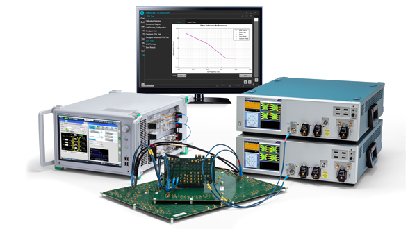
Ведущие в отрасли решения для тестирования передатчиков и приемников PCIe Base 6.0
Недавно выпущенная спецификация PCIe 6.0 Base отличается удвоенной полосой пропускания и энергоэффективностью. В PCIe 6.0 представлены такие функции, как многоуровневые сигналы PAM4 и прямое исправление световых ошибок (FEC) для поддержки высокой скорости передачи данных (64.0 GT/s) и сохранения малой временной задержки. Решение для тестирования передатчиков PCIe 6.0 от Tektronix позволяет инженерам решать современные проблемы проектирования и проверки. Интуитивно понятные инструменты, готовые к работе сразу после распаковки, поддерживают измерения напряжения и временных параметров, таких как отношение сигнала к сумме шума и искажений (SNDR) и измерения некоррелированного джиттера, обязательные в соответствии с последним требованием.
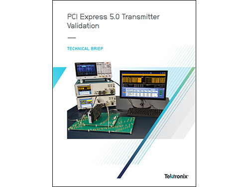
Решения для тестирования передатчиков PCIe Gen1 – Gen5
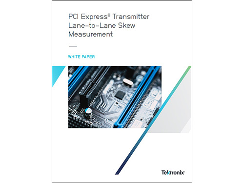
Наши решения для тестирования передатчиков PCIe поддерживают совместимость с предыдущими стандартами за счет решений для проверки и тестирования соответствия передатчиков PCIe от 2,5 до 32,0 GT/s (Gen1 – Gen5). Поддержка охватывает широкий диапазон от раннего определения характеристик напряжения/временных характеристик кремния до измерений передатчиков и опорных тактовых генераторов на уровне платформы. Технологические лидеры Tektronix обеспечивают актуальность этих решений благодаря тому, что включают все уведомления о технических изменениях (ECN) и поддерживают семинары по соответствию стандарту PCI-SIG в качестве одобренного решения.
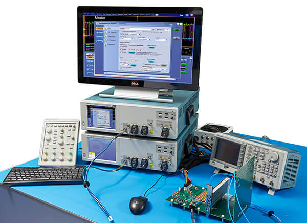
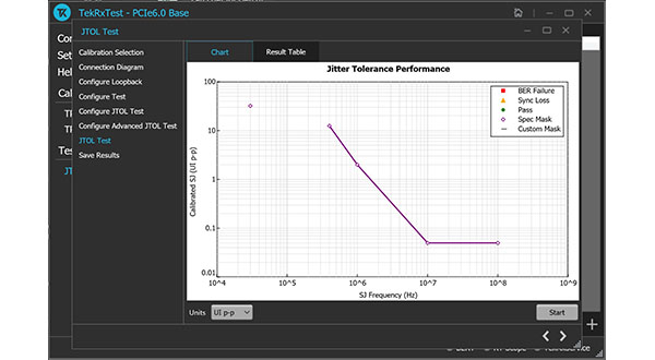
Решения для тестирования приемников PCIe и PLL
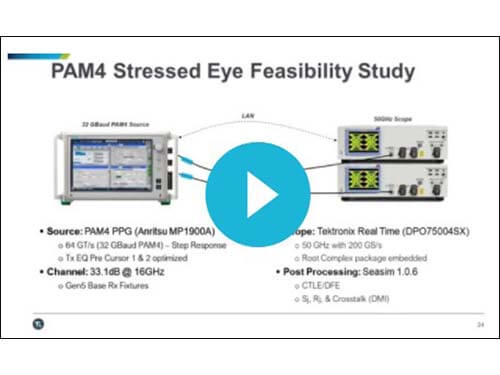
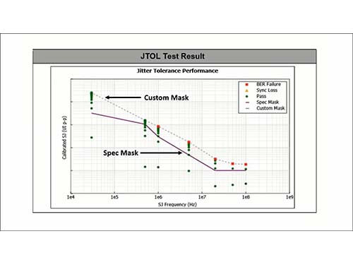
Проверка приемника PCIe отличается своей сложностью из-за чувствительности к калибровке глазковых диаграмм при стресс-тестах по каналу с высокой потерей. Решения Tektronix для тестирования приемников PCIe гарантируют, что ваша конструкция будет тщательно протестирована при требуемом коэффициенте битовых ошибок (BER). Наши интуитивно понятные инструменты содержат пошаговые инструкции для подготовки канала анализатора Anritsu BERT MP1900A для точного тестирования приемника. Автоматическое тестирование поддерживает калибровку глазковых диаграмм при стресс-тестах, новейшие тестирования на соответствие коррекции каналов передатчика и приемника, пользовательские запуски BER и определение границ допусков джиттера. Данное решение также позволяет легко проводить измерения полосы пропускания PLL передатчика и пиков.
Compute Express Link (CXL)
Архитектуры центров обработки данных должны постоянно отвечать требованиям к перемещению и доступу к данным, при этом сводя к минимуму энергопотребление, повышая эффективность и поддерживая более крупные и разнообразные приложения. Опираясь на преимущества физического уровня PCIe, CXL отвечает этим требованиям, позволяя процессорам эффективно обращаться к одним и тем же ресурсам памяти, взаимодействовать друг с другом и работать на единой архитектуре. Решения физического уровня от Tektronix поддерживают самую высокую скорость передачи данных CXL (32 GT/s) и различные форм-факторы, ожидаемые от этой новой технологии.