Introduction
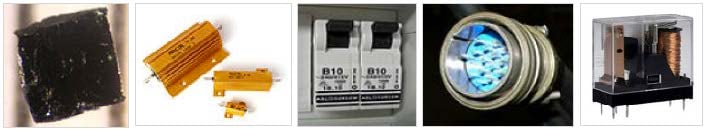
Low resistance measurements offer a good way to identify resistance elements that have changed over time. Often, these types of measurements are used to evaluate if a device or material has degraded due to environmental factors like heat, fatigue, corrosion, vibration, etc. For many applications, these measurements are typically lower than 10Ω. A change in resistance value is often the best indicator of some form of degradation between two points of contact. Low resistance measurements performed using high currents are commonly used to evaluate high power resistors, circuit breakers, switches, bus bars, cables and connectors, and other resistance elements.
Most digital multimeters (DMMs) lack the ability to make low resistance measurements with high currents. A DMM combined with a power supply will work, but these instruments must first be integrated into a system in order to automate the measurement process, then the resistance must be calculated manually.
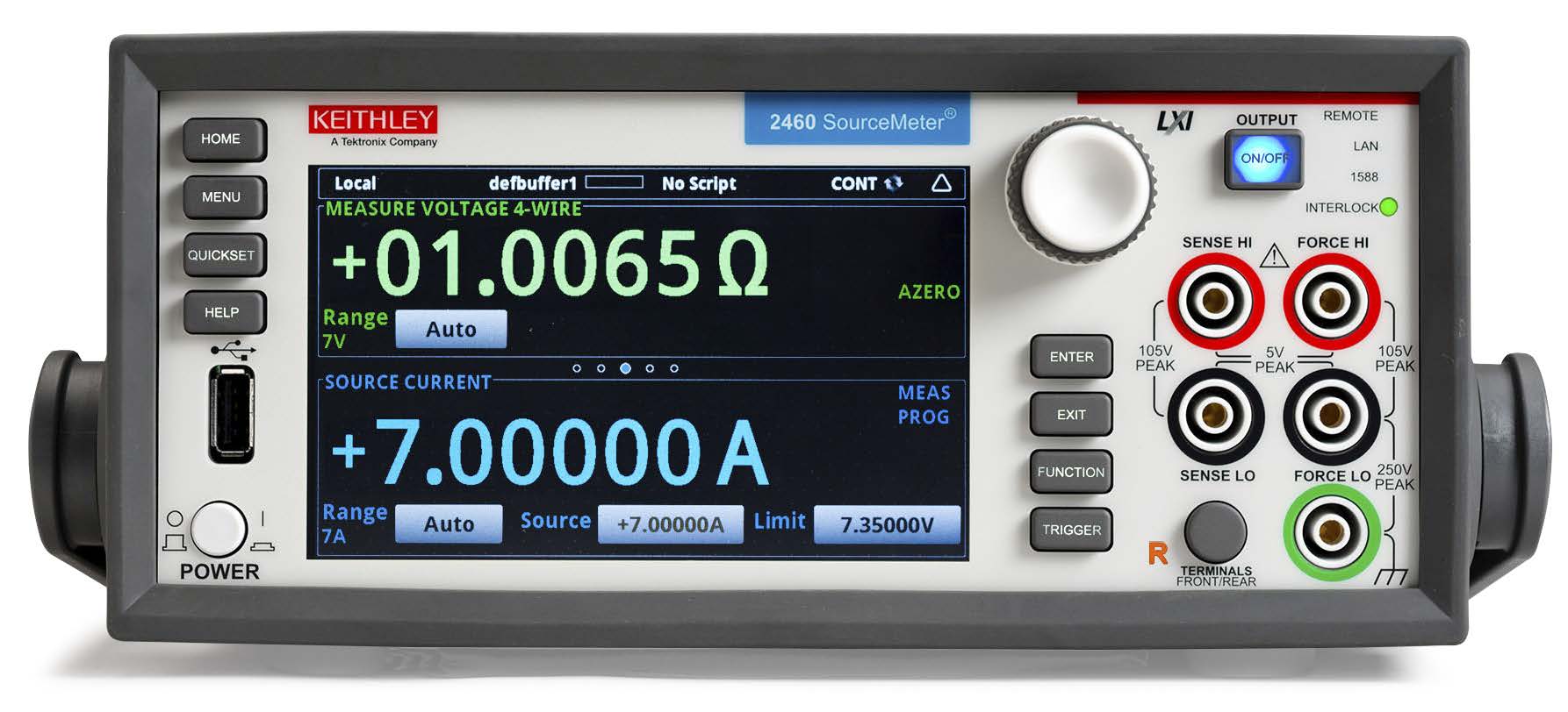
Source Measure Unit (SMU) instruments or SourceMeter® instruments can simplify making low resistance measurements with high current stimulus. A SourceMeter instrument is capable of sourcing and measuring both current and voltage. Keithley’s Model 2460 High Current SourceMeter SMU Instrument has the flexibility to source/sink high current and measure voltage and current, making it a perfect solution for measuring low resistance devices that require stimulus currents up to 7A. The Model 2460 automatically calculates the resistance, so there’s no need to make the calculation manually. Built-in features such as remote sensing and offset compensation help optimize low resistance measurements. The Model 2460 offers <1mΩ resolution.
Low resistance measurements can be made using either the Model 2460’s front-panel or rear-panel terminals, as shown in Figures 1 and 2. Note that either the front-panel terminals or rear-panel terminals must be used—the connections can’t be mixed.
When the leads are connected to the device under test (DUT), note that the FORCE LO and SENSE LO connections are attached to one of the DUT leads and the FORCE HI and SENSE HI connections are attached to the other lead. The sense connections should be connected as close to the resistor under test as possible. This four-wire measurement cancels out the resistance of the test leads in the measurement.
Figure 1 illustrates the front-panel connections, which can be made with four insulated banana cables that are rated to the maximum current (7A), such as two sets of Keithley’s Model 8608 High-Performance Clip Lead Set.
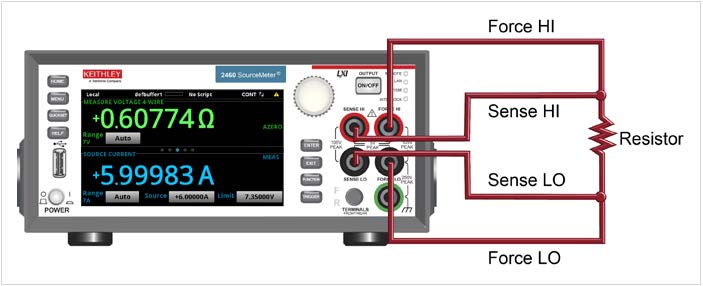
Figure 1. Model 2460 front-panel connections for low resistance measurements
Figure 2 illustrates the rear-panel connections, which can be made with either the Model 2460-KIT ScrewTerminal Connector Kit (included with the Model 2460) or a Model 2460-BAN Banana Test Leads/Adapter Cable with appropriate cabling.
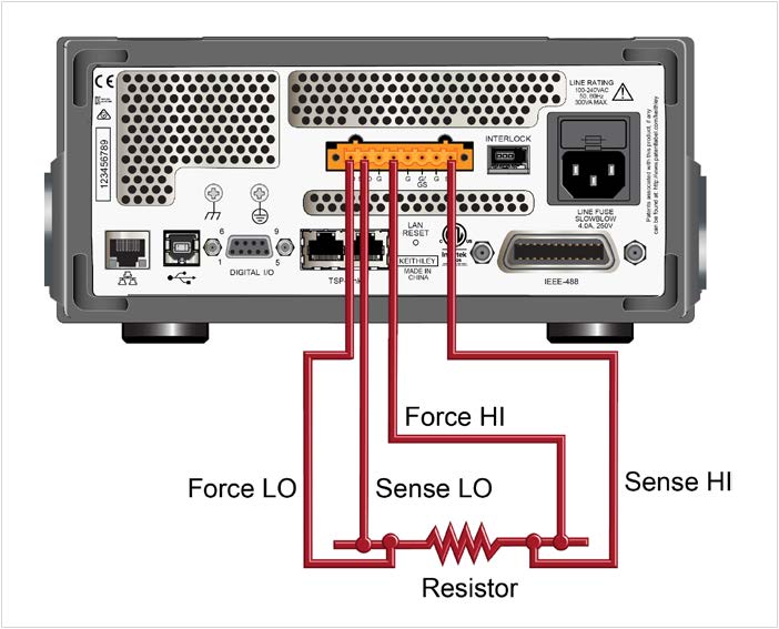
Figure 2. Model 2460 low resistance connections on rear panel
Common Sources of Error for Low Resistance Measurements
Low resistance measurements are subject to errors from a variety of sources, including lead resistance, non-ohmic contacts, and device heating.
Lead Resistance
As shown in Figure 3, all test leads have some level of resistance, some as high as hundreds of milliohms. This can result in an incorrect measurement if the lead resistance is high enough.
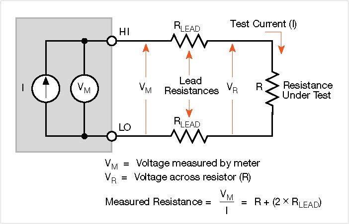
Figure 3. Two-wire resistance measurement with a SMU instrument
Thermoelectric Voltages
Thermoelectric EMFs or voltages are generated when different parts of a circuit are at different temperatures and when conductors made of dissimilar materials are joined together. A few microvolts can be generated by temperature gradients in the test circuit caused by fluctuating temperatures in the lab or a draft near the sensitive circuitry.
Non-Ohmic Contacts
Non-ohmic contacts are evident when the potential difference across the contact isn’t linearly proportional to the current flowing through it. Non-ohmic contacts may occur in a low voltage circuit as a result of oxide films or other nonlinear connections. To prevent non-ohmic contacts, choose an appropriate contact material, such as indium or gold. Make sure the SMU instrument’s compliance/limit voltage is high enough to avoid problems due to source contact non-linearity. To reduce error due to voltmeter non-ohmic contacts, use shielding and appropriate grounding to reduce AC pickup. (Refer to the latest edition of Keithley’s Low Level Measurement Handbook for further information on non-ohmic contacts.)
Device Heating
The test currents used for low resistance measurements are often much higher than the currents used for high resistance measurements, so power dissipation in the device can be a consideration if it is high enough to cause the device’s resistance value to change. Power dissipation in a resistor is given by the formula:
P = I2R.
From this relationship, we can see that the power dissipated in the device increases by a factor of four each time the current doubles. Therefore, one way to minimize the effects of device heating is to use the lowest current possible while still maintaining the desired voltage across the DUT. If the current level cannot be reduced, consider using a narrow current pulse rather than a DC signal.
How to Make Low Resistance, High Current Measurements Successfully
Lead Resistance and the Four-wire (Kelvin) Method
Resistance measurements are often made using the twowire method shown in Figure 3. The test current is forced through the test leads and the resistance (R) being measured. The meter then measures the voltage across the resistance through the same set of test leads and computes the resistance value accordingly.
The main problem with using the two-wire method for low resistance measurements is that the total lead resistance (RLEAD) is added to the measurement. Given that the test current (I) causes a small but significant voltage drop across the lead resistances, the voltage (VM) measured by the meter won’t be exactly the same as the voltage (VR) directly across the test resistance (R), resulting in considerable error. Typical lead resistances range from 1mΩ to 10mΩ, so it’s very difficult to obtain accurate two-wire resistance measurements when the resistance under test is lower than 10Ω to 100Ω (depending on lead resistance).
Due to the limitations of the two-wire method, the four-wire (Kelvin) connection method shown in Figure 4 is generally preferred for low resistance measurements. With this configuration, the test current (I) is forced through the test resistance (R) through one set of test leads, while the voltage (VM) across the DUT is measured through a second set of leads called sense leads. Although some small current may flow through the sense leads, it is usually negligible and can generally be ignored for all practical purposes. The voltage drop across the sense leads is negligible, so the voltage measured by the meter (VM) is essentially the same as the voltage (VR) across the resistance (R). Consequently, the resistance value can be determined much more accurately than with the two-wire method. Note that the voltage-sensing leads should be connected as close to the resistance under test as possible to avoid including the resistance of the test leads in the measurement.
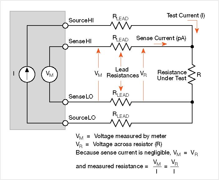
Figure 4. Four-wire resistance measurement with a SMU instrument
Thermoelectric Voltages (EMFs) and Offset-Compensated Ohms Method
The offset-compensated ohms method is a technique used to minimize thermoelectric EMFs. As shown in Figure 5a, the source current is applied to the resistance being measured during only part of the cycle. When the source current is on, the total voltage measured by the instrument (Figure 5b) includes the voltage drop across the resistor as well as any thermoelectric EMFs. During the second half of the measurement cycle, the source current is set to zero amps and the only voltage measured by the meter (Figure 5c) is any thermoelectric EMF present in the circuit. Given that VEMF is accurately measured during the second half of the cycle, it can be subtracted from the voltage measurement made during the first half of the cycle, so the offset-compensated voltage measurement becomes:
VM = VM1 – VM2
VM = (VEMF + IR) – VEMF
VM = IR and,
R = VM / I
Again, note that the measurement process cancels the thermoelectric EMF term (VEMF).
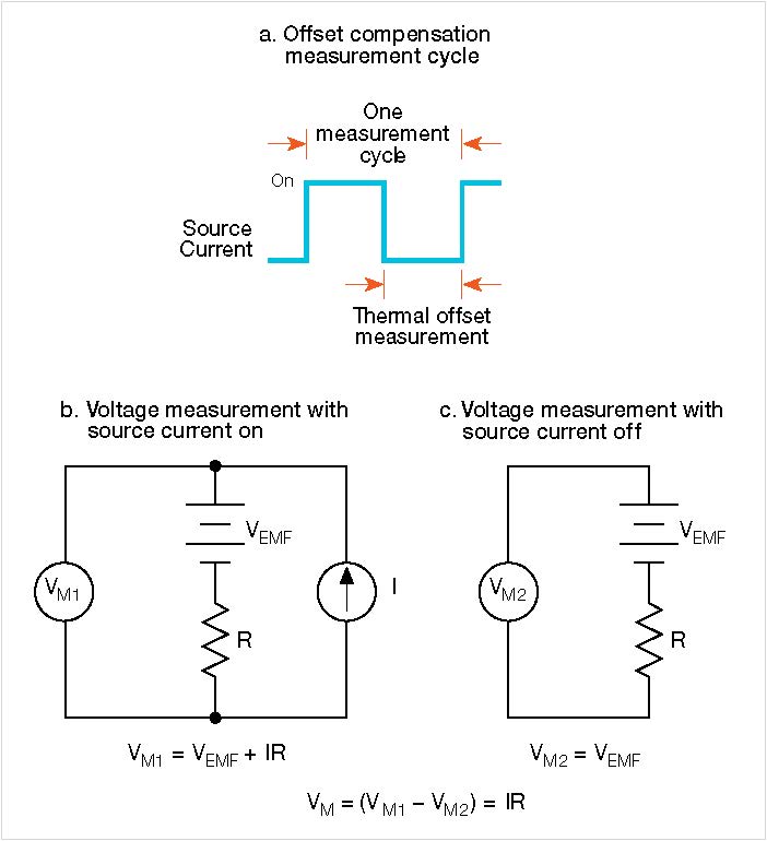
Figure 5. Offset-compensated ohms method
Instrument Limitations
Even hardware like SMU instruments that can supply DC currents as high as 7A has limits on the total amount of power it can output, which can impact the resistance value that can be measured. This limit is a function of the inherent equipment design and is typically dependent on design parameters, such as the maximum output of the power supply internal to the instrument itself, the safe operating area (SOA) of the discrete components used in the instrument, the spacing of the metal lines on the instrument’s internal printed circuit board, etc. Some of these design parameters are constrained by maximum current limits, some by maximum voltage limits, and some by maximum power limits (I×V).
Figure 6 shows the Model 2460’s maximum DC current and power at various operating points. For example, the maximum current in the SMU power envelope is 7A (point A in the figure) and a maximum voltage of 100V (point D). The maximum power the SMU can output is 100W, which is achieved at point D (1A×100V). At point A, the power is lower at 49W.
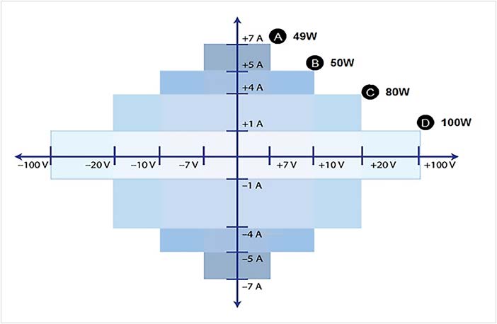
Figure 6. Model 2460 high current SMU instrument power envelope
Measuring Low Resistance Devices with the 2460 SourceMeter Instrument’s High Current Capability
Low resistance measurements can be made from the front panel or over the remote interface using SCPI code or TSP code. This involves these steps:
• Reset the instrument.
• Select the source current and measure resistance function.
• Set the current source value.
• Select four-wire (remote sense) mode. This eliminates the effect of lead resistance on measurement accuracy.
• Enable offset compensation. This reduces offsets caused by thermoelectric voltages.
• Turn on the source output and start making measurements.
• Generate readings from the front panel or the remote interface.
• Turn the source output off.
Set up the measurement from the front panel To set up the application from the front panel:
Make connections from the Model 2460 to the device under test.
1. Reset the instrument:
a. Press the MENU key.
b. Under System, select Manage.
c. Select System Reset.
d. Select OK.
2. Press the FUNCTION key.
3. Under Source Current and Measure, select Resistance.
4. Press the HOME key.
5. In the SOURCE CURRENT area, select the button next to Source. Select the source value.
6. Press the MENU key. Under Measure, select Settings.
7. For Sense Mode, select 4-Wire Sense.
8. Next to Offset Comp, select On.
9. Press the HOME key.
10. Press the OUTPUT ON/OFF switch to enable the output and start making measurements.
11. Press the OUTPUT ON/OFF switch to disable the output and stop making measurements.
The instrument displays the measurements in the MEASURE VOLTAGE area of the Home screen.
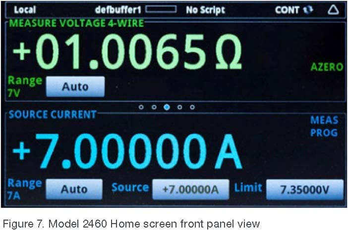
Figure 7. Model 2460 Home screen front panel view
View the measurements on the front panel, TREND swipe screen, and full GRAPH screen.
Both the resistance measurement result and the current being sourced can be viewed via the front panel.
Resistance measurements can be viewed as a function of time on the TREND swipe screen. To access this screen, swipe the bottom part of the Home screen to the right. A graph similar to the one in Figure 8 will appear.
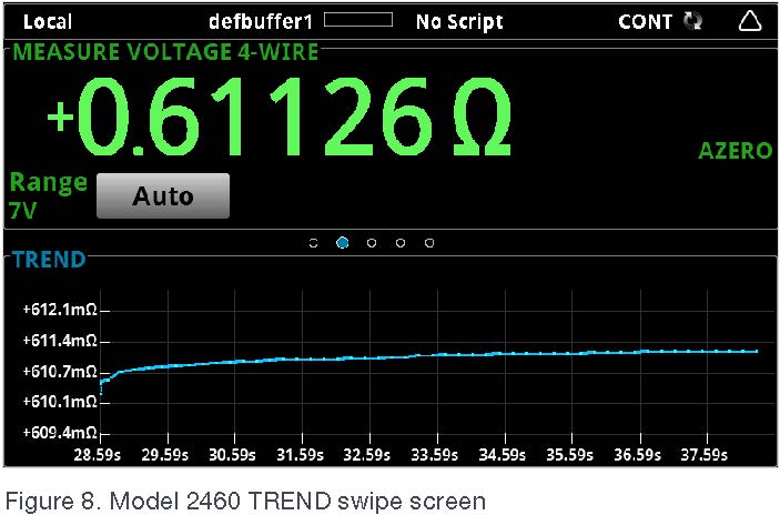
Figure 8. Model 2460 TREND swipe screen
To see the graph on the full screen, swipe up on the TREND swipe screen to open the Graph screen.
View the buffer statistics on the front panel.
The Model 2460 front-panel STATISTICS swipe screen displays a variety of measurement statistics, including:
• Buffer name
• Minimum, maximum, and average reading values
• Standard deviation
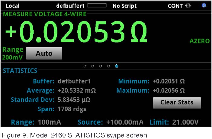
Figure 9. Model 2460 STATISTICS swipe screen
Set up the low resistance application using SCPI commands.
The following sequence of SCPI commands makes 100 low resistance measurements by sourcing current and measuring resistance. In this example, the source current magnitude and limit voltage are set automatically. Remote commands are used to change the front-panel display to display the TREND swipe screen, which allows viewing numeric data at the top of the screen and graphic data at the bottom of the screen.
Some changes may be required for this code to run in a specific programming environment. Send the following commands for this example application:
|
Command |
Description |
|
*RST |
Reset the Model 2460. |
|
TRIG:LOAD:LOOP:SIMP 100 |
Configure Simple Loop trigger model template to make 100 readings. |
|
SENS:FUNC “RES” |
Set to measure resistance. |
|
SENS:RES:RANG:AUTO ON |
Turn on auto range. |
|
SENS:RES:OCOM ON |
Enable offset compensation. |
|
SENS:RES:RSEN ON |
Set to use 4-wire sense mode. |
|
DISP:SCR PLOT |
Show the TREND swipe screen. |
|
OUTP ON |
Turn on the output. |
|
INIT |
Initiate readings. |
|
*WAI |
Wait until finished. |
|
TRAC:DATA? 1, 100, “defbuffer1”, READ, REL |
Read the resistance and time values from defbuffer1. |
|
OUTP OFF |
Turn off the output. |
Set up the low resistance application using TSP commands.
The following TSP code is designed to run from Keithley’s Test Script Builder (TSB). TSB is a software tool available via Keithley Instruments’ website. Once installed, TSB can be used to write code and develop scripts for TSP-enabled instruments. Information on how to use this tool is available in TSB’s online help file and in the “Introduction to TSP operation” section of the Model 2460 Reference Manual.
To use other programming environments, it may be necessary to modify the example TSP code. By default, the Model 2460 is configured to use the SCPI command set. Always select the TSP command set before sending TSP commands to the instrument.
To enable TSP commands:
1.Press the MENU key.
2.Under System, select Settings.
3.For Command Set, select TSP.
4.At the prompt to reboot, select Yes.
This sequence of TSP commands makes 100 low resistance measurements by sourcing current and measuring resistance. In this example, the source current magnitude and limit voltage are set automatically. It uses remote commands to change the front-panel display to the TREND swipe screen. This allows viewing numerical data at the top of the screen and graphical data at the bottom of the screen. After the code executes, the data is displayed in the Instrument Console of Test Script Builder.
Send the following commands for this example application:
|
--Reset the instrument to the default settings reset() --Configure the Simple Loop trigger model template to make 100 readings. trigger.model.load("SimpleLoop", 100) --Change the view on the front panel to the TREND swipe screen. display.changescreen(display.SCREEN_ PLOT_SWIPE) --Set to measure resistance, use 4-wire sense, --and offset compensation. smu.measure.func = smu.FUNC_RESISTANCE smu.measure.sense = smu.SENSE_4WIRE smu.measure.offsetcompensation = smu.ON --Turn on the output smu.source.output = smu.ON --Initiate trigger model and wait until finished. trigger.model.initiate() waitcomplete() --Turn off output smu.source.output = smu.OFF --Read the resistance and time values from defbuffer1. print("Resistance:\tTime:") for i = 1, 100 do print(string.format("%f\t%f", defbuffer1[i], defbuffer1.relativetimestamps[i])) end |
Conclusion
The Model 2460 SourceMeter SMU Instrument is an ideal tool for characterizing high current, low resistance devices and components because of its four-quadrant design, high power output, and ability to measure both current and voltage accurately. Using a single instrument to perform such tests simplifies test setup, reduces programming time, and saves rack space.