Current Language
×
Russian (Russia)

Выберите язык:

Включить меню
Current Language
×
Russian (Russia)

Выберите язык:

Загрузить

Загрузить руководства, технические описания, программное обеспечение и т. д.:

ТИП ЗАГРУЗКИ
МОДЕЛЬ ИЛИ КЛЮЧЕВОЕ СЛОВО

Обратная связь

Fast PCIe Rx Insight Using the TMT4 Margin Tester


Introduction

Traditional receiver equalization testing is performed using a calibrated oscilloscope and Bit Error Rate Tester (BERT)

setup to test the performance of the device under test’s (DUT) receiver (Rx). While the scope and BERT setup provides a very accurate and precise method of testing a receiver, there are

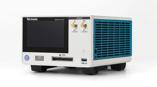
a few drawbacks to these systems, namely, calibration times, which can be several hours for a single test point, cost, and the expertise required to proficiently set up and run the tests. Tektronix has introduced a new tool to the PCIe testing toolkit, the TMT4 Margin Tester, which is intended to complement these scope and BERT systems by addressing the big pain points associated with scope and BERT testing.

  • Easy and simple setup – ready to test in under 10 minutes
  • Rapid Rx testing – x16 lane Rx results in 1 minute
  • Cost effective – compared to the cost of a scope and BERT system

Since the TMT4 Margin Tester’s Rx test is fundamentally different from the scope and BERT, the logical question is: “how do the results of TMT4 Margin Tester’s Rx test relate to traditional compliance system results?”. This application note discusses the TMT4 Margin Tester’s Rx test, highlights the differences between the test methodologies of TMT4 Margin Tester and compliance test setups, and reviews an experiment comparing the results of TMT4 Margin Tester’s Rx test to results from a compliance test.


Receiver Link Equalization Testing

The PCIe CEM standard is a high-speed serial computer expansion bus standard that is maintained and developed by the PCI Special Interest Group (PCI-SIG®). One of the primary goals of the PCIe standard is to enable interoperability between PCIe devices. The specification provides the test

list that all vendors designing add-in cards (AIC), or system boards must comply with. One of the primary tests, and arguably the most difficult to pass, is the Receiver Link Equalization (Rx LEQ) test.

The Rx LEQ test verifies that the system will correctly negotiate with its link partner to adjust the partner’s transmitter equalization appropriately and verifies that there is no more than one-bit error per 10E12 bits transmitted is

identified with a stressed signal. The test includes two primary parts: stressed eye calibration and the Rx LEQ test itself.

The PCIe Gen 4 stressed eye calibration is a 47-step process where an oscilloscope is used to dial in the BERT settings for amplitude, pre-shoot, de-emphasis, Random Jitter (RJ),

Sinusoidal Jitter (SJ), Insertion Loss, Differential Mode Noise (DMI), Common Mode Noise (CMI), Eye Width and Eye height. This can be a difficult task to perform manually for even an experienced operator and with automated test software

this process can still take several hours and is not always guaranteed to converge on a correctly stressed test signal.

Once the stressed eye calibration is complete, the AIC or system board can be connected to the BERT to perform the Rx LEQ test. The DUT and BERT will first undergo the auto-negotiation step, and the DUT will pick its preferred preset, or coefficients, for the BERT Tx. The BERT will transmit the calibrated stressed eye to the DUT Rx, and the DUT will transmit the received bits back to the BERT’s error detector. As noted previously, in order to pass the DUT must not transmit more than one bit-error for every 10E12 bits transmitted.

AIC TP2 Calibration

Figure 1: AIC TP2 Calibration Setup


AIC Rx LEQ Setup

Figure 2: AIC Rx LEQ Setup


TMT4 Margin Tester Rx Test

The TMT4 Margin Tester uses a fundamentally different approach to receiver testing as compared to a BERT. At its most basic level, the TMT4 Margin Tester is stepping down its transmitter’s amplitude while maintaining the trained preset’s equalization. Additionally, the TMT4 Margin Tester’s

internal electronics, cable, and adapter cards aim to use most of the loss budget allowed by the PCIe Gen 4 specification which introduces stress by further attenuating the signal and creating inter-symbol-interference (ISI). To fully understand what the TMT4 Margin Tester is changing during the Rx test, the fundamentals of PCIe equalization must be understood.

The PCIe Gen 4 specification utilizes a 3-tap Finite Impulse Response (FIR) filter for equalization on the Tx side where three consecutive pulses are multiplied with their respective coefficients and added to generate the filter output. The

coefficients C–1, C0, and C+1 are called precursor, main cursor, and postcursor and are required to satisfy the rules below which are defined in the PCIe spec. Here, LF and FS stand for Low Frequency and Full Swing. Every TMT4 Margin Tester has a LF of 14 and a FS of 40.

a. |C–1| <= Floor (FS/4)
b. |C–1| + C0 + |C+1| = FS
c. C0 – |C–1| – |C+1| >= LF
PCIe Gen4 Base Spec Section 4.3.1.4


The PCIe specification uses transmit de-emphasis to compensate for high-frequency channel loss and defines these targets in the specification (see Figure 3). The specification defines eleven standard presets by their C–1 and C1 ratios, along with their target pre-shoot and de-emphasis, which all PCIe transmitters must support. Figure 4 represents the resultant output signal when a binary input stream is applied to the 3-tap FIR filter with the associated emphasis applied. De-emphasis (Va) is a boost that appears

Tx Preset Ratios and Corresponding Coefficient Values
Figure 3: Tx Preset Ratios and Corresponding Coefficient Values


just after the polarity inversion. Flat Level (Vb) is a constant voltage that will appear when bits of the same polarity are being transmitted. Pre-Shoot (Vc) is a boost that appears just before the polarity inversion. Maximum Boost (Vd) is a major boost appears when there is polarity inversion only for one-bit interval. Vd represents the full-swing voltage.

Definition of Tx Voltage Levels and Equalization Ratios
Figure 4: Definition of Tx Voltage Levels and Equalization Ratios


Now that we have the basics of PCIe equalization covered, we can outline the structure of the TMT4 Margin Tester’s Rx test. To begin, the TMT4 Margin Tester and the DUT will go through the link training process, where the DUT will select the optimal preset. The TMT4 Margin Tester has pre-defined test tables for each preset; Figures 5 and 6 are the test ranges for presets 1 and 6. The first line represents the typical cursor values for the associated preset, along with the calculated full-swing voltage, pre-shoot, and de-emphasis. Next, the TMT4 Margin Tester will incrementally decrease the full swing, dropping the signal amplitude while maintaining the emphasis targets defined for that preset. The attenuated eye height along with the ISI introduced by the adapter and cable creates a functional stressed eye test to help margin a DUT’s RX performance. The next part of the paper will cover how the TMT4 Margin Tester Rx test compares to traditional Rx testing and how its Rx tests results can be interpreted.

Preset 1 Rx Test Table
Figure 5: Preset 1 Rx Test Table


Preset 8 Rx Test Table
Figure 6: Preset 8 Rx Test Table


Comparing TMT4 Margin Tester Results with Traditional Compliance Testing

To test the correlation between the TMT4 Margin Tester and the traditional compliance test, four commercially

available AIC DUTs of varying performance were chosen for comparison. The test procedure was as follows:

  1. Each DUT was tested ten times on Lane 0 (L0) by a TMT4 Margin Tester. If there was a failure indicated, the main cursor value, C0, was recorded.
  2. Calibrated stressed eye for TP1. See calibration details below.
  3. Calibrated stressed eye for TP2 AIC. See calibration details below.
  4. Each AIC DUT was tested ten times at TP2. BER measurement was run for five minutes to get 95% confidence for BER of 1E-12.

Rx Comparison: DUT #1


The four AIC DUT’s were evaluated in order of best case to worst case from a compliance test perspective. In the case of the first DUT, the TMT4 Margin Tester Rx test showed all passing results, which correlates well with the results from the compliance test, and the DUT trained consistently to P5 in both scenarios. This DUT would very likely get a passing result at a compliance workshop.


The second DUT showed mixed results in the compliance testing but showed all passing results in the TMT4 Margin Tester Rx test and trained to the same presets for all tests. While there is a mix of pass and fail results in the compliance test, the DUT was never failed to complete the test, and in each case ended with fewer than 50 bit errors in 10E12 bits. Though there are five failures in ten tests, the bit errors are low enough on the failures that a failing result could be rerun to achieve passing results at a workshop. Despite the TMT4 Margin Tester indicating all passes even with mixed pass/ fail results in the compliance test, the result still indicates a likelihood of passing compliance at a workshop.


DUT 3 failed on all TMT4 Margin Tester runs and trained to P5 20% and P9 80% of the time. This inconsistency was matched by the compliance test where the DUT seemingly chose the BERTs preset randomly between P5, P6, and P9. DUT 3 passed only 30% of the compliance tests and frequently had sync loss or clock loss issues that brought down the link and made it unrecoverable without a hard reset of the DUT. This DUT could pass at a compliance workshop, but that is a very low probability outcome.


DUT 4 failed on all but one of the TMT4 Margin Tester runs and trained to P5 70% and P9 30% of the time. This inconsistency was matched by the compliance test where the DUT seemingly chose the BERTs preset randomly between P5 and P6, but interestingly never trained to P9. Ninety percent of the compliance tests could not be completed due to sync loss or clock loss issues which caused the link to fail. It is highly unlikely that this DUT would pass at a compliance workshop.

Although the sample size of this experiment is small, two key learnings can be found on how to estimate receiver margin when testing with the TMT4 Margin Tester. The first learning is comparing the BERT C0 to the TMT4 Margin Tester C0 test result. If the TMT4 Margin Tester C0 fail is greater than the BERT’s C0 value, the DUT has little receiver margin and is likely to struggle with the compliance test. If the TMT4 Margin Tester C0 fail is less than the BERT C0, the DUT has a higher margin and a higher chance of passing the compliance test. This can be seen in the experiment comparing the TMT4 Margin Tester C0 fail for DUT 3 and DUT 4 to the BERT C0.

The second learning is the stability of link training over repeated TMT4 Margin Tester tests. DUT 1 and 2 demonstrated a high level of consistency by training to the same preset every run. This stability carried over to the compliance test which resulted in easy compliance passes. DUT 3 and 4 had an exceptionally low consistency during link training and this instability carried over to compliance testing resulting in fails in certain cases.

Note: If sync loss or clock loss was seen during the test, the BER test was re-run with the stress disabled to check if errors were caused on the back channel. None of the DUTs tested above had issues with back-channel bit errors so sync loss or clock loss is attributed to the failure of the DUT Rx.

Conclusion

During this experiment, there was a functional pass/fail correlation between results from the TMT4 Margin Tester and compliance testing across these four devices. While this conclusion may not always apply to every DUT, it is an encouraging result given the differences in the two testing methodologies. The TMT4 Margin Tester can be used to provide insight into board receivers and provides test results in under a minute for sixteen lanes devices. Using a BERT together with a TMT4 Margin Tester enables engineers to gather a truly holistic view of the receiver performance of their PCIe Gen 3 and Gen 4 devices.