
A New Software Deskew Approach Accelerates Double Pulse Testing
Accurate energy loss measurements are one of the key objectives of double pulse testing. Eliminating the timing skew between voltage and current probes is a critical step in making accurate power and energy measurements on an oscilloscope.
The double pulse testing software (WBG-DPT), available on the 4B Series, 5B Series and 6B Series MSOs, includes a new deskew technology designed specifically for double pulse testing. This novel approach is very different from the traditional approach and significantly faster. It can shave hours off of testing.
The technique works for power converters that use either FETs or IGBTs. For the purpose of this post, we will use FET terminology to keep things simple.
Why Deskew?
Energy loss during switching must be minimized in the design of any power converter. This energy loss can be measured using an oscilloscope. The general approach is to multiply concurrent voltage and current samples to generate a power waveform.
p(t) = v(t)*i(t)
Since the power waveform represents energy consumption over time, energy can be determined by integrating the power waveform:
E = ∫p(t)dt
For these energy loss measurements to be accurate, the transitions of current and voltage waveforms should align in time. So, in order to achieve meaningful energy loss measurements, designers must correct for different delays introduced by test fixtures and probes.
Traditionally, the skew between probes is computed before starting any measurement on the test setup. For low-voltage applications, a function generator and deskew adapter (Tektronix P/N 067-1686-03) can be used for alignment. However, this approach is not optimal for high-voltage and high-current applications.
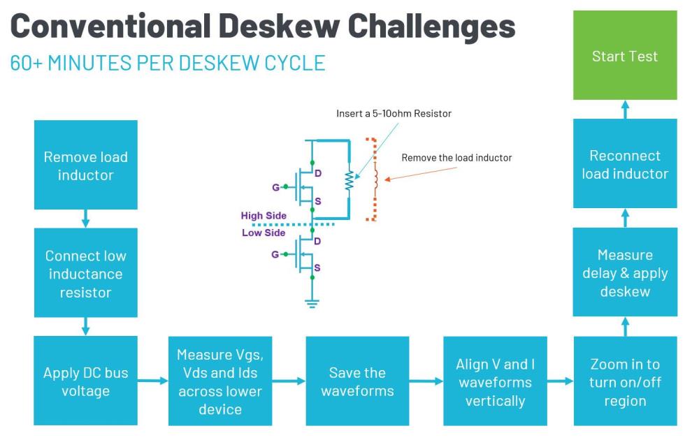
The traditional technique for aligning higher power, low side drain-to-source- voltage (VDS) and drain current (ID) measurements requires rewiring the test setup. The load inductor must be removed and replaced with a resistor. Then measurements are made and the VDS and ID measurements are aligned. This procedure can take an hour or more.
A New Deskew Approach
The Tektronix WBG-DPT solution’s industry-first software based deskew technique eliminates the need for rewiring and is performed after double pulse measurements have been taken. In the new method, the drain current (ID) is acquired and used as a reference waveform. During turn-on, a low-side VDS alignment waveform is calculated using a parametric model of the test circuit. The alignment waveform references the ID waveform and will have zero skew with respect to ID. The deskew algorithm determines the skew between the calculated VDS alignment waveform and the measured VDS waveform. It then applies the skew correction to the VDS measurement channel.
The Deskew Procedure
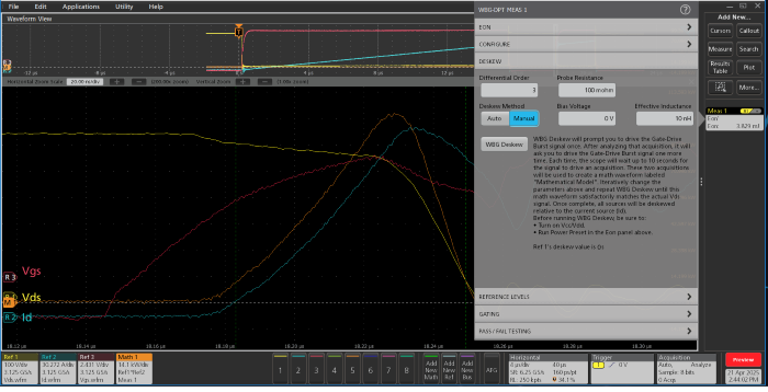
As noted above, the deskew can be performed after the measurements are taken. One can start a double pulse test without worrying about skew between VDS and ID, later select the Deskew settings and provide the following parameters:
- Probe resistance - assumed to be a current viewing resistor (CVR) or shunt resistor in this post
- Effective “loop” inductance
- Bias Voltage (the mean VDS across the low-side FET when it is off)
- Differential Order (filter order used by the model for smoothing)
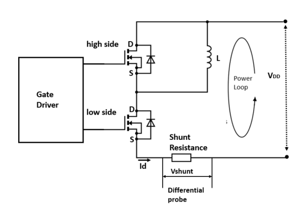
Figure 3. The equivalent circuit used to build the VDS_low alignment waveform. This circuit assumes a current viewing resistor is being used to measure ID.
Bias Voltage and Effective Inductance values can be determined automatically. The parameters entered in the deskew menu are used to build the VDS alignment waveform. The waveform is built using Kirchhoff’s Voltage Law:
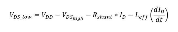
Where:
VDD - VDS_high represents the power rail voltage and drop across the high-side FET. Note that during turn-on, this will be constant since VDD is fixed and VDS_high is the voltage across the high-side FET’s body diode.
Rshunt is the resistance of the current shunt.
ID is the measured drain current, based on the drop across Rshunt.
dID/dt is the measured rate of change of drain current.
Leff is the effective inductance of the entire power loop.
During turn-on, VDD-VDS_high will be practically constant as noted above. Rshunt and Leff are also constant. This means the modelled VDS_low alignment waveform is a function of ID.
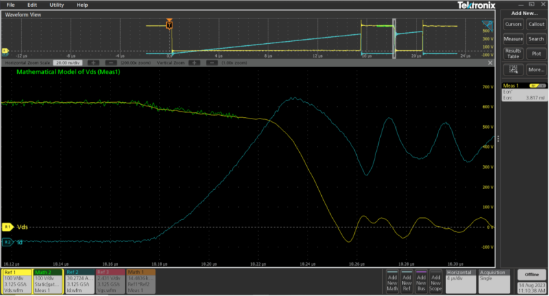
After configuring the parameters, the user presses the WBG deskew button. The system generates a mathematical model of VDS, based on the specified parameters and the drain current. This alignment waveform is displayed on the screen.

Figure 4. The VDS alignment waveform, calculated from ID, is compared to the measured
VDS waveform. Skew is the time difference between the alignment and measured waveforms. Once
calculated, the skew can be removed from the ID waveform.
The effective inductance, Leff, is a “lumped” element that considers the entire loop as shown above. Thus, Leff often unknown and getting it dialed in will be an iterative process. The deskew process can easily be run repeatedly, and adjustments can be made to Leff, until the calculated alignment waveform and the measured VDS waveform have the same shape. If there are differences in the shapes of the modeled VDS alignment waveform and the measured VDS waveform, the parameters can be adjusted and the deskew can be run again.
Once the parameters accurately represent the system, the modeled alignment waveform will have the same shape and the system can determine and correct the skew. The skew value shows up in the Deskew settings and is automatically applied to the channel to which the VDS signal is connected.
This new process accurately accounts for skew and reduces the deskew time from an hour or more to just 5 to 10 minutes.
With WBG-DPT software, circuit parameters like effective inductance and bias voltage can be determined automatically. As a result, skew value can be computed with less manual intervention.
To learn more about double pulse testing, visit the Double Pulse Testing web page.