By Tom Ohlsen
There are several sources of inaccuracy when testing laser diodes, which are at the heart of 3D sensing devices. In this installment of our blog series on 3D sensing and laser diode testing I will explore a number of these challenges including coupling high current pulses to the DUT, optical detector coupling, and slow response and inaccuracy in the detector itself. We’ll also discuss ways to handle these problems and achieve shorter test times, more accurate results, and lower reject rates using a Keithley source-measure unit.
The main test of a laser diode is a Light-Current-Voltage (LIV) curve that simultaneously measures a device’s electrical and optical output power characteristics, ideally early in the process to sort laser diodes or weed out bad devices. In a LIV test, the device under test (DUT) is hit with a current sweep as the forward voltage drop is recorded along with optical power.
For several reasons, this test is best done in a pulsed fashion early in production, before the laser diode is assembled into a module. For diodes still on the wafer (VCSELs, for example) or in a bar (edge emitting lasers), pulse testing is essential because, at that point, the devices have no temperature control circuitry. Testing with DC would, at the very least, change their characteristics; at worst, it would destroy them. Later on, in production, when they've been assembled into modules with temperature controls, the devices can be DC tested and the results compared to the pulse test. In addition, some devices will pass a DC test and fail a pulsed test.
The LIV test data is analyzed to determine laser characteristics, including lasing threshold current, quantum efficiency, and the presence of "kinks" (non-linearities) in the output as shown below.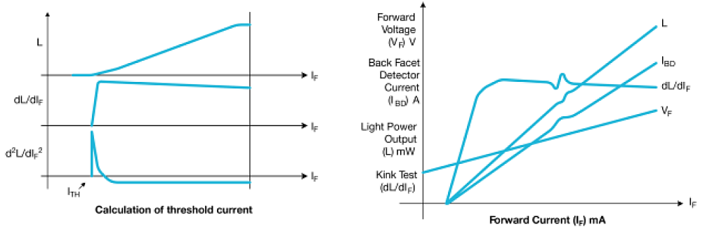
Pulse shape
Testing a laser diode properly requires a current pulse of the right shape. It should reach full current fairly quickly (but not so fast that it causes overshoot and ringing), then stay flat long enough to ensure that the result accurately represents the laser diode's true output. For early stage testing. it's common to use pulse widths of 500ns to 1µs, with a duty cycle of about 0.1%. Currents can range from a few tens of milliamps to 5A. This can put great demands on the system, especially with respect to impedance matching.
Impedance matching to the laser diode
Given that it's necessary to deliver a high speed current pulse to the laser diode and avoid problems with reflections, intuition would indicate using a transmission-line structure— probably a piece of coaxial cable. But the most familiar type of coaxial cable has 5Ω impedance, and the diode's impedance is closer to 2Ω—a terrible mismatch. Although it would be possible to put a 48Ω resistor in series, that brings on its own problems: pushing 5A through a 50Ω system takes a generator output of 250V, which can be dangerous to both people and equipment. In addition, the laser's dynamic resistance decreases with current, so the characteristics of the test setup change over the course of the test.
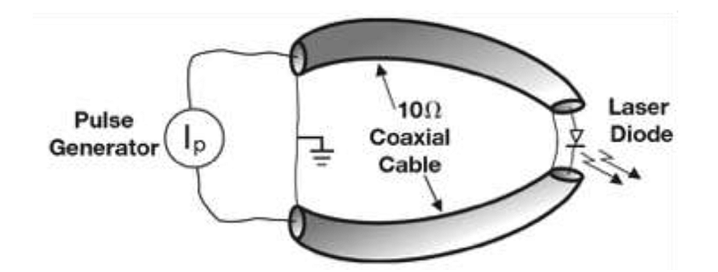
The use of low impedance coax is one possible approach, but that has its own problems related to changing dynamic resistance in the laser diode. There's another alternative: make the laser diode electrically part of the center conductor of a 10Ω line and feed the whole thing with a pulsed current source as illustrated below. This way, it takes less than 10V to push 5A through the diode. And because the system has a current source, we avoid problems with changing dynamic resistance in the laser diode.
Even the most careful impedance matching is not perfect, however, so it's good practice to keep all transmission lines short to minimize the effect of reflections and ringing.
Another reason to keep the connections short is to minimize the area (and hence, the inductance) of the loop formed at the connection to the laser diode. Remember that the voltage across an inductor is given by:
Reaching the desired slew rate of 5A/50ns requires 10V/nH. Unless the loop area is kept very small, the required voltage can easily exceed the compliance voltage of the instrument, dramatically extending the settling time.
Making electrical measurements
Measuring voltage and current in the laser diode fed with high speed pulses isn't easy. Even putting a scope probe on the diode to measure the voltage can cause problems. For one thing, where should the ground be connected? It may be necessary to float the scope or run it off batteries. The probe must be good to 1 GHz, but it's important to remember that the probe, regardless of its impedance, has a certain physical size, so it can act as an unshielded, unterminated transmission line stub with electrical characteristics that vary wildly with frequency.
Measuring current is a little more straightforward. A low value resistor (one with a value much lower than the resistance of the laser diode) connected in series will work, but it must have low capacitance and inductance. A wire wound resistor, which is basically a lossy inductor, is not suitable for high frequencies.
Choosing the optical detector
There are three common detector materials: silicon (Si), germanium (Ge), and indium gallium arsenide (InGaAs). Each has its advantages and disadvantages. As shown below, the choice of detector depends largely on the wavelength of light involved.
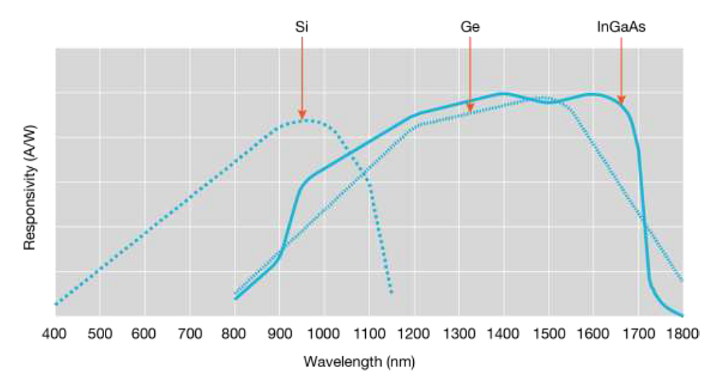
At wavelengths less than about 800nm, silicon is the only choice. But much telecommunications work is done between 1300nm and 1700nm, where it would appear that InGaAs would be best, because its response is fairly uniform, and it holds up well to about 1700nm. However, InGaAs has a problem with pulse response. It's desirable to test with a pulse short enough to avoid overheating the laser diode, yet long enough for it to reach some sort of steady state before the pulse is over. An InGaAs detector does not "settle," even within a 10 µs pulse. If the pulse width were decreased to 1µs, the problem would be even worse. Ge does not suffer from this effect, so it is preferable for short pulses. For this and other reasons, we recommend using a Ge detector for pulse measurements in conjunction with the Model 2520INT integrating sphere.
Coupling to the detector
There are several ways to couple the output from the laser diode to the detector. One is simply to put the laser right against the detector, but this method has several drawbacks. Not all the light may reach the detector. For example, if the laser's output beam is elliptical, the beam diameter is larger than the detector's active area, or the beam is not exactly centered on the detector, an unknown fraction of the light will be missed. In addition, some detectors are polarization-sensitive, which can cause further inaccuracy. On top of that, today's high-power laser diodes produce enough output to saturate many detectors.
Often, the best solution is an integrating sphere—a hollow ball coated on the inside with a diffuse reflecting material and equipped with a mounting for a detector and a port for feeding in the light to be measured as shown below. This is far from a new invention—Philadelphia Electric Co. used large integrating spheres mounted on trucks to test carbon-arc streetlights around 1915. The integrating sphere accepts all the light from the source, randomizes its polarization, and distributes it evenly over its inside surface. A detector mounted through the side of the sphere then "sees" a measurable and repeatable fraction (about 1%) of the light fed into the sphere. There's plenty of light to measure, but not enough to overpower the detector.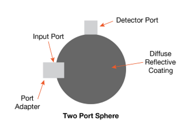
Test speed
There was a time when demand for fiberoptic telecommunications equipment exceeded supply, and manufacturing efficiencies were a secondary consideration. Today, efficiency and low cost are vital, and only the swift and productive will survive. Testing, like everything else, must be fast, accurate, and inexpensive. This means an optical power meter is a bad choice. This instrument integrates light output over time, and with a low duty cycle input that can be a long time indeed. On top of that, the accuracy of the measurement depends on how accurately the duty cycle of the pulses is known and how closely the duty cycle of the light output matches the duty cycle of the electrical input.
To get around this problem, the conventional way to test laser diodes, as shown below, involves a pulse source, optical measurement components (photodiode detectors, etc.), a pair of high speed voltage-to-current converters, and a high speed, multi-channel oscilloscope. The pulse source produces a pulse and the other instruments measure the electrical and optical responses, feeding the results via GPIB to a PC.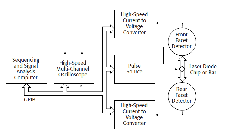
With this set up, the test process may take a few thousand pulses. Sometimes, there will be a few hundred pulses at each current level, with a boxcar averager integrating them. This would seem to improve sensitivity, resolution, and accuracy, but it can cover up problems with waveform distortion. It is also a lengthy process, taking anywhere from tens of seconds to several minutes per DUT. The system can do perhaps 2,500 parts per day and costs up to $150,000 per test stand. There must be a faster and cheaper way.
A faster, all-in-one system
Lasers used in fiber optic communication systems and optical data storage devices are sold in highly competitive markets, and a less expensive and faster way to test them makes a big difference to a manufacturer's bottom line.
Instead of the home-brew pulsed LIV testing set-up discussed above, a more efficient and simpler approach is a single instrument solution, namely the Keithley Model 2520 pulse laser diode test system. This instrument is essentially a pulsed source-measure unit with output impedance and cabling that closely matches the impedance of the laser diode. As shown below, the measurement portion of the system incorporates multi-channel data acquisition, dedicated timing circuitry, high speed current-to-voltage converters, and a digital signal processor (DSP) that emulates DSO functionality and controls much of the measurement sequence.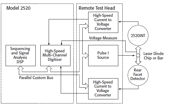
With this solution, the sequencing of the LIV sweep is orchestrated by an internal DSP that is programmed only once via the GPIB bus for a given test sequence. Once programmed, the DSP can execute complete pulsed LIV sweeps without interaction with other equipment or the control computer. In fact, the instrument provides control signals directly to the component handling system via a digital I/O port.
By having the DSP as an integral part of the digitizing channels, fast analysis of captured pulse measurements is made without the time-consuming analysis sequence described previously. This reduces a pulsed LIV test time to only a few seconds and greatly minimizes software complexity.
With individual test times of only a few seconds, up to 15,000 devices per day can be tested, even when assuming only 85% system utilization due to WIP flow irregularities, maintenance, etc. The new system costs just a fraction of the price of the older one and has higher throughput, so it's possible to cost justify purchasing additional make-up capacity to reduce production planning uncertainties.
One approach to designing this type of system is to include both pulsed and non-pulsed operating modes. This dual functionality allows both types of LIV sweeps to be performed on a single platform, using the same measurement channels. Comparing pulsed and non-pulsed test results provides more complete information on DUT performance. Also, the dual mode source can be located in a remote test head, which shortens the distance between the pulse source and the laser diode without the need to locate the instrument at the laser test station. The shorter cable length reduces measurement settling time and helps improve accuracy.
By incorporating all the relevant functions in one instrument, a third-generation LIV test system can greatly accelerate test throughput.