Свяжитесь с нами
Живой чат с представителями Tektronix. С 9:00 до 17:00 CET
Позвоните нам
С 9:00 до 17:00 CET
Загрузить
Загрузить руководства, технические описания, программное обеспечение и т. д.:
Обратная связь
TIVP Series IsoVu Measurement System User Manual
This manual describes installing and setting up the TIVP Series IsoVu Measurement System, and provides specifications and basic probe operations.
Это руководство относится к следующему:
TIVP02, TIVP05, TIVP1, TIVP02L, TIVP05L, TIVP1L
- Тип руководства: Основной потребитель
- Номер по каталогу: 071369207
- Дата выпуска:
- Revision: Rev B
By downloading, you agree to the terms and conditions of the Manuals Download Agreement.
Manuals Download Agreement
ATTENTION: please read the following terms and conditions carefully before downloading any documents from this website. By downloading manuals from Tektronix' website, you agree to the following terms and conditions:
Manuals for Products That Are Currently Supported:
Tektronix hereby grants permission and license to owners of Tektronix instruments to download and reproduce the manuals on this website for their own internal or personal use. Manuals for currently supported products may not be reproduced for distribution to others unless specifically authorized in writing by Tektronix, Inc.
A Tektronix manual may have been revised to reflect changes made to the product during its manufacturing life. Thus, different versions of a manual may exist for any given product. Care should be taken to ensure that one obtains the proper manual version for a specific product serial number.
Manuals for Products That Are No Longer Supported:
Tektronix cannot provide manuals for measurement products that are no longer eligible for long term support. Tektronix hereby grants permission and license for others to reproduce and distribute copies of any Tektronix measurement product manual, including user manuals, operator's manuals, service manuals, and the like, that (a) have a Tektronix Part Number and (b) are for a measurement product that is no longer supported by Tektronix.
A Tektronix manual may be revised to reflect changes made to the product during its manufacturing life. Thus, different versions of a manual may exist for any given product. Care should be taken to ensure that one obtains the proper manual version for a specific product serial number.
This permission and license does not apply to any manual or other publication that is still available from Tektronix, or to any manual or other publication for a video production product or a color printer product.
Disclaimer:
Tektronix does not warrant the accuracy or completeness of the information, text, graphics, schematics, parts lists, or other material contained within any measurement product manual or other publication that is not supplied by Tektronix or that is produced or distributed in accordance with the permission and license set forth above.
Tektronix may make changes to the content of this website or to its products at any time without notice.
Limitation of Liability:
TEKTRONIX SHALL NOT BE LIABLE FOR ANY DAMAGES WHATSOEVER (INCLUDING, WITHOUT LIMITATION, ANY CONSEQUENTIAL OR INCIDENTAL DAMAGES, DAMAGES FOR LOSS OF PROFITS, BUSINESS INTERRUPTION, OR FOR INFRINGEMENT OF INTELLECTUAL PROPERTY) ARISING OUT OF THE USE OF ANY MEASUREMENT PRODUCT MANUAL OR OTHER PUBLICATION PRODUCED OR DISTRIBUTED IN ACCORDANCE WITH THE PERMISSION AND LICENSE SET FORTH ABOVE.
Read Online
OPERATING INFORMATION
- Measurement system handling best practices
- Environmental requirements
- Clearance requirements
- Controls and indicators
- Cable flags
- Sensor tip cable
- Connecting to a circuit
- Self-calibration
- AutoZero
- Menu button
- Ranges
- Auto Range
- Selecting a sensor tip cable
- Deskew
- Input offset
- Input coupling AC or DC
- Voltage range
- Connecting the sensor tip cables
- Installing the probe tip adapters
- Installing the square pins on the circuit board
TEKTRONIX END USER LICENSE AGREEMENT
This End User Agreement (“Agreement”) is an agreement between Tektronix, Inc., an Oregon corporation, and its corporate affiliates, subsidiaries, and divisions as applicable (collectively, “Tektronix,” “we,” “us,” or “our”) and You (including any entity or organization you represent, collectively, “Customer” or “You”). Please read this Agreement carefully as this Agreement governs the terms and conditions under which You are permitted to use Tektronix’s software and services.
THE SOFTWARE, ENCODED OR INCORPORATED WITHIN EQUIPMENT OR ACCOMPANYING THIS AGREEMENT, IS FURNISHED SUBJECT TO THE TERMS AND CONDITIONS OF THIS AGREEMENT. BY INDICATING YOUR ACCEPTANCE OF THESE TERMS BY SELECTING AN "ACCEPT” OR SIMILAR BUTTON IN A SOFTWARE MENU, OR BY RETAINING THE SOFTWARE FOR MORE THAN THIRTY DAYS OR USING THE SOFTWARE IN ANY MANNER YOU (A) ACCEPT THIS AGREEMENT AND AGREE THAT YOU ARE LEGALLY BOUND BY ITS TERMS; AND (B) REPRESENT AND WARRANT THAT: (I) YOU ARE OF LEGAL AGE TO ENTER INTO A BINDING AGREEMENT; AND (II) IF YOU ARE A REPRESENTATIVE FOR A CORPORATION OR OTHER LEGAL ENTITY, YOU HAVE THE RIGHT, POWER, AND AUTHORITY TO ENTER INTO THIS AGREEMENT ON BEHALF OF SUCH ENTITY AND BIND SUCH ENTITY TO ITS TERMS. IF YOU DO NOT AGREE TO THE TERMS OF THIS AGREEMENT, TEKTRONIX WILL NOT AND DOES NOT LICENSE THE SOFTWARE TO YOU AND YOU MUST NOT DOWNLOAD, INSTALL, OR USE THE SOFTWARE. UNITED STATES GOVERNMENT CUSTOMERS OR END-USERS MAY REQUEST A GOVERNMENT ADDENDUM TO THIS AGREEMENT.
NOTWITHSTANDING ANYTHING TO THE CONTRARY IN THIS AGREEMENT OR YOUR ACCEPTANCE OF THE TERMS AND CONDITIONS OF THIS AGREEMENT, NO LICENSE IS GRANTED (WHETHER EXPRESSLY, BY IMPLICATION, OR OTHERWISE) UNDER THIS AGREEMENT TO ANY SOFTWARE THAT YOU DID NOT ACQUIRE LAWFULLY OR THAT IS NOT A LEGITIMATE, AUTHORIZED COPY OF TEKTRONIX’S SOFTWARE.THIS AGREEMENT EXPRESSLY EXCLUDES ANY RIGHTS CONCERNING SUCH ILLEGITIMATE COPIES.
IF THESE TERMS ARE NOT ACCEPTABLE, THE UNUSED SOFTWARE AND ANY ACCOMPANYING DOCUMENTATION SHOULD BE RETURNED PROMPTLY TO TEKTRONIX (WITHIN 30 DAYS OF PURCHASE) FOR A FULL REFUND OF THE LICENSE FEE PAID. (FOR INFORMATION REGARDING THE RETURN OF SOFTWARE ENCODED OR INCORPORATED WITHIN EQUIPMENT, CONTACT THE NEAREST TEKTRONIX SALES OFFICE.)
DEFINITIONS
“Equipment” means Tektronix equipment that the Software is encoded or incorporated within or installed onto.
LICENSE
Subject to the terms and conditions of this Agreement, Tektronix grants You a non-exclusive, non-transferable license to the Software, as follows
- Use the Software with the Equipment, or if the Software is not encoded or incorporated in any Tektronix equipment, on no more than one machine at a time; and
- Copy the Software for archival or backup purposes, provided that no more than one (1) such copy is permitted to exist at any one time, and provided that each copy includes a reproduction of any patent or copyright notice or restrictive rights legend that was included with the Software, as received from Tektronix;
- Fully transfer the Equipment to a third party but only if prominently accompanied by this End User License Agreement, and such third-party recipients agree to be bound by the terms of this Agreement; and
- Integrate Tektronix products that contain the Software into a system and sell or distribute that system to third parties, provided that those third parties are bound by the terms of this Agreement, and provided that You (i) do not separate the Software from any Equipment it is incorporated into, (ii) do not retain any copies of the Software, and (iii) do not modify the Software.
- Use the Software other than for its intended purpose as provided above in the section “You may,” or in conflict with the terms and restrictions of this Agreement;
- Distribute or transfer the Software to any person or organization outside of Your organization without Tektronix’s prior written consent, except in connection with a permitted use authorized in “You may” paragraphs 3 or 4 above;
- Decompile, decrypt, disassemble, or otherwise attempt to derive the source code, techniques, processes, algorithms, know-how, or other information (collectively “Reverse Engineer”) from the Software or permit or induce any third party to do so, except to the limited extent allowed by directly applicable law or third party license (if any), and only to obtain information necessary to achieve interoperability of independently created software with the Software;
- Modify, translate, adapt, or create derivative works of the Software, or merge the Software with any other software;
- Copy the documentation accompanying the Software;
- Remove any copyright, trademark, or other proprietary notices from the Software or any media relating thereto; or
- Export or re-export, directly or indirectly, the Software or Equipment, any associated documentation, or systems created in accordance with “You may” section 4 above, to any country to which such export or re-export is restricted by law or regulation of the United States or any foreign government having jurisdiction without the prior authorization, if required, of the Office of Export Administration, Department of Commerce, Washington, D.C. and the corresponding agency of such foreign government;
- Use the Software or Equipment in any manner or for any purpose that infringes, misappropriates, or otherwise violates any intellectual property rights or other proprietary rights of any person, or any applicable laws;
- Use the Software or Equipment in a network or system with other products or services that are incompatible, insecure or not compliant with applicable laws;
- Bypass, circumvent, damage or otherwise interfere with any security or other features of the Software or Equipment designed to control the manner in which they are used, or harvest or mine Tektronix’s proprietary content or information from the Software or Equipment.
THE SOFTWARE MAY NOT BE USED, COPIED, MODIFIED, MERGED, OR TRANSFERRED TO ANOTHER EXCEPT AS EXPRESSLY PERMITTED BY THESE TERMS AND CONDITIONS.
FEEDBACK
If You provide feedback to Tektronix concerning the functionality and performance of the Software or Equipment, including without limitation identifying potential errors and improvements, any comments, questions, suggestions, or the like ("Feedback"), Tektronix is free to use such Feedback without any attribution, compensation, or restriction in any manner to improve or enhance its products, irrespective of any other obligation or limitation between the Parties governing such Feedback. You hereby grant Tektronix an irrevocable, worldwide, perpetual, royalty-free license to use Your Feedback for any purpose whatsoever and waive any moral rights You may have in the Feedback. Tektronix is not obligated to use Your Feedback.
OWNERSHIP
Title to the Software and all copies thereof, but not the media on which the Software or copies may reside, shall remain with Tektronix or others from whom Tektronix has obtained a respective licensing right.
GOVERNMENT NOTICE
If the Software or any related documentation is acquired by or for an agency of the U.S. Government, the Software and documentation shall be considered “commercial computer software” or “commercial computer software documentation” respectively, as those terms are used in 48 CFR §12.212, 48 CFR §227.7202, or 48 CFR §252.227-7014, and are licensed with only those rights as are granted to all other licensees as set forth in this Agreement.
TERM
The license granted herein is effective until terminated. The license may be terminated by You at any time upon written notice to Tektronix. The license may be terminated by Tektronix if You fail to comply with any term or condition and such failure is not remedied within fifteen (15) days after notice hereof from Tektronix. Upon termination by either party, You shall return to Tektronix or destroy, the Software and all associated documentation, together with all copies in any form.
IF YOU TRANSFER, DISTRIBUTE, OR OTHERWISE MAKE AVAILABLE ANY COPY, MODIFICATION, OR MERGED PORTION OF THE SOFTWARE WITHOUT THE AS EXPRESS PERMISSION OF THESE TERMS AND CONDITIONS OR PRIOR WRITTEN CONSENT OF TEKTRONIX, YOUR LICENSE WILL BE IMMEDIATELY AND AUTOMATICALLY TERMINATED.
LIMITED WARRANTY
Tektronix does not warrant that the functions contained in the Software will meet Your requirements or that the operation of the Software will be uninterrupted, secure, or error-free.
EXCEPT AS SEPARATELY PROVIDED IN A WRITTEN WARRANTY FROM TEKTRONIX, THE SOFTWARE IS PROVIDED “AS IS” WITHOUT ANY WARRANTY OF ANY KIND, EXPRESS OR IMPLIED, INCLUDING BUT NOT LIMITED TO, THE WARRANTIES OF MERCHANTABILITY, FITNESS FOR A PARTICULAR PURPOSE, TITLE, QUIET ENJOYMENT, AND NON-INFRINGEMENT.
THE SOFTWARE IS NOT DESIGNED OR INTENDED FOR USE IN HAZARDOUS ENVIRONMENTS REQUIRING FAIL-SAFE PERFORMANCE INCLUDING WITHOUT LIMITATION, IN THE OPERATION OF NUCLEAR FACILITIES, AIRCRAFT NAVIGATION OR COMMUNICATION SYSTEMS, AIR TRAFFIC CONTROL, WEAPONS SYSTEMS, DIRECT LIFE-SUPPORT MACHINES, OR ANY OTHER APPLICATION IN WHICH THE FAILURE OF THE SOFTWARE COULD LEAD TO DEATH, PERSONAL INJURY OR SEVERE PHYSICAL OR PROPERTY DAMAGE (COLLECTIVELY "HAZARDOUS ACTIVITIES"). TEKTRONIX AND ITS AFFILIATES, LICENSORS, AND RESELLERS EXPRESSLY DISCLAIM ANY EXPRESS OR IMPLIED WARRANTY OF FITNESS FOR HAZARDOUS ACTIVITIES.
LIMITATION OF LIABILITY
IN NO EVENT SHALL TEKTRONIX, ITS AFFILIATES, LICENSORS, OR RESELLERS BE LIABLE FOR: (1) ECONOMICAL, INCIDENTAL, CONSEQUENTIAL, INDIRECT, SPECIAL, PUNITIVE OR EXEMPLARY DAMAGES, WHETHER CLAIMED UNDER CONTRACT, TORT OR ANY OTHER LEGAL THEORY, (2) LOSS OF OR DAMAGE TO YOUR DATA OR PROGRAMMING, LOSS OF PROFITS, BUSINESS INTERRUPTION, OR OTHER PECUNIARY LOSS ARISING FROM THE USE OF (OR INABILITY TO USE) THE SOFTWARE, (3) PENALTIES OR PENALTY CLAUSES OF ANY DESCRIPTION, (4) ANY DAMAGE, CLAIMS, OR LOSSES RESULTING FROM THE USE OF THE SOFTWARE IN CONJUNCTION WITH OTHER PRODUCTS OR SERVICES (INCLUDING THIRD-PARTY PRODUCTS OR SERVICES); OR (5) INDEMNIFICATION OF YOU OR OTHERS FOR COSTS, DAMAGES, OR EXPENSES RELATED TO THE GOODS OR SERVICES PROVIDED UNDER THIS LIMITED WARRANTY, EVEN IF TEKTRONIX OR ITS AFFILIATES, LICENSORS, OR RESELLERS HAVE ADVANCE NOTICE OF THE POSSIBILITY OF SUCH DAMAGES. BECAUSE SOME STATES/JURISDICTIONS DO NOT ALLOW THE EXCLUSION OR LIMITATION OF LIABILITY FOR CONSEQUENTIAL OR INCIDENTAL DAMAGES, SOME OF THE ABOVE LIMITATIONS MAY NOT APPLY TO YOU, BUT THEY SHALL APPLY TO THE MAXIMUM EXTENT PERMITTED BY LAW. NOTWITHSTANDING ANYTHING HEREIN TO THE CONTRARY, IN NO EVENT SHALL TEKTRONIX’S TOTAL AGGREGATED LIABILITY TO YOU FOR ALL DAMAGES IN ANY ONE OR MORE CAUSES OF ACTION EXCEED THE AMOUNT RECEIVED BY TEKTRONIX FROM YOU FOR THE SOFTWARE OR EQUIPMENT.
You are solely responsible for Your data. You must back up Your data before Tektronix or a third party performs any remedial, upgrade, or other work on Your systems, including any Equipment. If applicable law prohibits exclusion of liability for lost data, then Tektronix will only be liable for the cost of the typical effort to recover the lost data from Your last available back up.
SECURITY DISCLAIMER
This Software and its associated Equipment are not designed or intended to be used with unsecure networks. You acknowledge that use of the Equipment may rely upon certain networks, systems, and data communication mediums that are not controlled by Tektronix and that may be vulnerable to data or security breaches, including, without limitation, internet networks used by Your internet providers and the databases and servers controlled by Your internet providers. Tektronix shall not be liable for any such breaches, including without limitation, damages and/or loss of data related to any security breach, and disclaims all warranties, including any implied or express warranties that any content will be secure or not otherwise lost or altered.
For the avoidance of doubt, if You choose to connect this Software or Equipment to a network, it is Your sole responsibility to provide and continuously ensure a secure connection to that network. You agree to establish and maintain appropriate measures (e.g., firewalls, authentication measures, encryption, anti-virus applications, etc.) to protect the Software and Equipment and any associated data against security breaches including unauthorized access, destruction, use, modification, or disclosure.
Notwithstanding the foregoing, You shall not use any Products in a network with other products or services that are incompatible, insecure or not compliant with applicable laws.
THIRD-PARTY DISCLAIMER
The Software may contain software owned by third parties and obtained under a license from those parties (“Third Party Software”). Your use of such Third Party Software is subject to the terms and conditions of this Agreement and the applicable Third Party Software licenses. Except as expressly agreed otherwise, third parties do not warrant the Third Party Software, do not assume any liability with respect to its use, and do not undertake to furnish any support or information relating thereto.
GENERAL
Unless the Customer is the United States Government, this Agreement contains the entire agreement between the parties with respect to the use, reproduction, and transfer of the Software, and shall be governed by the laws of the state of Oregon.
You shall be responsible for any taxes that may now or hereafter be imposed, levied or assessed with respect to the possession or use of the Software or the rights and licenses granted under this Agreement, including any sales, use, property, value added, and excise taxes, and similar taxes, duties, or charges.
Any waiver by either party of any provision of this Agreement shall not constitute or be deemed a subsequent waiver of that or any other portion.
You may not assign this Agreement or any right or obligation under this Agreement, or delegate any performance, without Tektronix’s prior written consent. This section does not prohibit You from transferring the Equipment in accordance with Subsections 3 and 4 of the Section titled “You may” above.
All questions regarding this Agreement should be directed to the nearest Tektronix Sales Office.
Third Party Software Licenses
This component module is generated by Processor Expert. Do not modify it. Copyright : 1997 - 2015 Freescale Semiconductor, Inc. All Rights Reserved. THIS SOFTWARE IS PROVIDED BY THE COPYRIGHT HOLDERS AND CONTRIBUTORS "AS IS" AND ANY EXPRESS OR IMPLIED WARRANTIES, INCLUDING, BUT NOT LIMITED TO, THE IMPLIED WARRANTIES OF MERCHANTABILITY AND FITNESS FOR A PARTICULAR PURPOSE ARE DISCLAIMED. IN NO EVENT SHALL THE COPYRIGHT HOLDER OR CONTRIBUTORS BE LIABLE FOR ANY DIRECT, INDIRECT, INCIDENTAL, SPECIAL, EXEMPLARY, OR CONSEQUENTIAL DAMAGES (INCLUDING, BUT NOT LIMITED TO, PROCUREMENT OF SUBSTITUTE GOODS OR SERVICES; LOSS OF USE, DATA, OR PROFITS; OR BUSINESS INTERRUPTION) HOWEVER CAUSED AND ON ANY THEORY OF LIABILITY, WHETHER IN CONTRACT, STRICT LIABILITY, OR TORT (INCLUDING NEGLIGENCE OR OTHERWISE) ARISING IN ANY WAY OUT OF THE USE OF THIS SOFTWARE, EVEN IF ADVISED OF THE POSSIBILITY OF SUCH DAMAGE. http: www.freescale.com mail: [email protected] IARSourceLicense.txt Version 1.0 The following license agreement applies to linker command files, example projects unless another license is explicitly stated, the cstartup code, low_level_init.c, and some other low-level runtime library files. Copyright 2012, IAR Systems AB. THE SOFTWARE IS PROVIDED "AS IS" AND THE AUTHOR DISCLAIMS ALL WARRANTIES WITH REGARD TO THIS SOFTWARE INCLUDING ALL IMPLIED WARRANTIES OF MERCHANTABILITY AND FITNESS. IN NO EVENT SHALL THE AUTHOR BE LIABLE FOR ANY SPECIAL, DIRECT, INDIRECT, OR CONSEQUENTIAL DAMAGES OR ANY DAMAGES WHATSOEVER RESULTING FROM LOSS OF USE, DATA OR PROFITS, WHETHER IN AN ACTION OF CONTRACT, NEGLIGENCE OR OTHER TORTIOUS ACTION, ARISING OUT OF OR IN CONNECTION WITH THE USE OR PERFORMANCE OF THIS SOFTWARE. Name: Biquad.c Name: Biquad.h Description: Provides a template for implementing IIR filters as a cascade of second-order sections, aka, "biquads". by Grant R. Griffin Copyright 2007-2015, Iowegian International Corporation (http://www.iowegian.com) The Wide Open License (WOL) Permission to use, copy, modify, distribute and sell this software and its documentation for any purpose is hereby granted without fee, provided that the above copyright notice and this license appear in all source copies. THIS SOFTWARE IS PROVIDED "AS IS" WITHOUT EXPRESS OR IMPLIED WARRANTY OF ANY KIND. See http://www.dspguru.com/wide-open-license for more information.Freescale Kinetis Design Studio
IAR Embedded Workbench for ARM
Iowegian ScopeIIR
Important safety information
This manual contains information and warnings that must be followed by the user for safe operation and to keep the product in a safe condition.
To safely perform service on this product, see the Service safety summary that follows the General safety summary.
General safety summary
Use the product only as specified. Review the following safety precautions to avoid injury and prevent damage to this product or any products connected to it. Carefully read all instructions. Retain these instructions for future reference.
The product is designed to be used by trained personnel only.
Before use, always check the product with a known source to be sure it is operating correctly.
To avoid fire or personal injury
Connect and disconnect properly
Do not connect or disconnect sensor tip cables, test leads, or accessories while they are connected to a voltage source. Use only test leads and accessories supplied with the product, or indicated by Tektronix to be suitable for the product.
Use only insulated voltage probes, test leads, and adapters supplied with the product, or indicated by Tektronix to be suitable for the product.
Observe all terminal ratings
To avoid fire or shock hazard, observe all rating and markings on the product. Consult the product manual for further ratings information before making connections to the product.
Do not exceed the Measurement Category (CAT) rating and voltage or current rating of the rated individual component of a product or accessory. Do not apply a potential lowest that exceeds the maximum rating.
The measuring terminals on this product are not rated for connection to mains or Category II, III, or IV circuits.
Do not operate without covers.
Do not operate this product with covers or panels removed, or with the case open. Hazardous voltage exposure is possible.
Avoid exposed circuitry
Do not touch exposed connections and components when power is present.
Do not operate with suspected failures
If you suspect that there is damage to this product, have it inspected by qualified service personnel.
Disable the product if it is damaged.
Do not operate in wet/damp conditions
Do not operate in an explosive atmosphere
Keep product surfaces clean and dry
Clean with dry cloth only
Sensor tip cables
Maintain safe clearance from the sensor head and sensor tip cable while connected to the energized circuit as recommended in this manual.
Remove the sensor tip cable and adapters from the test circuit when not in use.
Leave the sensor tip cable connected to the sensor head when not in use.
Use only correct Measurement Category (CAT), voltage, temperature, altitude, and amperage rated sensor tip cables and accessories for any measurement.
Beware of high voltages
Understand the voltage ratings for the product you are using and do not exceed those ratings. It is important to know and understand the maximum measurement voltage rating of the product. The voltage rating depends on the measurement category, the instrument, and your application. Refer to the Specifications section of the manual for more information.
 | WARNING:To prevent electrical shock, do not exceed the maximum measurement or maximum voltage category. |
Connect and disconnect properly
| CAUTION:To avoid damage to the equipment, de-energize the test circuit before connecting or disconnecting the sensor tip cable. |
Terms in this manual
These terms may appear in this manual:
| WARNING:Warning statements identify conditions or practices that could result in injury or loss of life. |
| CAUTION:Caution statements identify conditions or practices that could result in damage to this product or other property. |
Isolated, electrically floating
The terms isolated, electrically floating, and galvanically isolated are used in this document to indicate a measurement where there is no direct conduction path to earth ground.
Symbols and terms on the product
These terms may appear on the product:
- DANGER indicates an injury hazard immediately accessible as you read the marking.
- WARNING indicates an injury hazard not immediately accessible as you read the marking.
- CAUTION indicates a hazard to property including the product.
 | When this symbol is marked on the product, be sure to consult the manual to find out the nature of the potential hazards and any actions which have to be taken to avoid them. (This symbol may also be used to refer the user to ratings in the manual.) |
 CAUTION: Refer to Manual |  WARNING: High Voltage |
Compliance information
This section lists the Safety and Environmental standards with which the instrument complies. This product is intended for use by professionals and trained personnel only; it is not designed for use in households or by children.
Safety compliance
This section lists the safety standards with which the product complies and other safety compliance information.
EU declaration of conformity – low voltage
Compliance was demonstrated to the following specification as listed in the Official Journal of the European Union:
Low Voltage Directive 2014/35/EU.
- EN 61010-1. Safety Requirements for Electrical Equipment for Measurement, Control, and Laboratory Use – Part 1: General Requirements
U.S. nationally recognized testing laboratory listing
- UL 61010-1. Safety Requirements for Electrical Equipment for Measurement, Control, and Laboratory Use – Part 1: General Requirements
Canadian certification
- CAN/CSA-C22.2 No. 61010-1. Safety Requirements for Electrical Equipment for Measurement, Control, and Laboratory Use – Part 1: General Requirements
Additional compliances
- IEC 61010-1. Safety Requirements for Electrical Equipment for Measurement, Control, and Laboratory Use – Part 1: General Requirements
- EN 60825–1. Safety of Laser Products-Part 1: Equipment Classification and Requirements - Edition 3 (2014)
- US 21CFR PT1010 Performance Standard for Electronic Parts 2015
- US 21CFR PT1040 Performance Standards for Light Emitting Products 2015
Equipment type
Test and measuring equipment.
CLASS 1 LASER PRODUCT.
Pollution degree description
A measure of the contaminants that could occur in the environment around and within a product. Typically the internal environment inside a product is considered to be the same as the external. Products should be used only in the environment for which they are rated.
- Pollution Degree 1. No pollution or only dry, nonconductive pollution occurs. Products in this category are generally encapsulated, hermetically sealed, or located in clean rooms.
- Pollution Degree 2. Normally only dry, nonconductive pollution occurs. Occasionally a temporary conductivity that is caused by condensation must be expected. This location is a typical office/home environment. Temporary condensation occurs only when the product is out of service.
- Pollution Degree 3. Conductive pollution, or dry, nonconductive pollution that becomes conductive due to condensation. These are sheltered locations where neither temperature nor humidity is controlled. The area is protected from direct sunshine, rain, or direct wind.
- Pollution Degree 4. Pollution that generates persistent conductivity through conductive dust, rain, or snow. Typical outdoor locations.
Pollution degree rating
Pollution degree 2 (as defined in IEC 61010-1). Rated for indoor, dry location use only.
IP rating
IP20 (as defined in IEC 60529).
Measurement and overvoltage category descriptions
Measurement terminals on this product may be rated for measuring mains voltages from one or more of the following categories (see specific ratings marked on the product and in the manual).
- Category I. Circuits not directly connected to a mains supply.
- Category II. Circuits directly connected to the building wiring at utilization points (socket outlets and similar points).
- Category III. In the building wiring and distribution system.
- Category IV. At the source of the electrical supply to the building.
| Note:Only measurement circuits have a measurement category rating. Other circuits within the product do not have either rating. |
Environmental considerations
This section provides information about the environmental impact of the product.
Product end-of-life handling
Observe the following guidelines when recycling an instrument or component:
Equipment recycling. Production of this equipment required the extraction and use of natural resources. The equipment may contain substances that could be harmful to the environment or human health if improperly handled at the product’s end of life. To avoid release of such substances into the environment and to reduce the use of natural resources, we encourage you to recycle this product in an appropriate system that will ensure that most of the materials are reused or recycled appropriately.
 | This symbol indicates that this product complies with the applicable European Union requirements according to Directives 2012/19/EU and 2006/66/EC on waste electrical and electronic equipment (WEEE) and batteries. For information about recycling options, check the Tektronix Web site (www.tek.com/productrecycling). |
Preface
This document provides information for installing and using the Tektronix TIVP IsoVu® Generation 2 Isolated Probe. The probe offers a galvanically isolated measurement solution for accurately resolving high bandwidth, high voltage differential signals in the presence of large common mode voltages with the best in class common mode rejection performance across its bandwidth.
Key features
-
New IsoVu technology - galvanically isolated, floating measurement system
-
Bandwidth from DC to 1 GHz
-
Up to 160 dB (100 million to 1 common mode rejection ratio) at DC, 140 dB (10 million to 1) at 1 MHz, 120 dB (1 million to 1) at 100 MHz, and 80 dB (10,000 to 1) at 1 GHz
-
-
Differential voltages up to ±2500 Vpk (sensor tip cable dependent)
-
Large common mode voltage range up to 60 kV peak
-
High impedance input up to 40 MΩ (sensor tip cable dependent)
-
Large input offset range up to ±2500 Vpk (sensor tip cable dependent)
-
DC and AC input coupling
Laser certification

This product complies with 21 CFR 1040.10 and 1040.11 except for deviations pursuant to Laser Notice No. 50, dated June 24, 2007.
| CAUTION:Use of controls or adjustments for performance
of procedures other than those specified herein may result in hazardous
radiation exposure. |
Product description
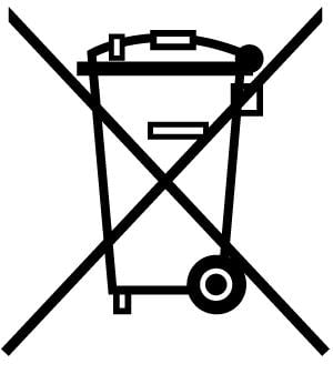
The Tektronix IsoVu® (TIVP) Generation 2 is a completely galvanically isolated probe tip cable, sensor head, and TekVPI interface as shown in the following figure. Hazardous voltages in the sensor head are completely isolated from the oscilloscope by optical fiber cables.
Compensation box
The TekVPI compensation box (comp box) connects the measurement system to one of the input channels on the oscilloscope. Power is supplied to the measurement system through the TekVPI interface of the oscilloscope. The buttons and indicators on the comp box provide a means for controlling the probe and indicating the overall status.
Sensor head
The sensor head provides an interface between the device-under-test (DUT) and the compensation box. It contains an electro-optic converter that converts the electrical signal from the sensor tip cables to an optical signal sent to the comp box.
Sensor tip cables
Several sensor tip cables options are available to connect the sensor head to the DUT:
-
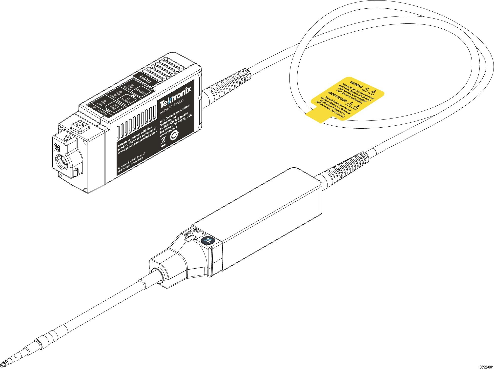
TIVPMX10X, 10X MMCX tip cable connector
-
TIVPMX50X, 50X MMCX tip cable connector
-
TIVPSQ100X, 100X 0.1-inch (2.54 mm) square pin connector
-
TIVPWS500X, 500X 0.2-inch (5.08 mm) square pin connector
-
TIVPMX1X, 1X MMCX tip cable connector
Models
The TIVP Series IsoVu Measurement System includes the following models:
- TIVP1. Tektronix IsoVu® Generation 2; 1 GHz Isolated Probe
- TIVP05. Tektronix IsoVu® Generation 2; 500 MHz Isolated Probe
- TIVP02. Tektronix IsoVu® Generation 2; 200 MHz Isolated Probe
- TIVP1L. Tektronix IsoVu® Generation 2; 1 GHz Isolated probe (10 m cable)
- TIVP05L. Tektronix IsoVu® Generation 2; 500 MHz Isolated probe (10 m cable)
- TIVP02L. Tektronix IsoVu® Generation 2; 200 MHz Isolated probe (10 m cable)
Supported oscilloscopes
The measurement system can only be used with the 4, 5, and 6 Series Mixed Signal Oscilloscopes with oscilloscope software version 1.28 or greater.
Accessories
This section lists the standard and optional accessories available for the measurement system.
Standard accessories
The following table list the accessories that are shipped with the probe.
| Accessory | Description | Part number |
|---|---|---|
 |
The 10X MMCX Tip is included in every TIVP. The MMCX tip is recommended for the best bandwidth and CMRR performance. 0.100" Square Pin and 0.200" Wide Square Pin tips are available as optional accessories. | TIVPMX10X |
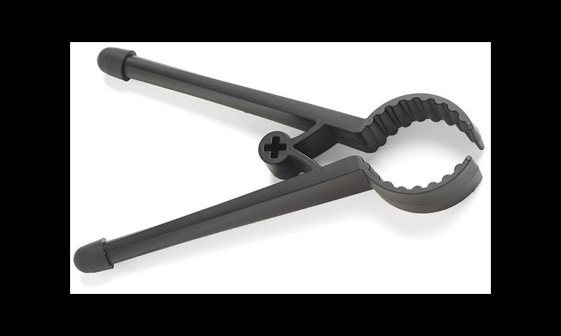 |
The Bipod is used to hold the probe. TIVP can rotate in the holder to accommodate square pin headers. | 352-1179-xx |
 |
The Probe Tip Adapter is used to adapt an MMCX IsoVu tip to standard 0.100" spaced, 0.025" square pins. | 131-9717-xx |
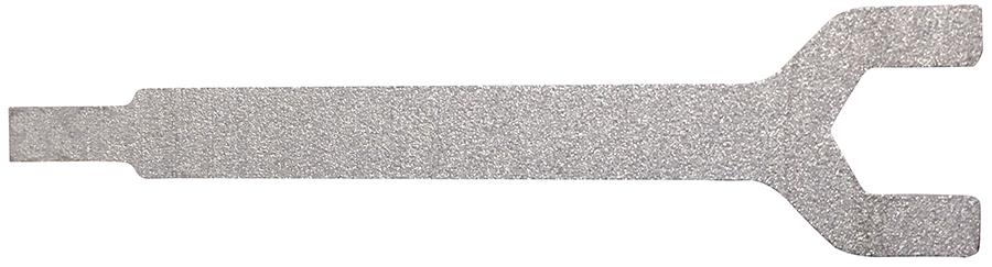 |
The SMA Wrench/Driver Tool is a 5/16" wrench for use on a SMA connector. | 003-1947-xx |
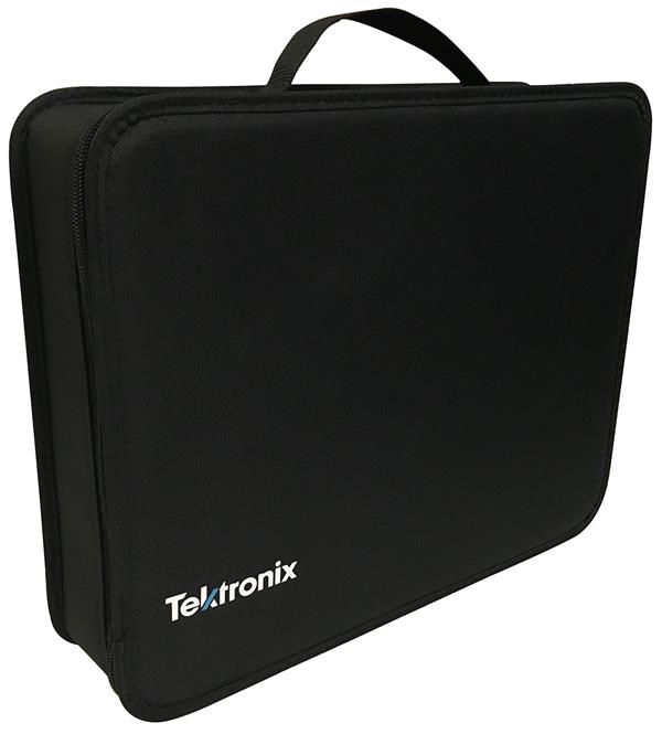 |
The Carrying Case is a soft case (with foam insert) that protects the TIVP and enforces the optical fiber minimum bend radius. | 016-2147-xx |
| 10 m version | 016-2149-xx |
Optional accessories
The following table lists optional accessories, such as other sensor tip cables are available.
| Accessory | Description | Part number |
|---|---|---|
 | 50X MMCX sensor tip cable | TIVPMX50X |
 | 100X sensor tip cable with 0.100" spaced square pin connector | TIVPSQ100X |
 | 500X sensor tip cable with 0.200" spaced wide square pin connector | TIVPWS500X |
 | 1X MMCX sensor tip cable | TIVPMX1X |
 | Square Pin to MMCX Adapter, 0.062" Spacing | 131-9677-xx |
 | Probe Tip Tripod Support | 352-1170-xx |
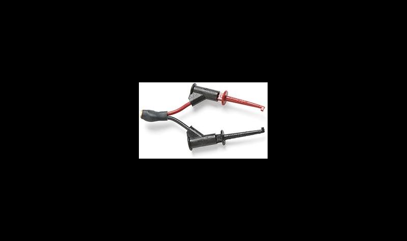 | Lead, MMCX to IC Grabber | 196-3546-xx |
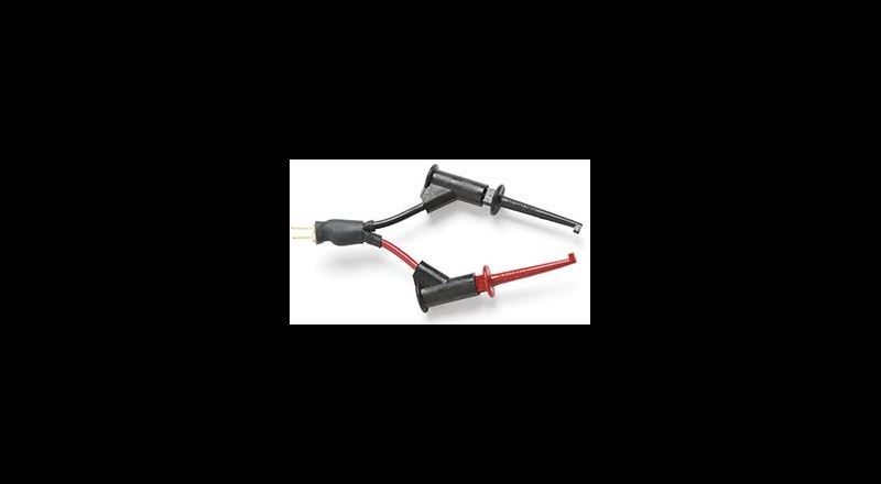 | Lead, Square Pin to IC Grabber | 196-3547-xx |
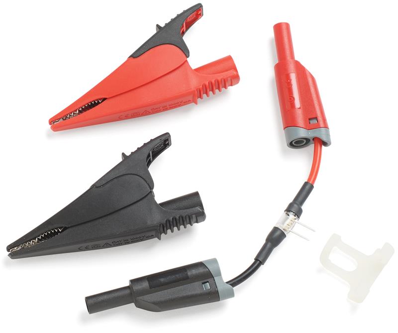 | Kit, Wide Square Pin to Banana Jack with Alligator Clamps and Support Brace | 020-3189-xx |
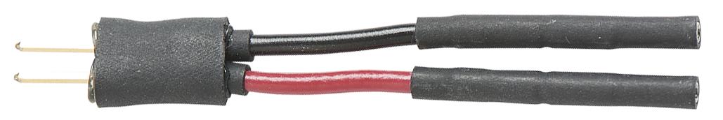 | Square Pin Y-lead | 196-3434-xx |
 | MicroCKT grabbers | 206-0569-xx |
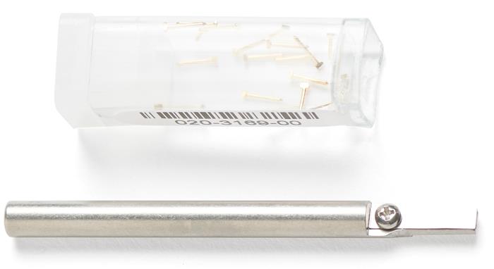 |
Spare Pins for 0.062" Spaced Test Points Solder Aid for 0.062" Spaced Square Pins |
020-3169-xx 003-1946-xx |
Operating information
This section to help you use the IsoVu™ probe safely and effectively. Read this section before installing your measurement system to be aware of the operating requirements and clearance requirements including possible hazardous areas when the measurement system is connected to the DUT.
Measurement system handling best practices
The measurement system consists of quality parts and should be treated with care to avoid damage or degrading the performance due to mishandling. Consider the following precautions when handling the fiber-optic cables and sensor tip cables.
- Do not crush, crimp, or sharply bend the fiber-optic cable. Avoid making loops in the fiber-optic cable smaller than 5 inches (12.7 cm).
- Do not twist the fiber-optic cable; twisting the cable will stress the optical fibers.
- Do not allow kinks or knots to develop in the fiber-optic cable.
- Avoid putting tension on the fiber-optic cable.
- Do not pull or jerk the fiber-optic cable, especially when kinks or knots are present.
- Do not drop the sensor head or comp box assembly since damage and misalignment of the internal optical components can result.
- Avoid over-bending the sensor tip cables; do not exceed the minimum bend radius of 2.0 inches (5.1 cm).
- Avoid crushing the cables by accidentally running over the cable with a chair wheel or by dropping a heavy object onto the cable.
- Never support the weight of the sensor head or comp box by the fiber-optic cable.
- Store the measurement system in the supplied carrying case when not in use.
Environmental requirements
The maximum operating environmental ratings for the measurement system when connected to a DUT and a Tektronix oscilloscope.
|
Feature |
Description | ||
|---|---|---|---|
| Temperature | Operating |
Comp box: 0° C to 30° C Probe head: 0° C to 50° C Tip Cable/Adapters: -40° C to 85° C | |
| Non-Operating |
Comp box: -20° C to +70° C Probe head: -20° C to +70° C Tip Cable/Adapters: -40° C to 85° C | ||
| Humidity | Operating |
Comp box: 5% to 85% RH (Relative Humidity) at up to +30° C, non-condensing Probe head: 5% to 85% RH (Relative Humidity) at up to +40° C, 5% to 45% RH above +40° C up to +50° C, non-condensing. Tip Cable/Adapters: 5% to 85% RH (Relative Humidity) at up to +85° C, non-condensing | |
| Non-Operating |
Comp Box/Probe Head: 5% to 85% RH (Relative Humidity) at up to +40° C, 5% to 45% RH above +40° C up to +85° C, non-condensing. Tip Cable/Adapters: 5% to 85% RH (Relative Humidity) at up to +85° C, non-condensing. | ||
| Altitude | Operating |
3000 m (9843 ft.) | |
| Non-Operating | 12,000 m (39370 ft.) | ||
Clearance requirements
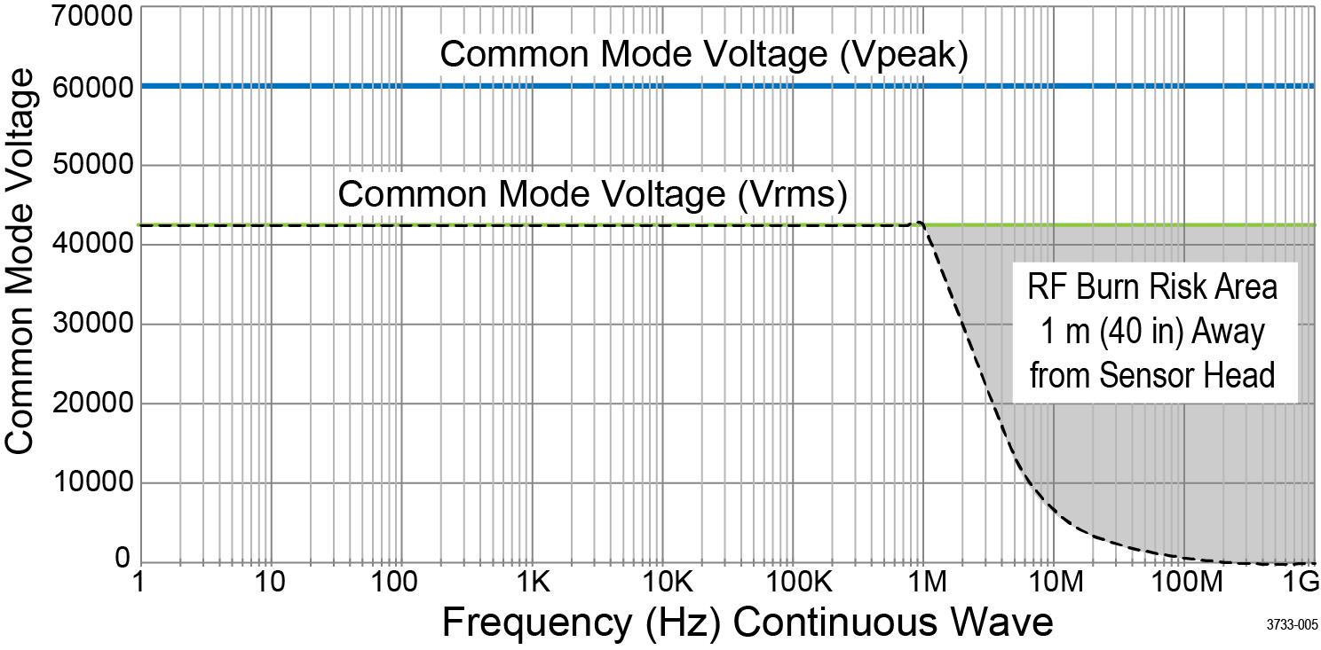
The unique common mode voltage range of the measurement system allows it to be used in the presence of high frequency/high voltage common mode signals. It is important to observe all precautions while using this product.
| WARNING:Electrical shock can occur while using this measurement system. The system is intended to isolate the operator from hazardous input voltages (common voltages); the plastic case of the sensor head and the shield on the sensor tip cable do not supply safe isolation. Maintain the safe clearance from the sensor head and sensor tip cable while the measurement system is connected to the energized circuit as recommended in this document. Do not access the RF Burn Hazard Zone while taking measurements on a live circuit. |
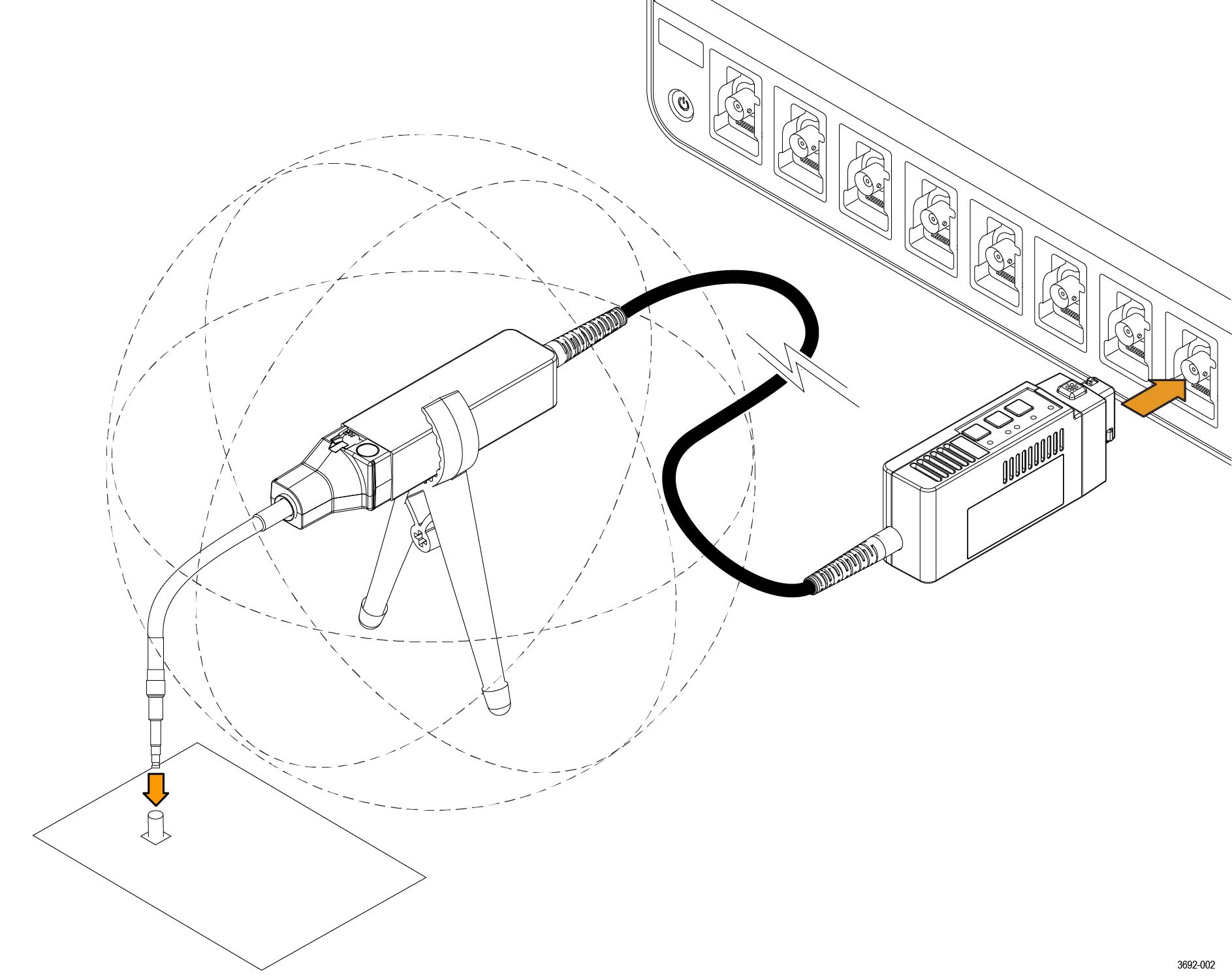
While measuring high frequency common mode signals, there is a risk of RF burns. Refer to the following derating curve to identify the danger areas. Measuring common mode signals within the gray shaded area can result in RF burns within 1 m (40 in.) of the sensor head and earth ground.
The following figure shows the components of the measurement system and the potential RF burn area when working with hazardous voltages. The RF burn area of 1 m (40 in.) is indicated by the dashed lines surrounding the sensor head.
Controls and indicators
A description of the controls and indicators on the compensation box.
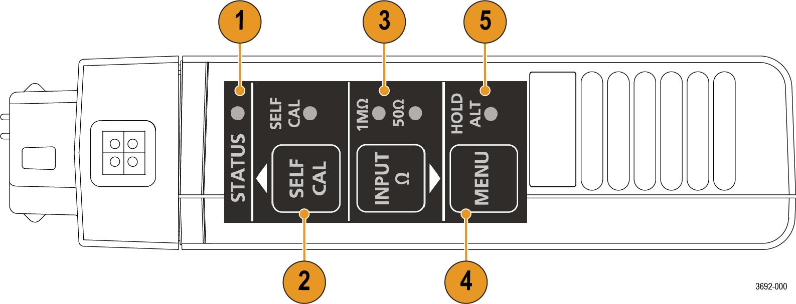
- STATUS indicator. For more information on the state of the LED, see Table 1
- SELF CAL button and LED indicator: Press to start self-calibration routine. For more information on the state of the LED, see Table 2
- INPUT Termination button and LED indicator: With no tip attached, press to toggle the sensor head between 50 Ω and 1 MΩ termination. For more information on the state of the LED, see Table 3
- MENU button: Press to open the Probe Vertical menu on the oscilloscope.
- ALT mode indicator: Displays special information about the probe. For more information, see Table 4
Cable flags
Flags on the cable provide high-level specifications for connecting to the DUT. They also provide a potential RF burn hazards warning and a self-calibration notification.
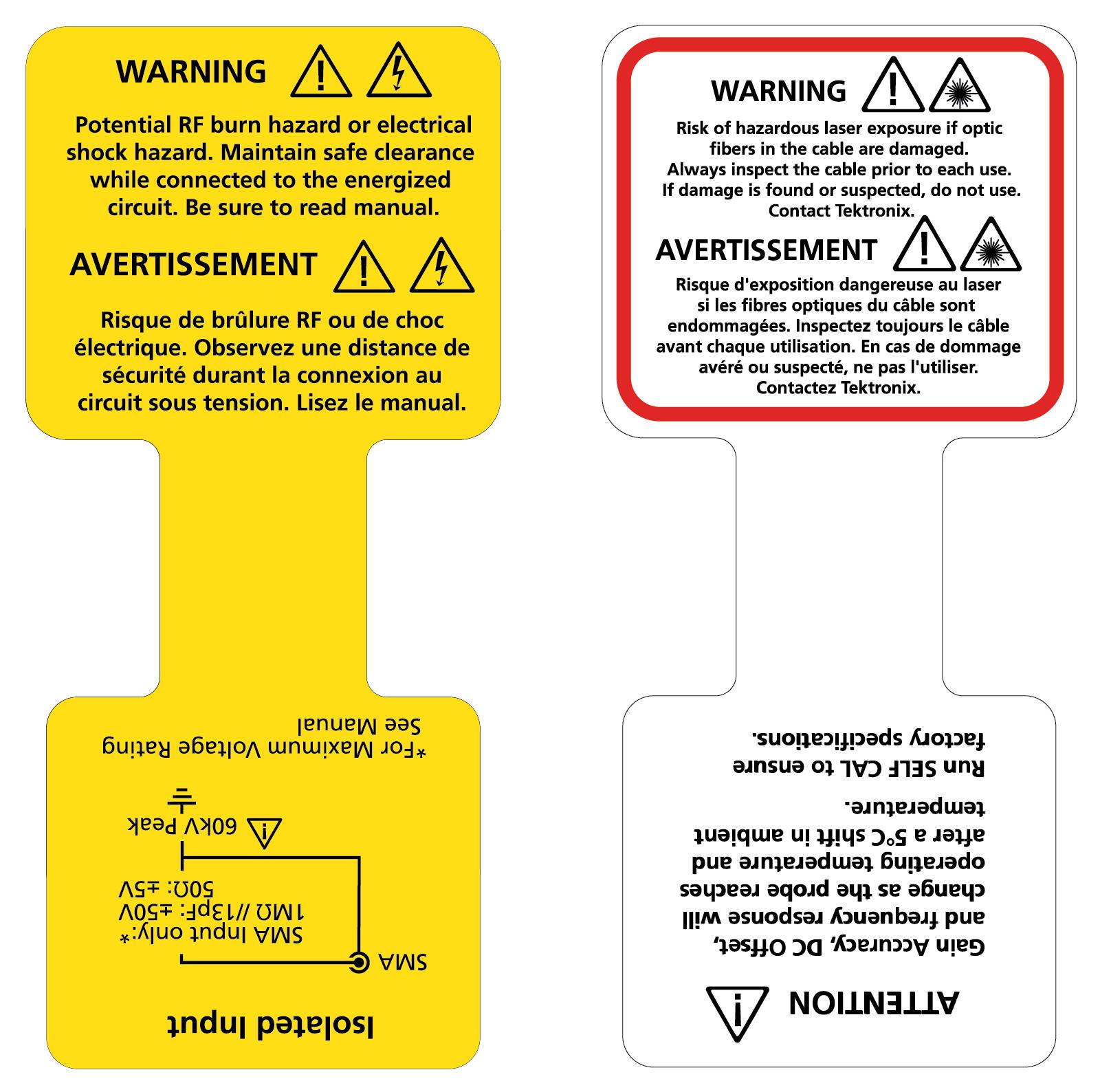
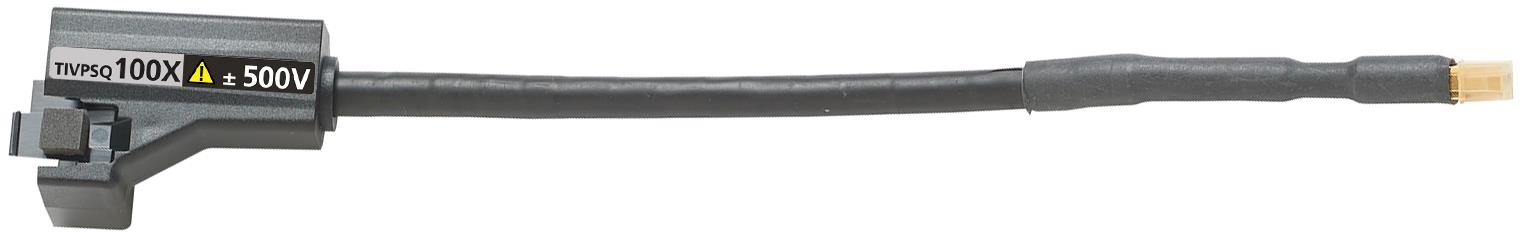
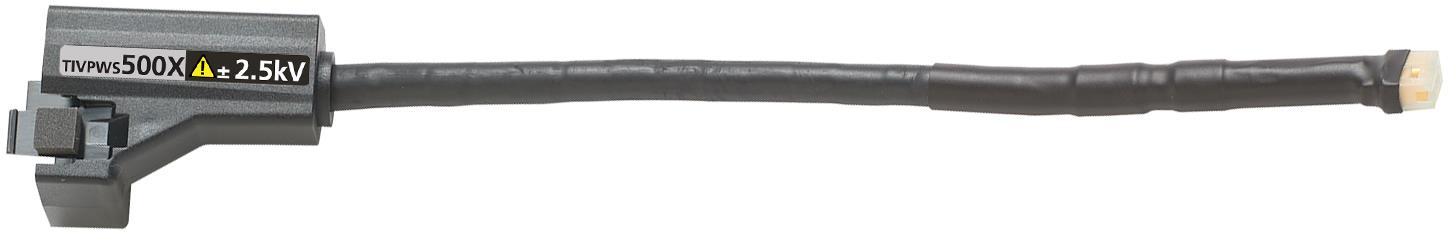
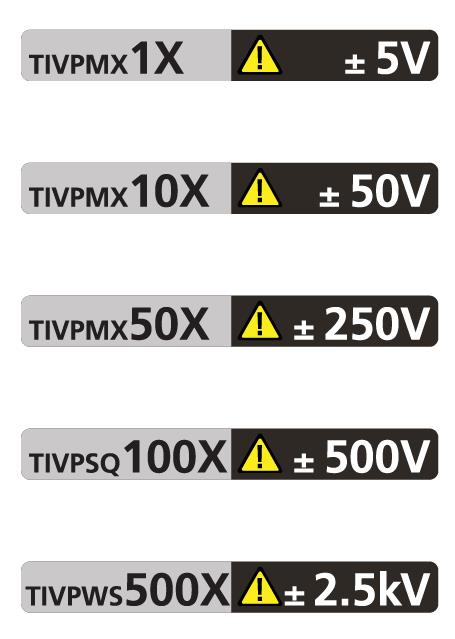
Sensor tip cable
Each sensor tip cable has a label that provides the maximum dynamic range and displays the attenuation factor.
Connecting to a circuit
| WARNING:This measurement system contains laser sources; exposing these laser sources may cause laser exposure. Except for the sensor tip cables on the sensor head, do not remove any plastic or metallic covers from the sensor head or comp box or attempt to disassemble the product. |
| WARNING:Do not connect the measurement system to an energized circuit to avoid the risk of shock. Always de-energize the circuit-under-test before installing or removing the tip cable from the circuit-under-test. The plastic case of the sensor head and the shield tip of the sensor cable do not supply the isolation. |
| WARNING:To avoid the risk of electrical shock or RF burns while the DUT is energized, do not touch the sensor head or sensor tip cable while taking measurements. Always keep a 1 m (40 in.) clearance from the sensor head during the measurement. Figure 2
Be sure to check the maximum ratings and derating curve for more information on the RF burn hazard zone. Figure 1 |
| CAUTION:To avoid possible damage to the equipment, do not connect the coaxial (common) shield of the sensor tip cable or SMA input to the high impedance portion of a circuit. The additional capacitance can cause circuit damage. Connect the coaxial (common) shield to the low impedance section of the circuit. |
| Note:Touching the sensor head or sensor tip cable when measuring a high frequency common mode signal increases the capacitive coupling and can degrade the common mode loading on the circuit-under-test. |
| WARNING:To prevent the arc flash caused by a different potential, do not place the sensor head or sensor tip cable on the circuit that has the different voltage. |
The following steps describe the process for connecting the measurement system between an oscilloscope and the DUT.
-
Verify the DUT is not connected to an energized circuit.
-
Connect the compensation box to one of the channels on the oscilloscope.

-
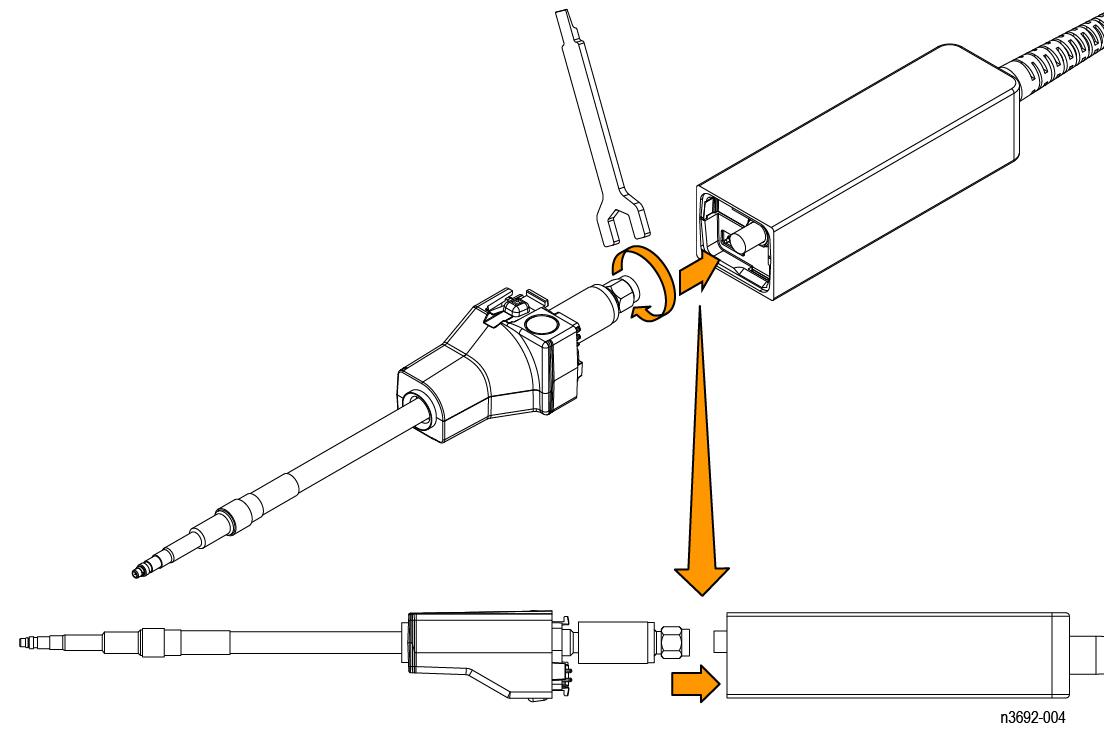
Install the sensor tip cable to the sensor head.
-
Line up the sensor tip cable with the sensor head.
Take care to avoid bending or twisting the sensor tip cable assembly during this process.
-
Connect the SMA connector of the sensor tip cable to the sensor head. Use the SMA wrench to tighten the SMA cable to 4 to 5-in lbs.
Use the adjustment tool that was shipped with your probe.
Figure 1. Connecting the sensor tip cable to the sensor head -
-
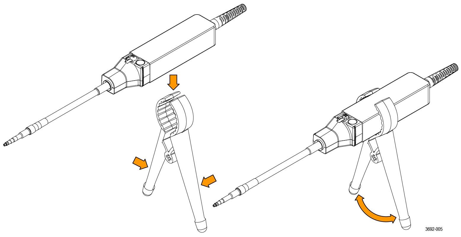
Connect the sensor head to the included bipod or a similar support.
This support keeps the sensor head steady reducing the potential mechanical stresses at the electrical connection point of the DUT. The support also keeps the sensor head away from surrounding circuits and conductive objects to minimize the parasitic capacitive coupling to these surroundings.
Figure 2. Connect the sensor head to the bipod Note:To obtain the most accurate measurement, allow the measurement system to warm up for 20 minutes. Then perform the self-calibration before connecting the tip cable to the DUT and taking the measurement. -
Connect the sensor tip cable end to the DUT. If you are using MMCX sensor tip cable, connect it to an MMCX connector on the DUT or to a square pin adapter on the DUT. The adapters connect to square pins with either 0.100-inch (2.54 mm) spacing or 0.062-inch (1.57 mm) spacing. Figure 1
If you are using one of the square pin sensor tip cables, connect it directly to the square pins on the DUT. Connecting the sensor tip cables
-
Set up the controls on the oscilloscope.
-
Apply power to the DUT to take the measurement.
Self-calibration
The TIVP contains a self-calibration function that corrects gain accuracy, DC offset, and frequency response. These parameters change as the probe warms up to the operating temperature and remain constant once the temperature reaches steady-state. After the probe warms up, self-calibration is recommended when there is a 5°C change in ambient temperature. An indicator LED on the compensation box provides the status of the self-calibration. See the Controls and indicators for more information on the LEDs.
To check the status of the self-calibration programmatically, use the SELFCAL:STATE? PI command to determine whether a self-calibration is RECOMMENDED, RUNNING, or PASSED.
Before performing critical measurements, run a self-calibration to ensure the probe is compensated.
| Note:The sensor tip cable does not need to be removed from the test point to successfully complete the self-calibration. |
- Connect probe to an oscilloscope channel.
- Press the SELF CAL button on the probe compensation box. The Self Cal indicator LED will blink while self-calibration is in process.
- Self-calibration is complete when the indicator LED displays green.
To run the self-calibration programmatically, use the CH<x>:PROBE:SELFCAL EXECUTE PI command. The connected channel is specified by "x".
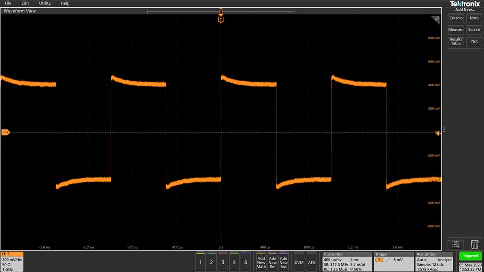
The TIVP probe takes about 20 minutes to warm up. During this time, acquired waveforms may show obvious aberrations. The following screen shot shows how a 1 KHz square wave appears at the beginning of the warm-up period. Notice how the probe appears to be uncompensated.
| Note:When moving a probe that has fully warmed up to a new oscilloscope channel, you must give the probe another 5 minutes to warm up on the new channel. |
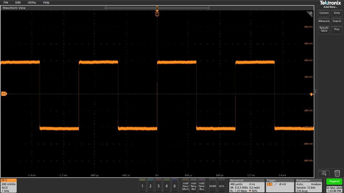
After 20 minutes, most of the aberrations are gone. Self-calibration can be used before the probe reaches its operating temperature, however those self-calibration settings will become invalid a few minutes later as the internal temperature changes.
Self-calibration takes less than 2 minutes to complete. Your signal does not need to be disconnected from the probe head when running self-calibration. The LED next to the SELF CAL button on the compensation box will flash yellow during the operation. When complete, the LED will either turn green (passed) or red (failed).
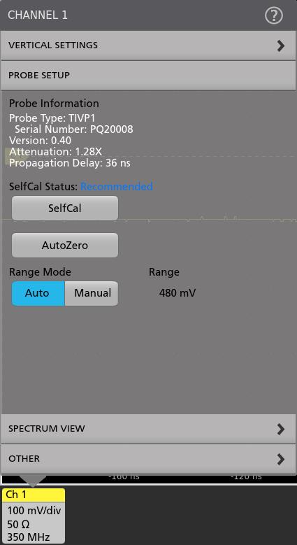
The SelfCal Status indicator in the oscilloscope Probe Setup menu indicates whether self-calibration is required.
| Note:In 4/5/6 Series Mixed Signal Oscilloscopes, commands are available to start and monitor self-calibration and a status query to determine if self-calibration is needed. |
AutoZero
AutoZero and self-calibration work on different parts of the measurement system. Self-calibration optimizes measurements through adjusting parameters in the probe. AutoZero is an oscilloscope function and is used when a displayed waveform is not centered correctly (for example; due to a small DC offset error). AutoZero automatically runs after self-calibration. It is not necessary to disconnect your signal from the probe when running a self-calibration. However, when AutoZero is run by itself, the signal must not be present.
When the TIVP changes between its internal ranges it may be beneficial to run an AutoZero from the oscilloscope. The TIVP internal range will change in Auto Range mode when the Vertical scale of the oscilloscope is changed. The probe internal range will also change in Manual Range mode if a different range is selected from the Probe Setup menu in the channel vertical settings.
Menu button
Press the MENU button on the comp box to view the Probe Setup menu on the oscilloscope.
Use the menu options on the oscilloscope to change the probe settings.
Ranges
The measurement system has a variety of ranges available for you to select, whether the probe is being used with or without a tip. This allows for tradeoffs to be made between noise and dynamic range depending on the needs of the measurement being made.
| CAUTION:To avoid damaging the probe, do not exceed the Peak Voltage rating for a given tip or the probe head. The Maximum Non-Destruct Voltage limit (Peak Voltage) does not increase when the Probe Ranges are changed. For example, the TIVPMX50X limit of ±250 Vpk is the same for all range settings. |
In 4, 5, and 6 Series oscilloscopes, 9 ranges are selectable when Range Mode is set to Manual. The recommended V/div settings are displayed in the table below. The ranges shown are for the probe SMA input and 1X tip. Multiply the range and V/div setting by the tip attenuation to get the values for a sensor tip cable.
| 4/5/6 Series MSO probe ranges | Recommended V/div setting |
|---|---|
| 20 mV | 2 mV/div |
| 40 mV | 5 mV/div |
| 80 mV | 10 mV/div |
| 160 mV | 20 mV/div |
| 320 mV | 50 mV/div |
| 640 mV | 100 mV/div |
| 1.28 V | 200 mV/div |
| 2.56 V | 500 mV/div |
| 5 V | 1 V/div |
When using a tip, the label of each sensor tip cable shows the maximum dynamic range and the attenuation factor. For example, the TIVPMX10X has a 10X attenuation factor and displays a signal with a ±50 V differential voltage. When more sensitive ranges are selected, dynamic range is limited. Refer to the Linear differential input voltage range in the specifications table for more information.
Auto Range
In 4, 5, and 6 Series oscilloscopes, the Range Mode is selectable for either Auto Range, or Manual. With the Range Mode set to Auto Range, the probe range is automatically selected when the V/div knob on the oscilloscope is turned. The relationship between probe range and V/div setting matches that shown in Table 1.
Selecting a sensor tip cable
| CAUTION:Avoid over-voltage conditions that can damage or degrade the sensor head input termination by selecting the correct sensor tip cable. Selecting the correct sensor tip attenuation factor is crucial to ensure that the sensor head input termination is not degraded or damaged by an over-voltage condition. Select the sensor tip cable that will provide the lowest attenuation possible for the signal being measured. |
When selecting a sensor tip cable for a particular application, consider the following questions:
-
What is the maximum RMS/Peak Voltage at the test point being measured (for example, under a fault condition)?
-
What is the minimum single-ended input resistance that my circuit can tolerate?
-
How large of a signal do I want to display at one time on the oscilloscope?
-
What sensitivity do I need (for example, the minimum V/div setting)?
The following table will help you select the correct sensor tip cable. Start at the top of the table and work down. Choose the first tip that meets all of your criteria.
| Sensor tip cable | Most sensitive V/div setting | Dynamic range | Maximum non-destruct voltage (DC + pk AC) | Single-ended input resistance |
|---|---|---|---|---|
| TIVPWS500X | 500 mV | ±2500 V | 3300 Vpk | 40 MΩ |
| TIVPSQ100X | 100 mV | ±500 V | 600 Vpk | 9.75 MΩ |
| TIVPMX50X | 50 mV | ±250 V | 300 Vpk | 9.75 MΩ |
| TIVPMX10X | 10 mV | ±50 V | 250 Vpk | 10 MΩ |
| TIVPMX1X | 1 mV | ±5 V | 100 Vpk / 5 VRMS | 1 MΩ / 50 Ω |
| SMA Input 1 MΩ | 1 mV | ±5 V | 100 Vpk | 1 MΩ |
| SMA Input 50 Ω | 1 mV | ±5 V | 5 VRMS | 50 Ω |
For maximum non-destruct voltage refer to the Maximum differential input voltage vs frequency derating graphs.
Deskew
Each probe comes loaded with nominal propagation delay values that can be automatically applied through the Vertical menu on the oscilloscope. Deskew accuracy can be improved using a known signal and a deskew fixture. When the timing relationships between waveforms is critical, always deskew your test system with known equipment.
Input offset
The measurement system provides an adjustable input referred offset voltage. This enables viewing a portion of the signal that is off-screen or examining sensitive behavior riding on a larger differential voltage. For example, a 0 V to 600 V step would normally exceed a ±500 V input range. By applying 300 V of offset, the 600 V step is brought into the dynamic range of the probe and can be viewed accurately. Offset is applied by the probe and has a much greater range than the oscilloscope alone.
Input coupling AC or DC
The TIVP sensor head contains both DC and DC Reject input coupling modes. By default, DC coupling is enabled; the mode is switchable through the scope interface or PI command.
The DC input coupling setting provides a direct, DC coupled, electrical path in the sensor head; it accepts all types of signals, including unchanging DC voltages, time-varying DC voltages, AC, and combinations of AC and DC.
When DC input coupling is selected, any applied offset is injected at the sensor head and the offset range depends on the attached tip cable attenuation.
DC Reject input coupling setting provides an AC- only path in the sensor head, removing DC offset from any mixed signal to view the AC component of the signal. DC reject is useful when you measure small amplitude signals superimposed on a large differential offset component.
With DC Reject enabled, offset is applied at the oscilloscope input and is limited by the offset capability of the specific Volts/Div setting on the oscilloscope multiplied by the selected tip attenuation.
Voltage range
The TIVP is designed to enable characterization of high frequency circuits with a wide range of differential voltages in the presence of common mode voltages. Understanding the limits and differences between the voltage ratings as discussed in this section is essential to optimize signal fidelity and measurement accuracy.
Although the common mode voltage range of the probe is very large (>60 kV), the differential input range is limited and depends on the tip attenuation, the gain range selected, and the applied offset.
The input voltage conditions are divided into several different input ranges.
Common mode voltage range
TIVP sensor head is optically isolated from earth ground, making the common mode input range >60 kV. The differential input range is more limited and refers to the signal that can be applied across the probe tip, regardless of the common mode voltage.
Offset voltage range
Offset voltage can be applied through the oscilloscope Vertical menu settings. The input offset capability of the probe extends from ±25 V to ±2500 V depending on the tip used. This offset is applied at the sensor head of probe and can be useful to bring applied signals within the dynamic range (Vdiff) of the probe.
Maximum non-destruct differential voltage range
The maximum non-destruct differential input range is the maximum differential voltage that can be applied to the input without damaging the probe. This is a DC +peak AC rating (no portion of the differential input signal should exceed this value). The maximum non-destruct differential voltage varies from ±20 V to ±2500 V depending of the sensor tip cable being used. Exceeding these levels will cause permanent damage to components of the sensor head. Additionally, the TIVPMX1X and SMA input also have VRMS limits.
Connecting the sensor tip cables
Tektronix provides different types of sensor tip cables to connect to the circuit board.
The MMCX sensor tip series connect directly to MMCX connectors on the circuit board or to probe tip adapters installed on the circuit board. Installing the probe tip adapters
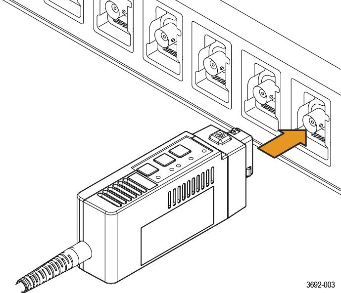
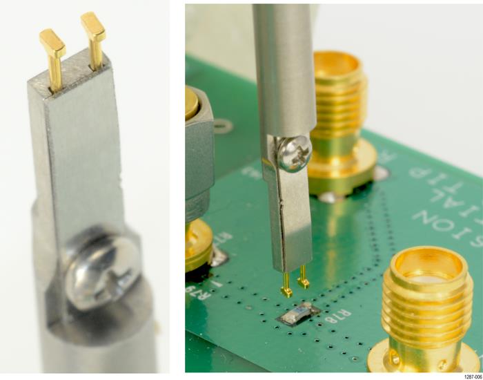
The square pin series sensor tip cables connect directly to the circuit board as shown in the following figure.
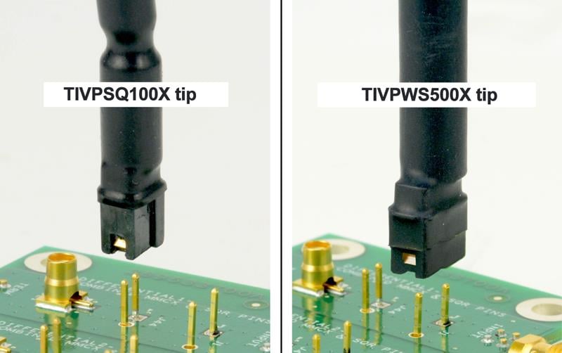
The SQPIN series sensor tip cables connect to 0.1-inch (2.54 mm) square pins on the circuit board. The WSQPIN series sensor tip cables connect to 0.2-inch (5.08 mm) square pins on the circuit board.
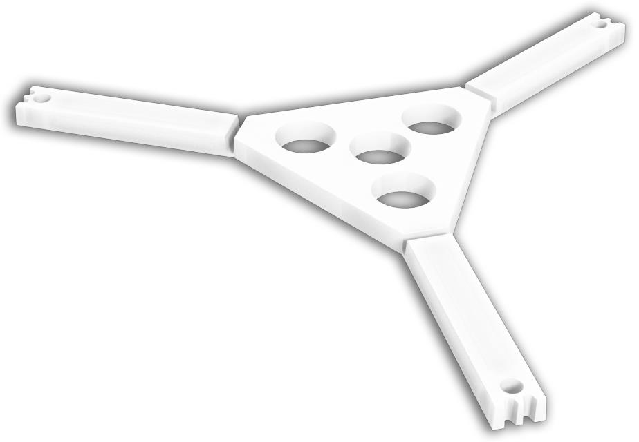
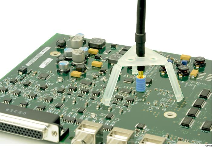
Probe tip tripod
Use the probe tip tripod to connect the sensor tip cables to adapters on the circuit board. This tripod has flexible hinges to easily position the probe tip cable above the adapter on the circuit board. Tektronix recommends gluing the tripod in place on the circuit board to provide additional support for the sensor tip cables. The following figure shows an example of connecting to an adapter on the circuit board with the tripod; it reduces stresses on the test point.
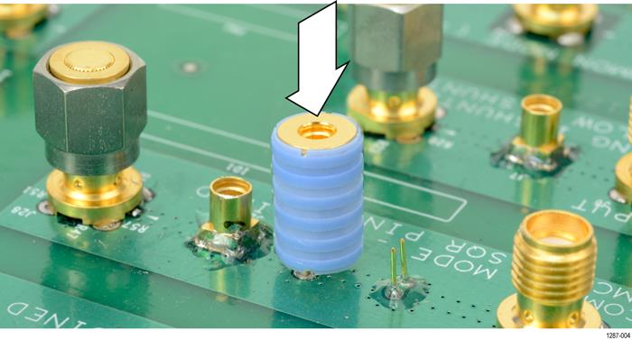
Installing the probe tip adapters
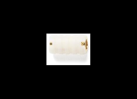
Tektronix provides two probe tip adapters to connect the MMCX sensor tip cables to pins on the circuit board. The MMCX-to-0.1-inch (2.54 mm) pitch adapter and the MMCX-to-0.062-inch (1.57 mm) pitch adapter.
One end of each adapter has an MMCX socket for connection to an IsoVu MMCX tip cable. The other end of the adapter has a center pin socket and four common (shield) sockets around the outside of the adapter. Notches on the adapters can be used to locate the shield sockets. The procedure for installing these adapters are the same, the main difference is the spacing of the pins on the circuit board.
To install the adapters onto the square pins, line up the center of the adapter with the signal source pin on the circuit board. Use the notch on the adapter to align one of the shield sockets to the common pin on the circuit board. The following figures show examples of lining up the adapters on the circuit board.
To achieve the best electrical performance, especially the CMRR performance and EMI susceptibility, place the probe tip adapter as close as possible to the circuit board.
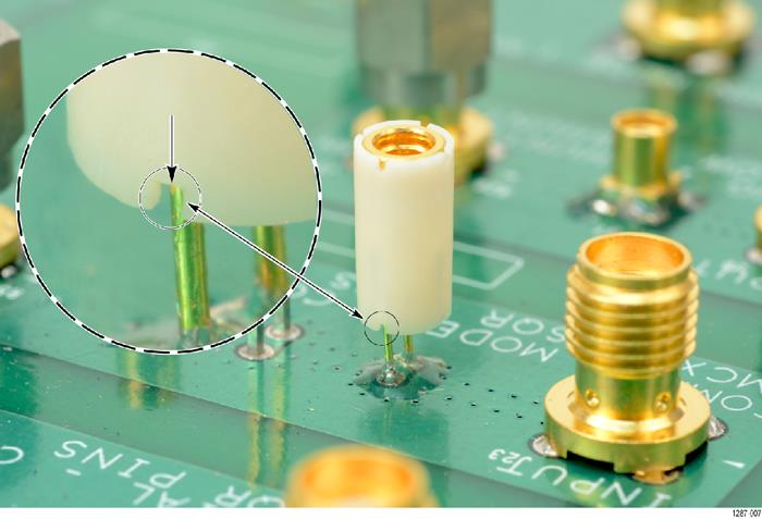
After lining up the adapters gently push down on the adapter to seat it in place on the circuit board.
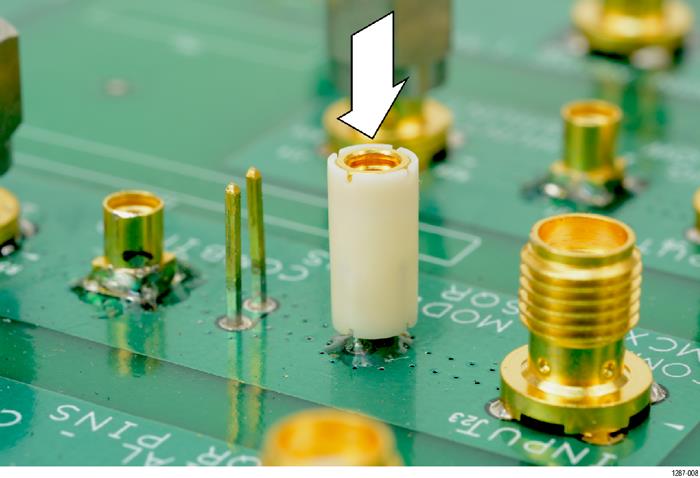
When the adapters are firmly in place on the circuit board connect the sensor tip cable to the top of the adapter while using the probe tip tripod to ease the tension off the probe tip cable and adapter. Figure 1
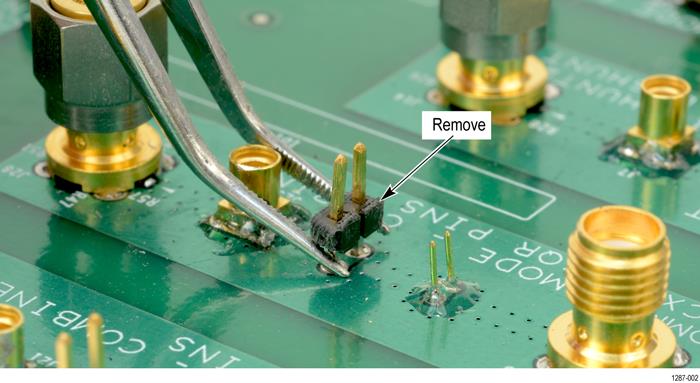
Installing the square pins on the circuit board
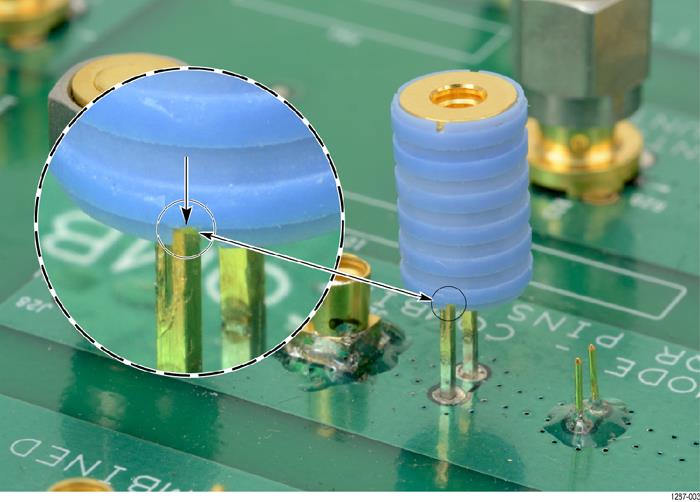
The following figure shows the recommended clearance requirements for connecting the adapters to the square pins on the circuit board. The bottoms of the adapters are shown at the top.
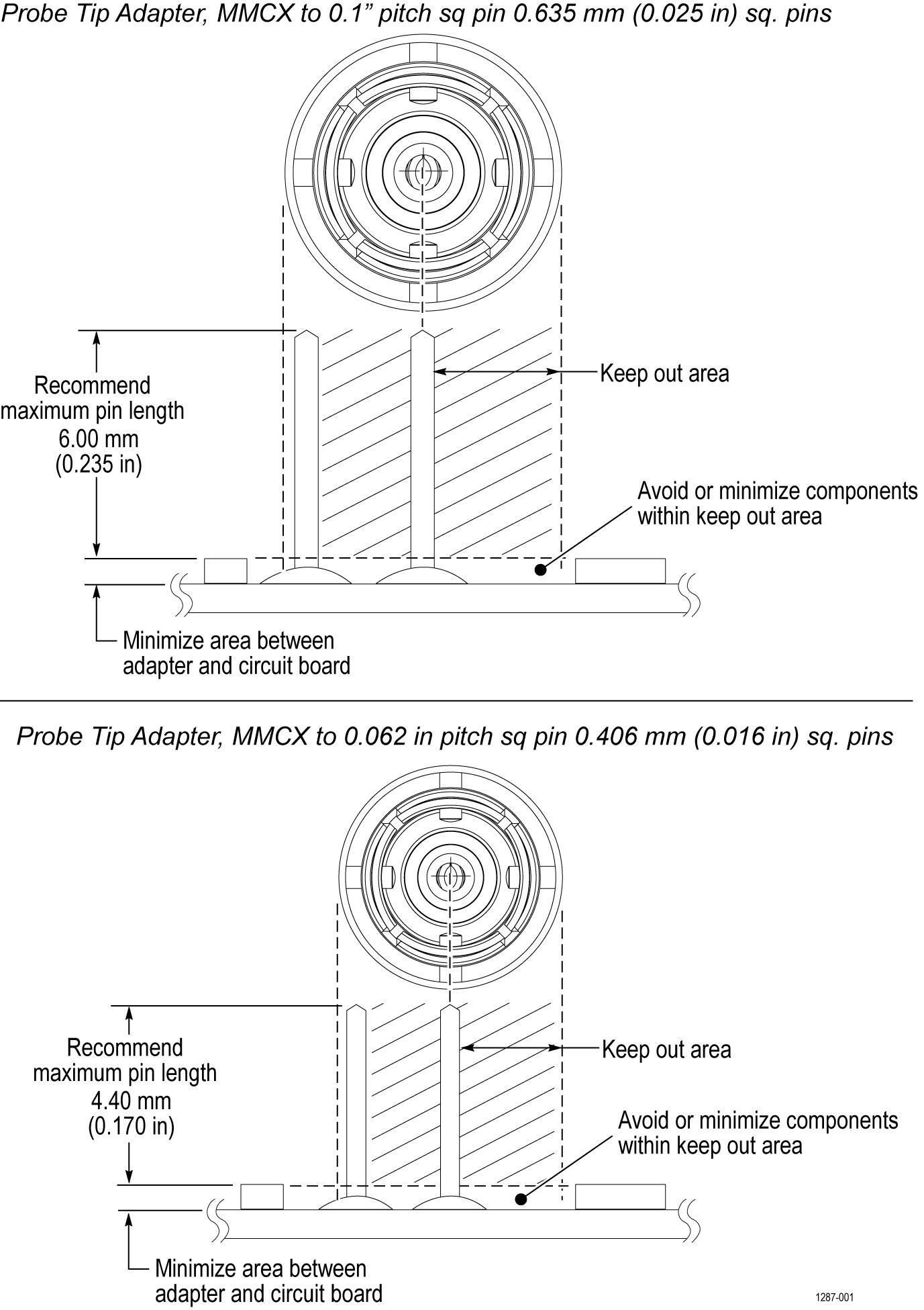
The 0.025-inch (0.635 mm) square pins should already be located on the circuit board. Some square pins might have headers installed on the circuit board. Tektronix recommends removing the plastic spacer from the square pins to gain closer access to the circuit board as shown in the following figure to achieve the best electrical performance, especially CMRR. You might need to use a pair of tweezers to remove the spacer as shown in the figure.
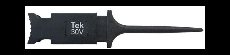
Tektronix provides a set of solder pins (0.018-inch (0.46 mm) diameter) to install on the circuit board for use with the MMCX to 0.062-inch (1.57 mm) adapter. Use the soldering aide tool accessory (Tektronix part number, 003-1946-xx) to install these pins on the circuit board.
| Note:The solder pins are extremely small and can be challenging to handle. Tektronix recommends using tweezers and a magnifying tool when installing the pins on the circuit board.
The solder pins can be installed around a surface mounted component on the circuit board, but adequate clearance should be maintained for a good electrical connection for the adapter. Figure 1 |
| Note:The coaxial (common) shield of the sensor tip cable and tip adapters should always be connected to the lowest impedance point (usually a circuit common or power supply rail) in the circuit-under-test (relative to the sensor tip cable/center conductor) to obtain the most accurate waveform.
|
Use the following steps to install the solder pins using the soldering aide on the circuit board:
-
Carefully insert the solder pins into the soldering aide as shown in the following illustration.
Figure 3. Using the soldering aide to install the square pins on the circuit board -
Use the soldering aide to hold the square pins in place while soldering the square pins to the circuit board.
-
If necessary apply a small amount of adhesive to further strengthen the connection to the circuit board. However, keep the height of the adhesive to a minimum to provide good electrical contact for the adapter. Figure 1
Specifications
The following tables list the specifications for the measurement system. The specifications are Typical unless noted otherwise.
The performance limits in this specification are valid with these conditions:
-
The instrument must be in an environment with temperature, altitude, and humidity within the operating limits described in these specifications.
-
The instrument must have had a warm-up period of at least 20 minutes.
-
The measurement system is powered from a TekVPI compatible oscilloscope.
Warranted specifications describe guaranteed performance with tolerance limits or certain type-tested requirements.
The performance verification procedures are listed later in this document. Performance verification procedures
Overview
| Characteristic | TIVP1 | TIVP05 | TIVP02 |
|---|---|---|---|
| Bandwidth | 1 GHz | 500 MHz | 200 MHz |
| Rise time | 450 ps | 850 ps | 2 ns |
- Differential Input Voltage Range, Offset Range, Single-ended Impedance
-
Use only the sensor tip cables listed.
Sensor tip cable Differential input voltage range Offset range Single-ended input impedance SMA Input (50 Ω mode) ±5 V ±25 V 50 Ω || N.A. SMA Input (1 MΩ mode) ±5 V ±25 V 1 MΩ || 11 pF TIVPMX10X ±50 V ±200 V 10 MΩ || 2.8 pF TIVPMX50X ±250 V ±250 V 9.75 MΩ || 2.3 pF TIVPSQ100X ±500 V ±500 V 9.75 MΩ || 3.5 pF TIVPWS500X ±2.5 kV ±2.5 kV 40 MΩ || 2.4 pF TIVPMX1X ±5 V ±25 V 50 Ω or 1 MΩ || 28 pF
- Common Mode Rejection Ratio
-
Approximately 20 dB lower in ±5 V Range, except at DC.
Sensor tip cable DC 1 MHz 100 MHz 200 MHz 500 MHz 1 GHz SMA Input (50 Ω mode) 160 dB 145 dB 100 dB 100 dB 100 dB 90 dB SMA Input (1 MΩ mode) 160 dB 145 dB 100 dB 100 dB 100 dB 90 dB TIVPMX10X 160 dB 115 dB 92 dB 90 dB 85 dB 80 dB TIVPMX50X 160 dB 110 dB 80 dB 80 dB 80 dB 70 dB TIVPSQ100X 160 dB 105 dB 60 dB 50 dB 35 dB 25 dB TIVPWS500X 160 dB 90 dB 50 dB 40 dB 20 dB 10 dB TIVPMX1X 160 dB 125 dB 115 dB 110 dB 100 dB 90 dB
- Maximum Non-Destructive Differential Voltage
- Derated with frequency; refer to the Maximum differential input voltage vs. frequency derating graph in the Specifications section of the TIVP Series IsoVu Measurement System User Manual.
- Common mode voltage range
- 60 kV peak
- Common mode input impedance (Typical)
-
- Input resistance
- Galvanically isolated through the fiber optic connection
- Input capacitance
- <2 pF
- DC gain accuracy
-
- Differential DC gain accuracy
- <1.5% after self-cal; additional 4.5% within 4C of self-cal
- System noise (rms)
-
Sensor tip cable ±20 mV range (most sensitive) ±320 mV range ±5 V range (widest range) SMA Input (50 Ω mode) 0.43 mV rms 1.46 mV rms 48 mV rms SMA Input (1 MΩ mode) 0.43 mV rms 1.46 mV rms 48 mV rms TIVPMX10X 4.3 mV rms 14.6 mV rms 480 mV rms TIVPMX50X 21.5 mV rms 73 mV rms 2.4 V rms TIVPSQ100X 43 mV rms 146 mV rms 4.8 V rms TIVPWS500X 215 mV rms 730 mV rms 24 V rms
- Propagation delay
-
- 2 meter cable
- 18.3 ns
- 10 meter cable
- 63.7 ns
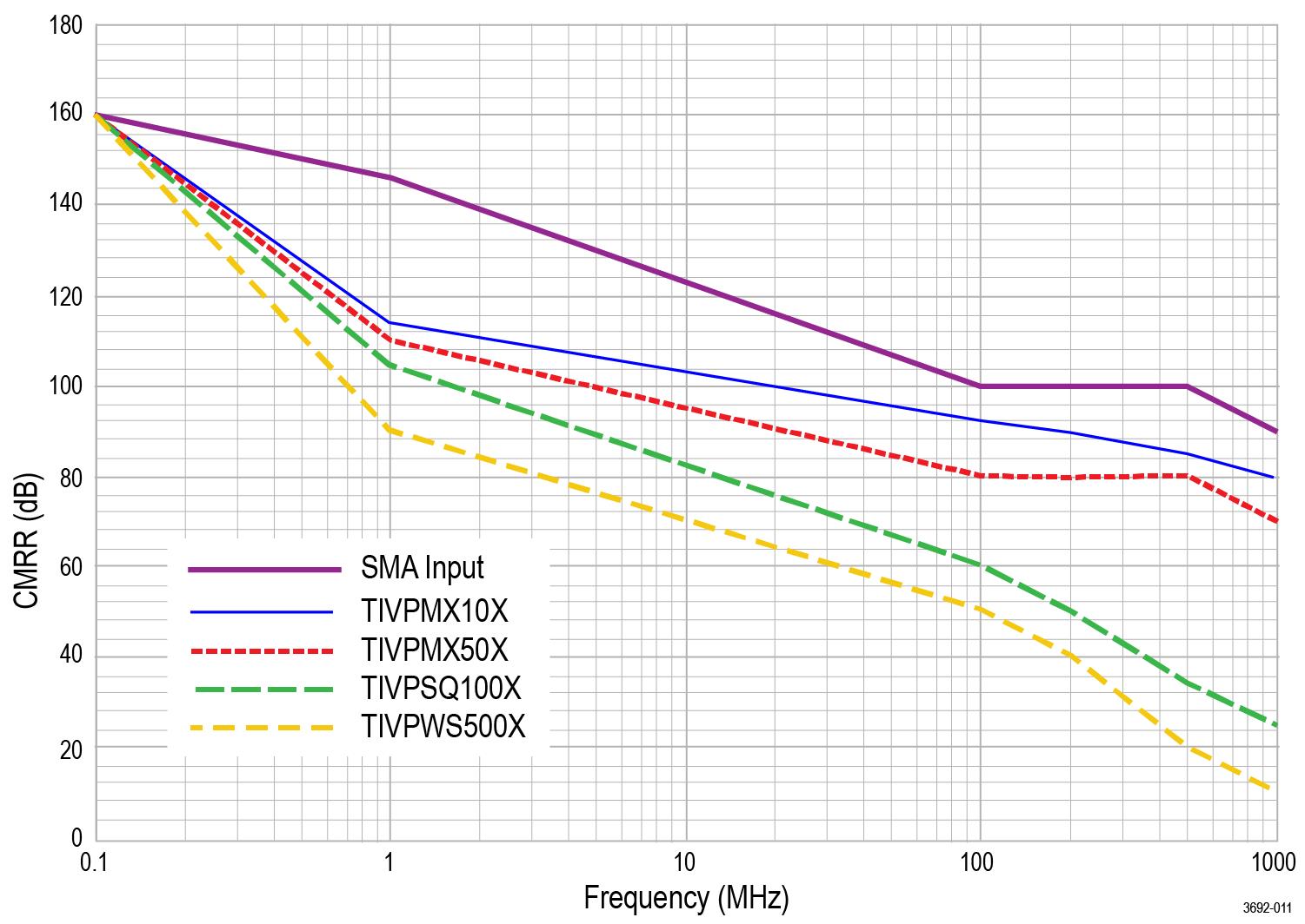
Common mode rejection ratio graphs
The ability to measure common mode rejection ratios (CMRR) of the IsoVu system below 100 kHz is limited by the dynamic range of test systems. Due to the optical isolation of the IsoVu sensor head, the DC CMRR performance of all tip cables is expected to be greater than 160 dB.
The following figure shows the typical CMRR values for the supported sensor tip cables.
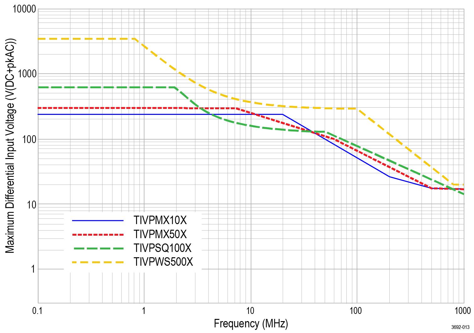
Maximum differential input voltage vs frequency derating graphs
The following figure shows the derating values for the supported sensor tip cables.
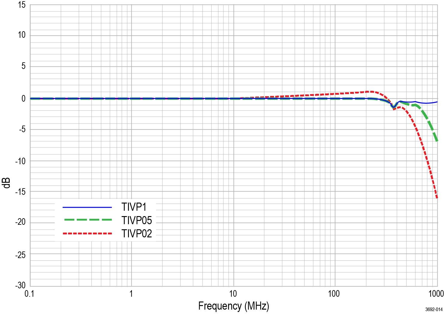
Frequency response graph
The following figure shows the frequency response for each probe.
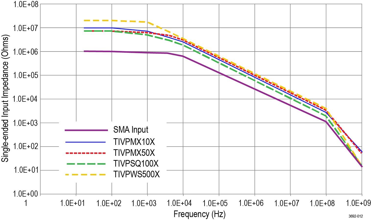
Single-ended input impedance graphs
The following figure shows the single-ended input impedance vs. frequency values for the supported sensor tip cables.
TIVP physical specifications
|
Characteristic |
Description |
|---|---|
|
Net weight (Weight does not include accessories and packaging.) | Tip cable assembly: 25g (0.055 lb) |
| Probe head: 0.363 kg (0.8 lbs) | |
| Compensation box: 0.816kg (1.8lbs) | |
|
Sensor tip cables |
0.025 kg (0.055 lb) |
| Sensor tip cable length | 20.03 cm (7.886 inches) |
| Fiber cable length |
2 meter (6.56 ft) 10 meter (32.81 ft) |
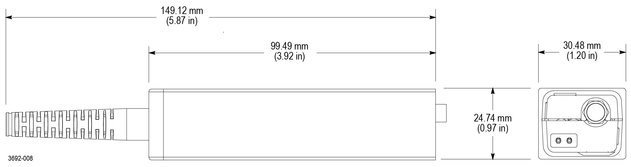
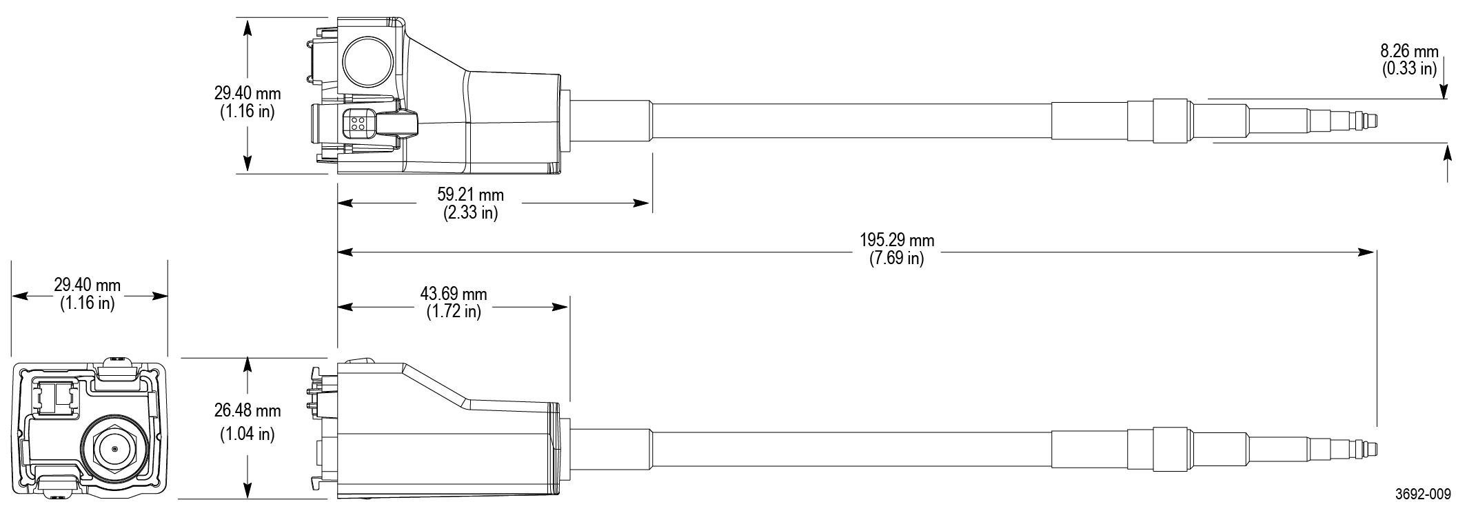
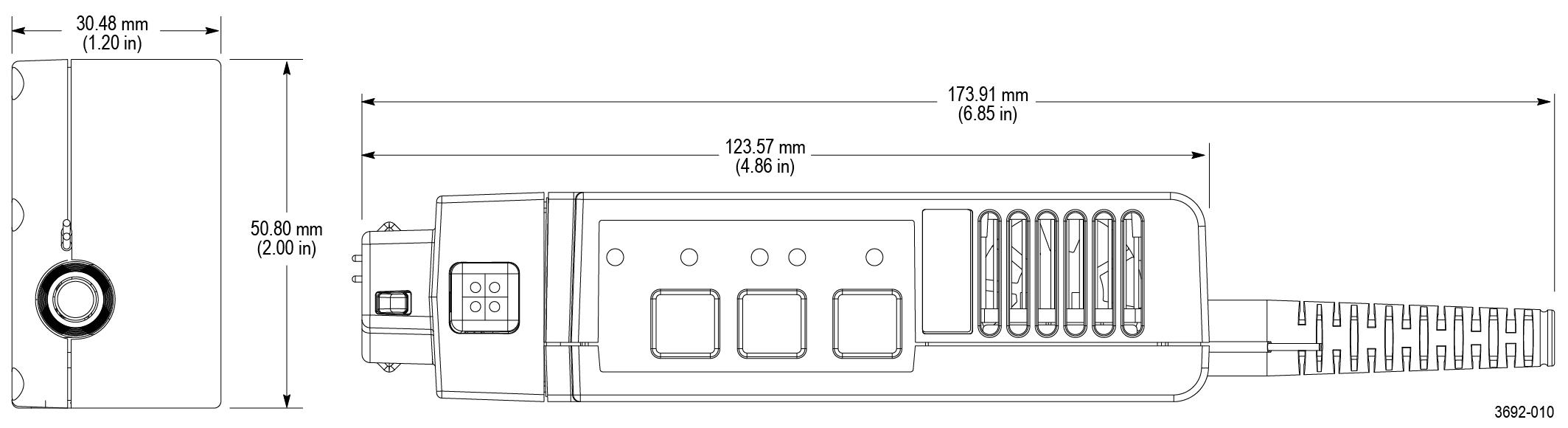
Probe dimensions
IsoVu measurement system block diagram
The following figure shows a block diagram of the IsoVu measurement system.
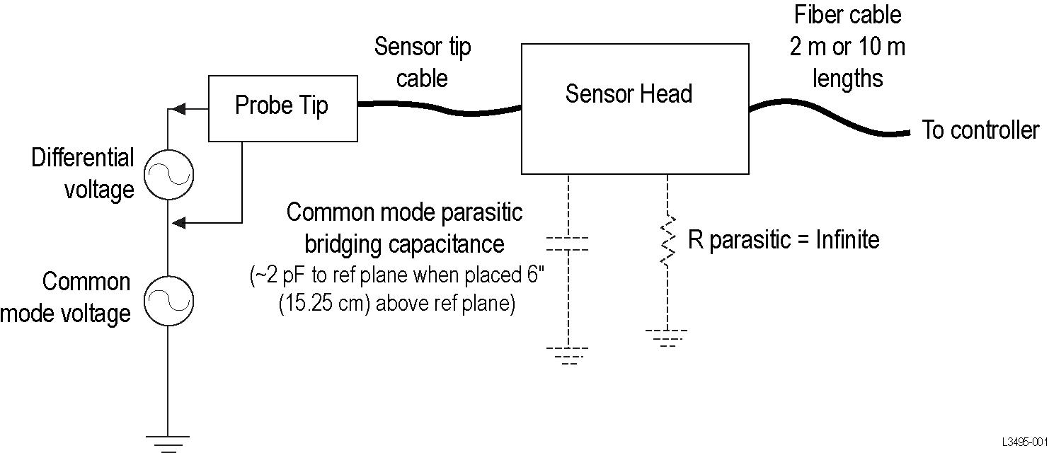
The common mode resistance and capacitance to earth ground is shown in the figure. The common mode resistance is shown as R parasitic and is essentially infinite with the IsoVu measurement system since it is galvanically isolated and can be ignored. The common mode coupling capacitance to earth ground and the surrounding circuit is shown as the Parasitic Bridging Capacitance (C parasitic). This parasitic capacitance will be approximately 2 pF when the sensor head is placed six (6) inches (15.25 cm) above a ground plane.
To minimize the effects of common mode capacitive loading consider the following items:
-
Whenever possible, choose a reference point in the circuit-under-test that is static potential with respect to earth ground.
-
Connect the coaxial (common) shield of the sensor tip cable to the lowest impedance point of the circuit.
-
Increasing the physical distance between the sensor head and any conductive surface will reduce the parasitic capacitance.
-
When using multiple IsoVu systems to measure different points in the circuit that do not have the same common mode voltages, keep the sensor heads separated to minimize the capacitive coupling.
Performance verification procedures
Use the following procedures to verify the performance of the IsoVu measurement system. Before beginning the procedures, photocopy the test record and use it to record the performance results. Test record
Required equipment
The equipment required to perform the performance verification procedures are shown in the following table.
| Description | Minimum requirements | Example product |
|---|---|---|
|
Supported oscilloscope with TekVPI interface | 50 Ω input support, fully compatible with TekVPI interface | Tektronix 5 Series MSO |
| SMA male short circuit connector cap (optional) | Internally shorted, copper plated contact | Fairview Microwave SC2135 |
Preparation
Prepare the equipment as follows:
-
Turn on the TekVPI oscilloscope.
- Connect the TIVP probe to the oscilloscope on CH 1.
- Remove any TIVP probe tip, if attached
- Attach SMA Male short circuit cap (optional)
-
Allow the test equipment to warm up for 30 minutes at an ambient temperature of about 20 °C.
System RMS Noise
This procedure verifies that the TIVP Series IsoVu measurement system is functioning and meets the warranted noise specification. The noise will be measured with no input signal at the most sensitive range.
| Note:This procedure is valid for all versions of the TIVP Series IsoVu measurement systems |
Setup the Measurement System
Procedure
Perform the measurement
Procedure
- Press the Single / Seq button.
- After 50 acquisitions, record the AC RMS measurement result in the test record table.
Test record
Use the test record table for recording the results of the performance verification procedures.
|
Model number:
Serial number:
|
Procedure performed by:
Date:
| ||
| System RMS noise performance check | |||
|---|---|---|---|
|
Probe |
Range |
Limit |
Test result |
| TIVP1 | 20 mV | 1 mV RMS | |
| TIVP05 | 20 mV | 0.7 mV RMS | |
| TIVP02 | 20 mV | 0.4 mV RMS | |
Maintenance
Information to isolate possible failures and procedures for maintaining your probe.
Service offerings
Tektronix provides service to cover repair under warranty and other services that are designed to meet your specific service needs.
Whether providing warranty repair service or any of the other services listed below, Tektronix service technicians are well equipped to service the IsoVu measurement system. Services are provided at Tektronix Service Centers and on-site at your facility, depending on your location.
Warranty repair service
Tektronix warrants this product as described in the warranty statements at the front of this manual. Tektronix technicians provide warranty service at most Tektronix service locations worldwide. The Tektronix Web site provides information on all service locations worldwide.
Calibration and repair service
In addition to warranty repair, Tektronix Service offers calibration and other services that provide cost-effective solutions to your service needs and quality standards compliance requirements. Tektronix instruments are supported worldwide by the leading-edge design, manufacturing, and service resources of Tektronix to provide the best possible service.
Cleaning
| CAUTION:To prevent damage to the measurement system, do not expose it to sprays, liquids, or solvents. Avoid getting moisture inside the comp box or sensor head when cleaning the exterior. |
Clean the exterior surfaces with a dry, lint-free cloth or a soft-bristle brush. If dirt remains, use a soft cloth or swab dampened with a 75% isopropyl alcohol solution. Use only enough solution to dampen the cloth or swab. Do not use abrasive compounds on any part of the instrument.
Troubleshooting and error conditions
The following tables describes the state of each LED and lists possible problems that you might encounter when taking measurements with a TIVP Series isolated probe. Use the tables as a quick troubleshooting reference before contacting Tektronix for service.
| LED | Status | Action | |
|---|---|---|---|
 | Green (Solid) | Normal operation | - |
 | Green (Blinking) | Bulk power failure | Try unplugging and plugging back in. Inspect probe/scope interface. Service of probe may be required. |
 | Red (Solid) | Probe application failure | Try unplugging and plugging back in. Service of probe may be required. |
 | Red (Blinking) | Probe application failure and bulk power failure | Try unplugging and plugging back in. Inspect probe/scope interface. Service of probe and/or scope may be required. |
| Red (Blinking • • – ) | Self-Test failure No Power to probe head | Try unplugging and plugging back in. Service of probe may be required. |
| LED | Status | |
|---|---|---|
| Green (Solid) | Self-calibration completed successfully |
 | Amber (Intermittent flashing) | Self-calibration currently in progress |
| Red (Solid) | Self-calibration failed |
 | Amber (Solid) |
Self-calibration recommended Internal probe temperatures or other settings have invalidated the previous Self Cal. |
| LED | Status | |
|---|---|---|
| 50 Ω | Sensor head SMA connector is terminated in 50 Ω ±5 V input range |
| 1 MΩ | Sensor head SMA connector is terminated in 1 MΩ ±5 V input range |
| Neither | Sensor head has tip attached (switching input termination disabled) | |
| LED | Status | |
|---|---|---|
 | Magenta (Flashing) | The probe compensation box is near its maximum operating temperature. Additional cooling, such as an external fan, may be required. |
|
Problem |
Remedy | ||
|---|---|---|---|
| DC offset is present in signal |
| ||
| The Square Wave edge appears “smoothed”, rolled off, or uncompensated |
| ||
| The measured amplitude is smaller than expected |
| ||
| DC measurement inaccuracy |
| ||
| There is too much noise and you cannot accurately measure small signals |
| ||
| There is no signal detected; the waveform is a flat line |
| ||
| The probe head loses power intermittently |
| ||
| There is too much common mode noise |
| ||
Repack the measurement system for shipment
If you need to return the measurement system to Tektronix for repair, use the original packaging. If this is unavailable or not fit for use, contact your Tektronix representative to obtain new packaging.
When you return the measurement system to Tektronix, attach a tag showing the following information:
-
Name of the product owner
-
Address of the owner
-
Instrument serial number
-
A description of problems encountered and/or service required
Remote programming
This sections describes commands and queries that can be sent to the sensor head when attached to a Tektronix oscilloscope. Long-form and short-form keywords are indicated with upper/lower case letters. The commands and queries are supported by most oscilloscopes; differences in supporting oscilloscopes, if any, are described with the commands.
For additional information, refer to the programmer documentation for your oscilloscope.
Command list
The commands and queries are supported by most oscilloscopes; differences in supporting oscilloscopes, if any, are described with the commands. For additional information, refer to the programmer documentation for your oscilloscope.
CH<x>:PRObe? (Query Only)
This query-only command returns all information concerning the probe that is attached to the specified channel. The channel is specified by x.
- Syntax
CH<x>:PRObe?- Examples
CH2:PROBE?might return1.0000E-01; RESISTANCE 1.0000E+07;UNITS "V";ID:TYPE "10X"'SERNUMBER "N/A"for a 10X probe, indicating that (among other parameters) the attenuation factor for the probe attached to Channel 2 is 100.0 mV (assuming that probe units are set to volts).
CH<x>:PRObe:AUTOZero (No Query Form)
This command executes the AutoZero function. The operation is entirely performed by the oscilloscope. The channel is specified by x.
Refer to the self-calibration procedure for information on performing the self calibration. Self-calibration
- Syntax
CH<x>:PRObe:AUTOZero EXECute- Arguments
EXECutesets the probe attached to the specified channel to AutoZero.- Examples
CH1:PROBE:AUTOZERO EXECUTEsets the probe attached to the Channel 1 to autozero.
CH<x>:PRObe:FORCEDRange
The command selects the dynamic range of probe (1 of 9) in +/-V. It is dependent on the attached probe tip. The channel is specified by x. The command should only be used when CH<x>:PROBECONTROL is set to MANUAL.
| Probe tip cable | Dynamic Range +/-V |
|---|---|
| No tip or 1X tip | 0.02 | 0.04 | 0.08 | 0.16 | 0.32 | 0.64 | 1.28 | 2.56 | 5.0 |
| 10X | 0.2 | 0.4 | 0.8 | 1.6 | 3.2 | 6.4 | 12.8 | 25.6 | 50.0 |
| 50X | 1.0 | 2.0 | 4.0 | 8.0 | 16.0 | 32.0 | 64.0 | 128.0 | 250.0 |
| 100X | 2.0 | 4.0 | 8.0 | 16.0 | 32.0 | 64.0 | 128.0 | 256.0 | 500.0 |
| 500X | 10.0 | 20.0 | 40.0 | 80.0 | 160.0 | 320.0 | 640.0 | 1280.0 | 2500.0 |
The query returns the dynamic range of the probe tip in +/-V.
- Syntax
CH2:PRObe:FORCEDRange <NR3>- Arguments
<NR3>specifies the probe dynamic range- Examples
-
If a current probe is attached to the Channel 1 input,
CH1:PROBE:FORCEDRANGE 5.0sets the attached probe to its 5 V range.CH3:PROBE:FORCEDRANGE?might return5.0000, indicating that the range of the probe attached to the Channel 3 is set to 5 V.
CH<x>:PRObe:GAIN? (Query Only)
The command returns the gain factor of the currently selected range (inverse of attenuation). The channel is specified by x.
- Syntax
CH<x>:PRObe:GAIN?- Examples
CH2:PROBE:GAIN?might return100.0000E-3, indicating that the attached 10X probe delivers 0.1 V to the Channel 2 BNC for every 1.0 V applied to the probe input.
CH<x>:PRObe:ID? (Query Only)
This query-only command returns the type and serial number of the probe that is attached to the specified channel. The channel is specified by x.
- Syntax
CH<x>:PRObe:ID?- Examples
CH2:PROBE:ID?might return"B010289";"TIVP1", indicating that a TIVP1 probe with serial number B010289 is attached to Channel 2.
CH<x>:PRObe:ID:SERnumber? (Query Only)
This query-only command returns the serial number of the probe that is attached to the specified channel. The channel is specified by x.
| Note:For Level 0 and 1 probes, the serial number will be “N/A”. |
- Syntax
CH<x>:PRObe:ID:SERnumber?- Examples
CH1:PROBE:ID:SERNUMBER?might return"B010289", indicating that the serial number of the probe attached to Channel 1 is B010289.
CH<x>:PRObe:ID:TYPe? (Query Only)
This query-only command returns the type of probe that is attached to the specified channel. The channel is specified by x.
- Syntax
CH<x>:PRObe:ID:TYPe?- Examples
CH1:PROBE:ID:TYPE?might return"TIVP1", indicating that a TIVP1 current probe is attached to Channel 1.
CH<x>:PRObe:RESistance? (Query Only)
This query-only command returns the resistance of the probe that is attached to the specified channel. The channel is specified by x.
- Syntax
CH<x>:PRObe:RESistance?- Examples
CH2:PROBE:RESISTANCE?might return10.00000E+6, indicating that the input resistance of the probe attached to Channel 2 is 10 MΩ. This query only returns valid data when a tip is attached. Otherwise, -1.0000 is returned.
CH<x>:PRObe:SELFCal:State? (Query Only)
This query-only command returns the self-calibration state of RECOMMENDED, RUNNING, or PASSED. The channel is specified by x.
- Syntax
CH<x>:PRObe:SELFCal:State?- Examples
CH1:PRObe:SELFCal:State?might returnRUNNING, indicating that the Channel 1 probe is currently running a self-calibration.
CH<x>:PRObe:SELFCal
This query-only command initiates self-calibration on the probe. The channel is specified by x.
- Syntax
CH<x>:PRObe:SELFCal EXECUTE- Examples
CH1:PRObe:SELFCal EXECUTEruns self-calibration on the Channel 1 probe.
CH<x>:PRObe:SET
This command sets or queries the probe input resistance for the specified channel. The channel is specified by x.
- Syntax
CH<x>:PRObe:SET {"50ohms ON"|"50ohms OFF"}- Arguments
- The text in quotes is not case sensitive. For returns, the case is the same as the last command received.
- Examples
CH6:PRObe:SET "50ohms ON"sets the input termination of channel 6 to 50 Ω.
CH<x>:PRObe:STATus? (Query Only)
This command queries the probe unsigned integer error value. The channel is specified by x.
- Conditions
- Requires a probe that supports the relevant error messages.
- Syntax
CH<x>:PRObe:STATus?- Returns
- Returns an integer number that represents the sum total of binary error bits B0 – B15. The error bits are not displayed; they are concatenated into the integer value. The following is a list of the error for each bit.
- B0 – Probe disabled
- B1 – Jaws open
- B2 – Over range
- B3 – Probe temperature out of limits
- B4 – Degauss needed
- B5 – Probe tip missing
- B6 – Probe tip failed
- B7 – Probe tip not supported
- B8 – self-calibration is needed or recommended (the query will return 256 in decimal format)
- B9 through B15 – Reserved
- Examples
CH4:PROBE:STATus?might return2, indicating that the probe is reporting an open jaws error.
CH<x>:PRObe:UNIts? (Query Only)
This query-only command returns a string describing the units of measure for the probe attached to the specified channel. The channel is specified by x.
- Syntax
CH<x>:PRObe:UNIts?- Examples
CH4:PROBE:UNITS?might return"V", indicating that the unit of measure for the probe attached to Channel 4 is Volts.
CH<x>:PROBECOntrol
This command sets or queries multirange probe range-control policy preference of the probe that is attached to CH<x>. The channel number is specified by x.
- Syntax
CH<x>:PROBECOntrol {AUTO|MANual}- Arguments
AUTOsets the values. The probe range is automatically calculated.- Examples
-
CH2:PROBECONTROL AUTOsets the values and the probe range is automatically calculated.
CH<x>:PROBEFunc:EXTAtten
This command is used to specify the attenuation value as a multiplier to the given scale factor on the specified channel. The channel is specified by x.
The query form of this command returns the user-specified attenuation.
- Syntax
CH<x>:PROBEFunc:EXTAtten <NR3>- Arguments
<NR3>is the attenuation value, which is specified as a multiplier in the range from 1.00E-10 to 1.00E+10.- Examples
CH1:PROBEFUNC:EXTATTEN 167.00E-3specifies an external attenuation, which is connected between the your input signal and the input of the probe attached to Channel 1.
CH<x>:PROBEFunc:EXTDBatten
This command sets or queries the input-output ratio (expressed in decibel units) of external attenuation or gain between the signal and the instrument input channels. The channel is specified by x.
The query form of this command returns the user-specified attenuation in decibels.
- Syntax
CH<x>:PROBEFunc:EXTDBatten <NR3>- Arguments
<NR3>is the attenuation value, which is specified in the range from -200.00 dB to 200.00 dB.- Examples
CH3:PROBEFUNC:EXTDBATTEN 2.5specifies an external 2.5 dB attenuator on Channel 3.
CH<x>:PROBEFunc:EXTUnits
This command sets the unit of measurement for the external attenuator of the specified channel. The channel is specified by x. The alternate units are used if they are enabled. Use the CH<x>:PROBEFunc:EXTUnits:STATE command to enable or disable the alternate units.
- Syntax
CH<x>:PROBEFunc:EXTUnits <QString>- Arguments
<QString>indicates the attenuation unit of measurement for the specified channel.- Examples
CH4:PROBEFUNC:EXTUNITS "Pascals"sets the unit of measurement for the Channel 4 external attenuator.
CH<x>:PROBEFunc:EXTUnits:STATE
This command sets or queries the custom units enable state for the specified channel. The channel is specified by x.
- Syntax
CH<x>:PROBEFunc:EXTUnits:STATE {ON|OFF|<NR1>}- Arguments
OFFargument turns off external units.- Examples
CH2:PROBEFunc:EXTUnits:STATE ONturns on external units.
CH<x>:PROBE:DYNAMICRANGE? (Query Only)
This command queries the dynamic range of the probe that is attached to the specified channel. The channel is specified by x.
- Syntax
CH<x>:PROBE:DYNAMICRANGE?- Returns
- The returned value is the delta between the current minimum and maximum range with some tolerance. It is also the delta between the probe range indicators (if currently displayed).
- Examples
CH1:PROBE:DYNAMICRANGE?might return1.3056, indicating that the dynamic range of the probe attached to the Channel 1 is set to 1.3056 V.
Help us improve our technical documentation. Provide feedback on our TekTalk documentation forum.