
THIS APPLICATION NOTE
- Gives a brief orientation on the physical layer and packet structures of SENT, with a goal of providing just enough detail to help with troubleshooting
- Explains how to set up decoding on an oscilloscope equipped with SENT decoding
- Explains how to interpret fast and slow channel packet data on an oscilloscope equipped with SENT decoding
- Explains what triggering and searching options are available on an oscilloscope equipped with SENT serial triggering and analysis
With the optional serial triggering and analysis capability, Tektronix oscilloscopes become powerful tools for embedded system designers working with SENT buses. In this application note the 5 Series MSO is used to demonstrate SENT serial bus decoding and triggering.
Tektronix 2 Series MSO, 4 Series MSO, 5 Series MSO, and 6 Series MSO oscilloscopes support SENT triggering and analysis. The operation of all of these instruments is practically identical to the 5 Series MSO used in this application note. See the Oscilloscope Selection Guide for more information.
Introduction
Increasingly, automotive designs are adopting Single Edge Nibble Transmission (SENT) protocol for low-cost, asynchronous, point-topoint transmission of high-resolution data.
SENT buses are well-defined and are designed to be robust and easy to integrate, but communications can be affected by noise, board layout, reset issues, and subtle differences in implementations. These can sometimes result in bus errors and system malfunctions.
Unlike basic protocol analyzers, oscilloscopes equipped with protocol decoding, can be used to see both the decoded bus traffic, as well as signal quality. This ability to see bus signals and decoded traffic makes oscilloscopes the best choice for visualizing overall system operation. Perhaps more importantly, oscilloscopes can be used to troubleshoot problems at the system level. Automobiles rely on extensive networks of sensors, actuators and displays, and many problems involve bus timing relative to I/O events or values. Oscilloscopes are well-suited for looking at I/O signals and bus transactions at the same instant. Because of this capability, they are the instrument of choice for system-level debugging.
SENT
Also known as SAE J2716, SENT is used for communication between power-train sensors and Electronic Control Units (ECUs). SENT provides higher precision than analog PWM techniques and, at 30 kb/s, it has a higher data rate than LIN.
HOW IT WORKS
A typical SENT transmission looks like this:
The physical layer of the SENT interface consists of a signal line, a +5V supply voltage line, and a ground. The signal line logic levels are low < 0.5V and high > 4.1V.
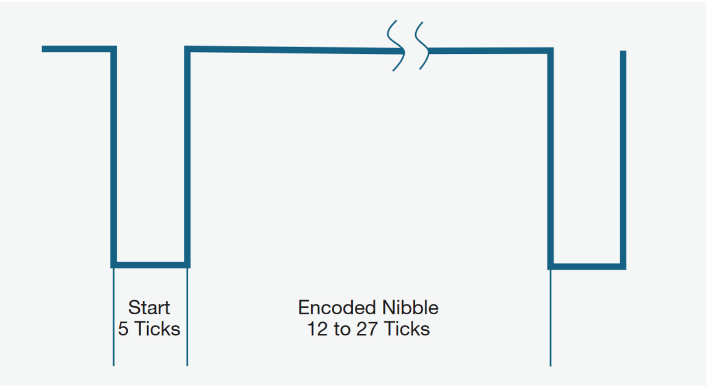
SENT transmits data in 4-bit nibbles between two falling edges, hence the name "Single Edge Nibble". Timing of the SENT bus is measured in ticks, with each tick typically 3 μs wide. Each nibble starts with a logic-low period of at least 5 ticks, followed by a variable-length logic-high period representing the encoded data value. A 0000 binary data value is represented by a logic-high duration of 12 ticks. A 0001 binary data value is represented by a logic-high duration of 13 ticks, and so on, up to a 1111 binary data value is represented by a logic-high duration of 27 ticks.
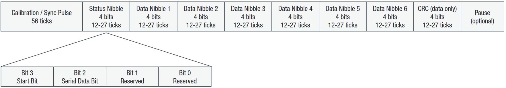
The SENT "fast channel" message begins with a sync pulse where the time between successive falling edges is 56 clock ticks. The SENT message is 32 bits long, consisting of:
- 4 bits of status / communication information (12-27 ticks)
- six, 4-bit nibbles of data (representing one or two measurement channels, 12-27 ticks per nibble)
- 4 bits of CRC for error detection (12-27 ticks)
Optionally, a 20-bit message (where the 12 data bits represent one measurement channel) can be sent, followed by a pause pulse, resulting in the same overall message rate.
For example, when two 12-bit fast channels are used, the transmission looks like this:

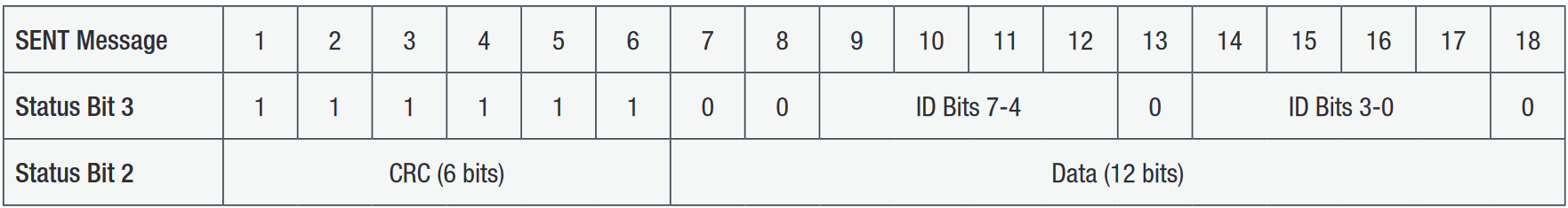
The SENT standard also supports “slow channel” messages, where data is transmitted 1-2 bits at a time via bits 2 and 3 of the 4-bit status / serial communication nibble in 16 or 18 successive fast channel messages. These bits are accumulated to build the slow channel message.
For example, the “Enhanced Serial Message with 12-bit Data and 8-bit ID Format” is identified by the initial bit pattern “11111100” and transmits an 8-bit ID value, a 6-bit CRC, and a 12-bit data value:
SETTING UP SENT BUS DECODING
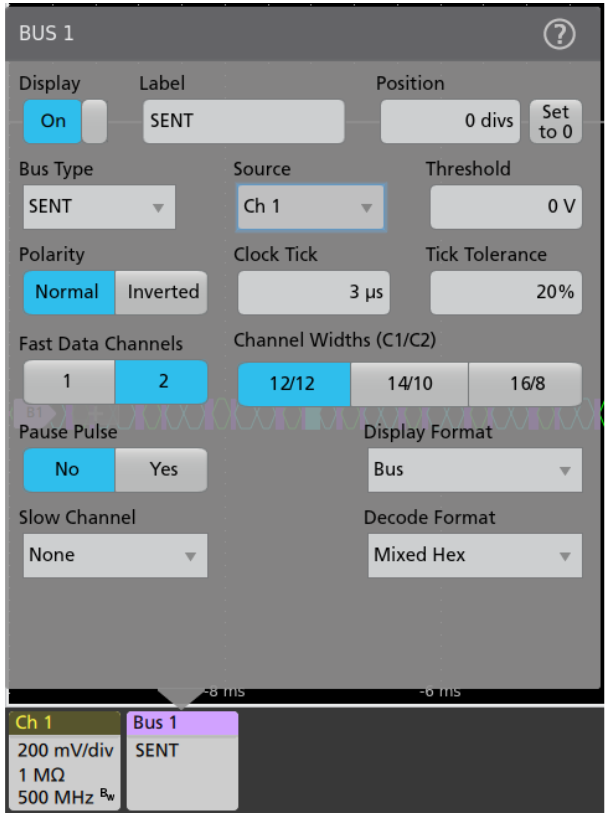
On Tektronix oscilloscopes equipped with SENT decoding and triggering, pressing the front panel Bus button enables you to define inputs to the scope as a bus. To enable the oscilloscope to decode the packet data, you enter some basic parameters, including:
- Input channel
- Voltage threshold
- Signal polarity
- Number of fast channels and channel format
- Number of slow channels and channel format
- Pause pulse
The SENT bus is a single-ended, ground-reference signal. Although the oscilloscope can acquire and decode the bus using standard single-ended probing, the signal fidelity and noise immunity may be improved by using differential probing
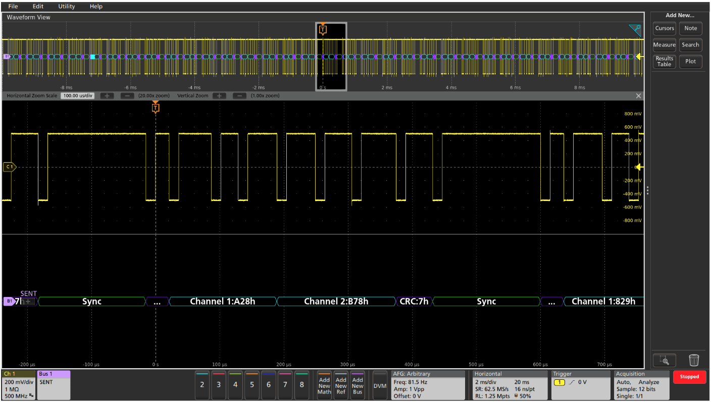
INTERPRETING THE SENT BUS
The time-correlated waveform and bus decode display is a familiar and useful format for many hardware engineers. The decoded bus waveform indicates the elements of a SENT fast-channel message.
| SENT FAST CHANNEL BUS ELEMENT | INDICATED BY |
| Sync (56 ticks wide) |
 |
| Status |
 |
| Data |
 |
| CRC |
 |
| Pause |
 |
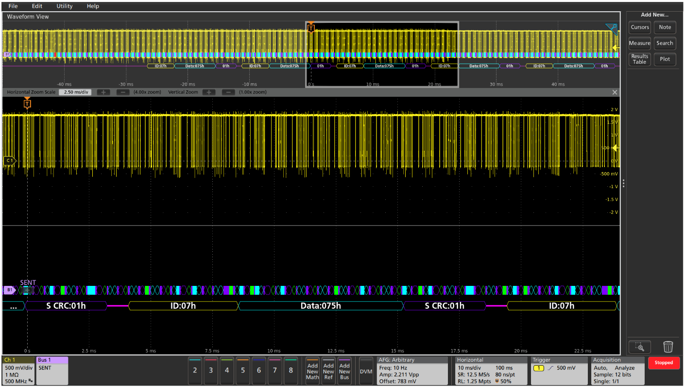
The decoded SENT bus can display both fast and slow channel packets in a single waveform display, with the slow channel packets shown below the fast channel packets.
| SENT SLOW CHANNEL BUS ELEMENT | INDICATED BY |
| Identifier |
 |
| Data |
 |
| CRC |
 |
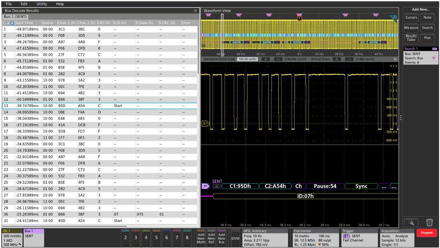
For firmware engineers, the Results Table format may be more useful. This time-stamped display of bus activity can be easily compared to software listings, and allows easy calculation of the execution speed.
When the SENT bus contains both fast and slow channel data, the Results Table provides sideby-side readouts of the two data channels. Notice that, since the slow channel data is spread across 18 successive fast channel packets, there are 18 fast channel messages from the start to the completion of the slow channel data message.
The Results Table also provides linkage back to the waveform displays. You can tap a line in the tabular display and the oscilloscope automatically zooms in on the corresponding bus signals and resulting decoded bus waveform, shown in the lower section of the screen.

TRIGGERING ON THE SENT BUS
When debugging a system based on one or more serial buses, one of the key capabilities of the oscilloscope is isolating and capturing specific events with a bus trigger. When the bus trigger is correctly set up, the oscilloscope will capture all the input signals and one specified bus event will be positioned at the trigger point. This example demonstrates triggering on status value of 0000 binary, fast channel 1 data value 0x27F, and fast channel 2 data value 0xC72.
| TRIGGER ON | DESCRIPTION |
| Start of Packet | Triggers when sync pulse is detected. |
| Fast Channel | Triggers when the specified status/communication bit pattern and the specified fast channel data value(s) occur. |
| Slow Channel | Triggers when the specified message ID bit pattern and the specified slow channel data value occur. |
| Error | Triggers whenever incorrect CRC values occur. |
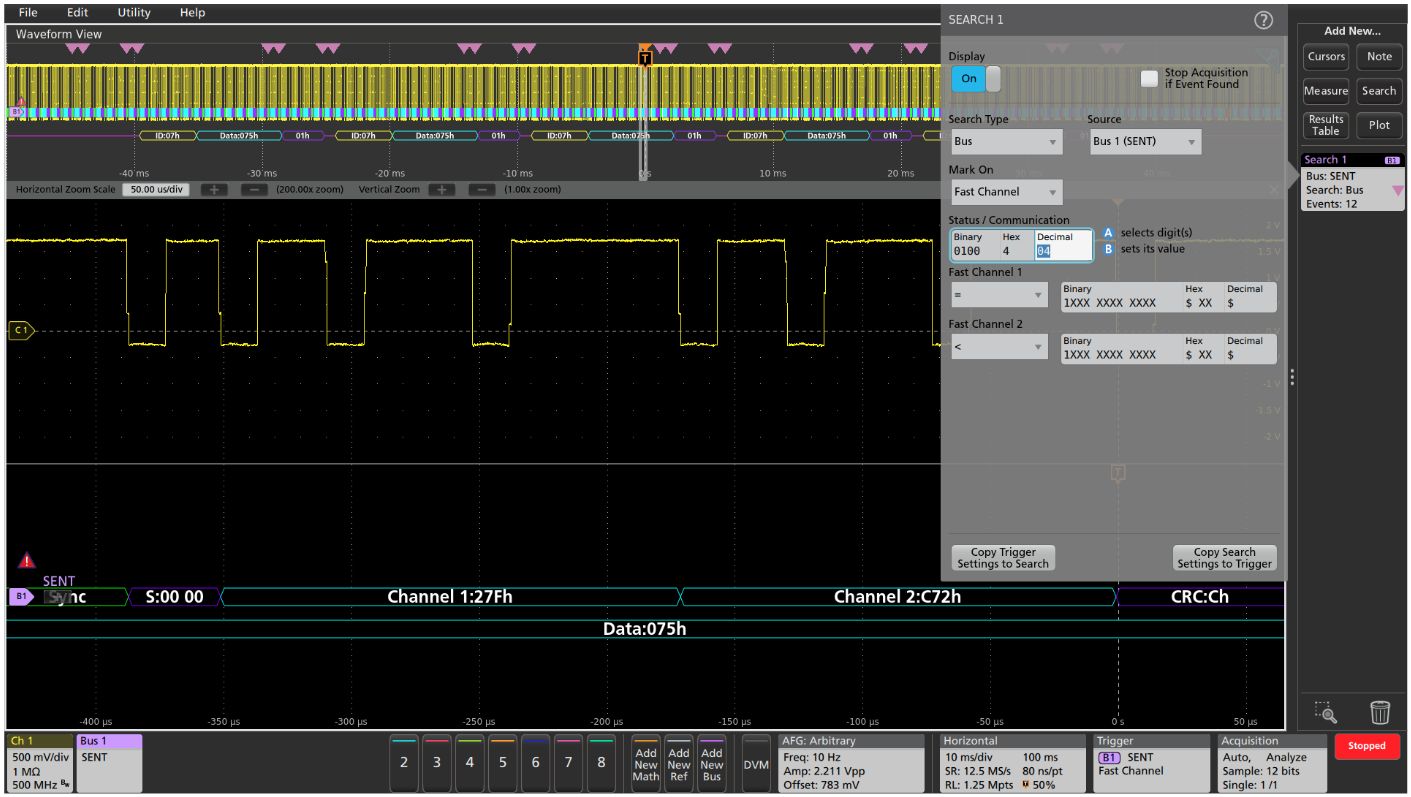
SEARCHING THE SENT BUS
On a Tektronix oscilloscope, you can use the automated Wave Inspector search to find all the bus events that meet search criteria and determine how many of them occurred. The setup is similar to the bus trigger setup, and allows the oscilloscope to find and mark all of the specified bus events. In this example, the automatic search is looking for specified fast channel data values. This data pattern occurs 12 times in the acquired waveforms and the positions of the specified serial data packets are shown with the pink bracket icons.
| SEARCH ON | DESCRIPTION |
| Start of Packet | Marks when sync pulse is detected. |
| Fast Channel | Marks when the specified status/communication bit pattern and the specified fast channel data value(s) occur. |
| Slow Channel | Marks when the specified message ID and the specified slow channel data value occur. |
| Pause Pulse | Marks when a pause pulse of the specified duration occurs. |
| Error | Marks whenever an incorrect frame length or incorrect CRC value occurs. |
Find more valuable resources at TEK.COM
Copyright © Tektronix. All rights reserved. Tektronix products are covered by U.S. and foreign patents, issued and pending. Information in this publication supersedes that in all previously published material. Specification and price change privileges reserved. TEKTRONIX and TEK are registered trademarks of Tektronix, Inc. All other trade names referenced are the service marks, trademarks or registered trademarks of their respective companies.
01/24 55W-61326-2