
Свяжитесь с нами
Живой чат с представителями Tektronix. С 9:00 до 17:00 CET
Звонок
Позвоните нам
С 9:00 до 17:00 CET
Загрузить
Загрузить руководства, технические описания, программное обеспечение и т. д.:
Обратная связь
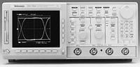
InstaVu™ Acquisition Oscilloscopes
TDS500C • TDS700C
Tektronix больше не продаёт продукты из этого технического описания.
Посмотреть бывшее в употреблении оборудование для тестирования Tektronix Encore.
Просмотреть информацию о технической поддержке и гарантии для этих продуктов.
TDS500C • TDS700C
Features & Benefits
- 1 GHz and 500 MHz Bandwidth
- Sample Rates to 4 GS/s
- Up to 400,000 Wfms/s
- Two or Four Channels
- 1% Vertical Accuracy
- 8-Bit Vertical Resolution, over 11 Bits with Averaging, and Over 13 Bits with Hi-Res
- 1 ns Peak Detect
- 1 mV to 10 V/div Sensitivity
- Up to 1 GHz Differential Measurements
- Channel Deskew
- Record Lengths to 8 M Points
- Floppy and Hard Disk Storage
- Advanced Triggering
- 29 Automatic Measurements and Measurement Statistics
- FFT and Advanced Math
- Waveform Histograms
- Limit Test
- Communication Signal Analysis Including Mask Testing and SONET/SDH and Fiber Channel Optical Reference Receivers
- Full GPIB Programmability
- Three-Year Warranty
- CE Marking
The TDS500C/TDS700C Family of Digitizing Oscilloscopes
The TDS500C/700C oscilloscopes are the latest in the TDS family of digitizing oscilloscopes designed to keep pace with current and evolving needs in advanced electronic design and debug. They are also powerful tools for communication design and R&D applications.
At over 400,000 waveforms per second, the TDS500C and TDS700C products with InstaVu™ Acquisition have the fastest waveform capture rate available on an oscilloscope. They allow you to instantly view even the rarest signal events.
Like the other members of the TDS series, the TDS500C and TDS700C products have a well-rounded combination of a graphical user interface, high-fidelity acquisition, advanced triggering, automatic measurements, and complementary measurement accessories.
EASY TO LEARN AND EASY TO USE
Extensive user interface design has made the TDS family of products truly intuitive to operate. Each family member shares a familiar front-panel layout with dedicated vertical, horizontal, and trigger controls. A graphical user interface with over 200 icons helps facilitate understanding and use of the advanced features. A color monitor helps rapidly distinguish between multiple waveforms and measurements. Online help provides a convenient built-in reference manual.
HIGH-FIDELITY SIGNAL ACQUISITION
The high waveform capture rate of the TDS500C/700C InstaVu series, together with its high bandwidth and sample rate, delivers instantaneous signal feedback to show the true signals that other scopes may be missing. InstaVu acquisition acquires waveforms over 1000 times faster than any other DSO, allowing the capture of intermittent signals, reducing debugging times from hours to seconds.
Channels can be transparently combined to achieve higher sample rates and longer record lengths. The record length can be optionally increased to 8 M points, providing a high-resolution representation of the signal over a long period of time.
All of the TDS products provide wide dynamic range, flat response, fast overdrive recovery, calibrated DC offset, 1 mV/div sensitivity, 1 ns peak detect, and internal calibration.
POWERFUL AND FLEXIBLE TRIGGERING
In addition to basic triggering such as edge and pulse-width, these TDS oscilloscopes have several trigger modes tailored for specific design and debug applications. Logic and pulse triggers, including setup/hold, glitch, slew rate, and time-out triggers, capture hard-to-catch digital design problems. The optional video trigger provides line and field selection for NTSC, PAL, and HDTV standards. The optional comm trigger addresses needs to acquire a wide variety of AMI, CMI, and NRZ communication signals.
This waveform, captured in normal DSO mode, shows a well-behaved, repetitive digital waveform.

The same waveform, captured with InstaVu acquisition, uncovers detail in the signal which goes unnoticed by a common DSO.
ADVANCED PERFORMANCE FEATURES
The TDS products use a Multiprocessor Architecture, which includes a Tektronix TriStar™ digital signal processor and a powerful proprietary display processor, to provide the power for waveform math, high-speed averaging, automatic limit testing, mask testing, live measurements, and variable persistence display.
Color-Graded Variable Persistence - Displays historical information that has been acquired over time. This is especially powerful when used in InstaVu™ mode, where the colors show relatively how often random glitches occur.
Automatic Measurements - Eliminate the need for manually measuring the waveform against the graticule or with cursors. Measurement gating allows the user to select a specific part of the live waveform for measurement. Measurement statistics (min, max, mean, and standard deviation), give additional information about the variations in the measurements over time (for example, worst case excursions), increasing the confidence in the quality of the measurements.
Advanced Waveform Processing - Provides FFT signal analysis and signal integration and differentiation.
Waveform Histograms - Allow the examination of the statistical nature of the signal. Horizontal histograms, which are useful for evaluating signal jitter, sample the waveform within a specified region, sort the values into time bins, and plot the accumulated bin values versus time. Vertical histograms, which are useful for evaluating signal noise, sample the waveform within a specified region, sort the values into amplitude bins, and plot the accumulated bin values versus amplitude.
Limit Testing - Compares acquired or math waveforms against a template "on-the-fly", stopping acquisition, saving to disk, or automatically printing the waveform whenever it violates the template.
Communication Mask Testing (available as an option) - Allows mask compliance testing of a wide variety of communication signals to industry standards. Specialized measurement accessories, unique trigger modes, built-in optical reference receiver filters, mask autoset, and mask violation counting make these measurements easily and repeatedly.

The vertical histogram of the selected region of the waveform shows the character of the noise.
Channel Deskew - Allows increased measurement accuracy by correcting interchannel timing errors up to ±25 ns introduced by propagation delays in circuit probing.
COMPLEMENTARY MEASUREMENT ACCESSORIES
Tektronix provides a wide range of measurement accessories optimized for the TDS family. These accessories are designed to operate by using the TEKPROBE® interface, which provides power and automatic scaling, to complete the TDS measurement solutions.

A SONET/SDH (OC-3/STM-1) signal is compared with the standard mask, showing a compliant waveform.
Active Probes - Designed specifically for the TDS products, such as the P6243 and P6245. For example, the P6245 is capable of achieving the full 1 GHz bandwidth on a 1 GHz TDS while providing low loading (1 pF capacitance and 1 megohm resistance). The low-mass compact design of these probes makes them ideal for hands-free probing of fine-pitch surface-mount devices.
Optical-to-Electrical Converters (P6701B, P6703B) - Allow convenient analysis of optical transmission signals with the oscilloscope. Both short- and long-wavelength optical converters are compatible with the industry-standard wavelengths for SONET/SDH and Fiber Channel.
High-Bandwidth Differential Probes (P6246, P6247) - Enable high bandwidth (up to 1 GHz) differential measurements while maintaining high common-mode rejection. The small probe head design and assorted tip accessories allow easy probing of SMDs. These probes provide low circuit loading and are ESD-rugged.
Current Probes - Allow safe, high-power measurements, such as the TCP202 and High-Voltage Differential Probes such as the P5205 and P5210. Direct Probe Readouts use information from the probes to display measurements in units of Amps, Volts, and Watts.
SOPHISTICATED DOCUMENTATION
Save screen displays in a number of standard desktop publishing formats to the internal 3.5-in. DOS-compatible floppy disk drive. Transfer the disk to a PC for import into word processing applications. Make hard copies directly to monochrome or color printers and plotters connected to the GPIB, RS-232, or Centronics ports, or acquire waveforms, screen displays, and scope settings using Tektronix WaveStar™ software running on a PC interfaced to the GPIB port.
Characteristics
TDS500C/700C SERIES ELECTRICAL CHARACTERISTICS
|
|
TDS784C |
TDS754C |
TDS724C |
TDS580C |
TDS540C |
TDS520C |
|---|---|---|---|---|---|---|
|
Bandwidth |
1 GHz*1 |
500 MHz*2 |
500 MHz*2 |
1 GHz*4 |
500 MHz*2 |
500 MHz*2 |
|
# Channels |
4 |
4 |
2 + 2 aux. |
4 |
4 |
2 + 2 aux. |
|
# Samplers |
4 |
4 |
2 |
|
4 |
2 |
|
Max Real-Time Sample Rate |
||||||
|
1 channel |
4 GS/s |
2 GS/s |
1 GS/s |
4 GS/s |
2 GS/s |
1 GS/s |
|
2 channels |
2 GS/s |
2 GS/s |
500 MS/s |
2 GS/s |
1 GS/s |
500 MS/s |
|
3-4 channels |
1 GS/s |
1 GS/s |
NA |
1 GS/s |
500 MS/s |
NA |
|
Equivalent-time Sample Rate |
250 GS/s max. |
100 GS/s max. |
100 GS/s max. |
250 GS/s max. |
100 GS/s max. |
100 GS/s max. |
|
Maximum Record Length |
||||||
|
1 channel |
50 K (Opt. 1M: 500 K, Opt. 2M: 8 M) |
50 K (Opt. 1M: 500 K, Opt. 2M: 8 M) |
50 K (Opt. 1M: 250 K, Opt. 2M: 4 M) |
50 K. Up to 8 M on one channel |
50 K (Opt. 1M: 500 K, Opt. 2M: 8 M) |
50 K (Opt. 1M: 250 K, Opt. 2M: 4 M) |
|
2 channels |
50 K (Opt. 1M: 250 K, Opt. 2M: 4 M) |
50 K (Opt. 1M: 250 K, Opt. 2M: 4 M) |
50 K (Opt. 1M: 130 K, Opt. 2M: 2 M) |
|
50 K (Opt. 1M: 250 K, Opt. 2M: 4 M) |
50 K (Opt. 1M: 130 K, Opt. 2M: 2 M) |
|
3-4 channels |
50 K (Opt. 1M: 130 K, Opt. 2M: 2 M) |
50 K (Opt. 1M: 130 K, Opt. 2M: 2 M) |
NA |
|
50 K (Opt. 1M: 130 K, Opt. 2M: 2 M) |
NA |
|
Max Sample Rate Window*3 |
2 ms |
4 ms |
4 ms |
4 ms |
4 ms |
4 ms |
|
Display |
NuColor™ |
NuColor™ |
NuColor™ |
monochrome |
monochrome |
monochrome |
*1 In 50 Ohm mode: 5 mV/div: 750 MHz, 2 mV/div: 600 MHz, 1 mV/div: 500 MHz. Reduce the upper bandwidth frequencies by 5 MHz for each °C above 30 °C.
*2 In 50 Ohm mode: 1 mV/div: 450 MHz. Reduce the upper bandwidth frequencies by 2.5 MHz for each °C above 30 °C.
*3 Single-channel operating at full sample rate and maximum record length (Opt. 2M).
*4 ≥10 mV/div in 50 Ohm mode.
TDS500C/700C SERIES VERTICAL SYSTEM
|
|
TDS784C |
TDS754C |
TDS724C |
TDS580C |
TDS540C |
TDS520C |
|---|---|---|---|---|---|---|
|
Sensitivity |
1 mV/div to 10 V/div (1 megohm mode), 1 mV/div to 1 V/div (50 Ohm mode) |
|||||
|
DC Gain Accuracy |
±1.0% (±0.7% typical) |
±1.0% (±0.7% typical) |
±1.0% (±0.7% typical) |
±1.0% |
±1.0% (±0.7% typical) |
±1.0% (±0.7% typical) |
|
Effective Bits (typical) |
5.5 (1 GHz at 4 GS/s), 9.7 with Hi-Res (1 MHz at 10 MS/s) |
6.8 (500 MHz at 2 GS/s), 9.7 with Hi-Res (1 MHz at 10 MS/s) |
6.5 (490 MHz at 1 GS/s), 9.7 with Hi-Res (1 MHz at 10 MS/s) |
|
6.8 (500 MHz at 2 GS/s), 9.7 with Hi-Res (1 MHz at 10 MS/s) |
6.5 (490 MHz at 1 GS/s), 9.7 with Hi-Res (1 MHz at 10 MS/s) |
|
Vertical Resolution |
8 bits (256 levels on 10.25 divisions), >11 bits with averaging, >13 bits typical with Hi-Res (TDS784C, TDS580C), >12 bits typical with Hi-Res (TDS754C, TDS724C, TDS540C, TDS520C) |
|||||
|
Position Range |
±5 divisions |
±5 divisions |
±5 divisions |
±5 divisions |
±5 divisions |
±5 divisions |
|
Offset Range |
±1 V from 1 mV to 100 mV/div, ±10 V from 101 mV to 1 V/div, ±100 V from 1.01 V to 10 V/div |
|||||
|
Analog Bandwidth Selections |
20 MHz, 250 MHz, full |
20 MHz, 250 MHz, full |
20 MHz, 250 MHz, full |
20 MHz, 250 MHz, full |
20 MHz, 250 MHz, full |
20 MHz, 250 MHz, full |
|
Input Coupling |
AC, DC, GND |
AC, DC, GND |
AC, DC, GND |
AC, DC, GND |
AC, DC, GND |
AC, DC, GND |
|
Input Impedance Selections |
1 megohm in parallel with 10 pF, or 50 Ohm (AC and DC coupling) |
|||||
|
AC-coupled Low Frequency Limit |
≤10 Hz when AC 1 megohm coupled. ≤200 kHz when AC 50 Ohm coupled |
|||||
|
Channel Isolation |
>100:1 at 100 MHz and >30:1 at the rated bandwidth for any 2 channels having equal V/div settings |
|||||
|
Max. Input Voltage |
300 V CAT II ±400 V (peak). Derate at 20 dB/decade above 1 MHz. 1 megohm or GND coupled |
300 V CAT II ±400 V (peak). Derate at 20 dB/decade above 1 MHz. 1 megohm or GND coupled |
300 V CAT II ±400 V (peak). Derate at 20 dB/decade above 1 MHz. 1 megohm or GND coupled |
±400 V (DC + peak AC). Derated at 20 dB/decade above 1 MHz, 1 megohm or GND coupled |
300 V CAT II ±400 V (peak). Derate at 20 dB/decade above 1 MHz. 1 megohm or GND coupled |
300 V CAT II ±400 V (peak). Derate at 20 dB/decade above 1 MHz. 1 megohm or GND coupled |
TDS500C/700C SERIES TIMEBASE SYSTEM
|
|
TDS784C / TDS580C |
TDS754C / TDS724C / TDS540C / TDS520C |
|---|---|---|
|
Time Bases |
Main, delayed |
Main, delayed |
|
Time Base Range |
200 ps to 10 s/div |
500 ps to 10 s/div |
|
Time Base Accuracy |
±25 ppm (over any interval ≥1 ms) |
|
|
Pretrigger Position |
0% to 100% of any record |
|
|
Delay Between Channels |
≤50 ps (any 2 channels with equal V/div and coupling) |
|
ACQUISITION MODES
InstaVu - Instantaneous capture of random glitches and changing signals. Captures over 400,000 waveforms per second (TDS784C, TDS754C, TDS580C, and TDS540C) or 180,000 wfms/s (TDS724C and TDS520C). Uses color grading (TDS700Cs) to show relative occurrence of events.
Peak Detect - High-frequency and random-glitch capture. Captures glitches of 1 ns using acquisition hardware at all real-time sampling rates.
Sample - Sample data only.
Envelope - Max/min values acquired over one or more acquisitions.
Average - Waveform data from 2 to 10,000 (selectable) is averaged.
Hi-Res - Vertical-resolution improvement and noise reduction on low-frequency signal (e.g., 13 bits typical for the TDS784C at 50 ms/div and slower, 12 bits typical for the other TDS700C/500C instruments).
FastFrame™ - Acquisition memory size segmentable with trigger rate up to 50,000 per second from 50 to 5,000 points per frame (independent of the number of channels).
Single Sequence - Use RUN/STOP button to capture a single triggered acquisition at a time, which may be automatically saved to NVRAM with AutoSave.
TRIGGER SYSTEM
Triggers - Main and delayed.
Main Trigger Modes - Auto, Normal, Single.
Delayed Trigger - Delayed by time, events, or events and time.
Time Delay Range - 16 ns to 250 s.
Events Delay Range - 1 to 9,999,999 events.
External Rear Input - ≥1.5 kW ; Max input voltage is ±20 V (DC + peak AC).
TRIGGER TYPES
EDGE (Main and Delayed) - Conventional level-driven trigger. Positive or negative slope on any channel or rear-panel auxiliary input. Coupling selections: DC, AC, noise reject, HF reject, LF reject.
LOGIC (Main) -
PATTERN: Specifies a logical combination (AND, OR, NAND, NOR) of the four input channels (high, low, don't care). Trigger when pattern stays true or false for a specified time.
STATE: Any logical pattern of channels 1, 2, and 3 (AUX1 on 2-CH products) plus a clock edge on channel 4 (AUX2 on 2-CH products). Triggerable on rising or falling clock edge.
SETUP/HOLD: Trigger on violations of both setup time and hold time between clock and data which are on two input channels.
PULSE (Main) -
GLITCH: Trigger on or reject glitches of positive, negative, or either polarity. Minimum glitch width is 1.0 ns with 200 ps resolution.
RUNT: Trigger on a pulse that crosses one threshold but fails to cross a second threshold before crossing the first again.
WIDTH: Trigger on width of positive or negative pulse either within or out of selectable time limits (1 ns to 1 s).
SLEW RATE: Trigger on pulse edge rates that are either faster or slower than a set rate. Edges can be rising, falling, or either.
TIMEOUT: Trigger on an event which remains high, low, or either, for a specified time period, selectable from 1 ns to 1 s, with 200 ps resolution.
COMM (Optional) -
AMI: Trigger on standard communications signals (including DS1, DS1A, DS1C, DS2, DS3, E1, E2, E3, STS-1, or a custom bit rate). Select between "isolated ones" (positive or negative) and eye diagrams.
CMI: Trigger on standard communications signals (including STS-3, STM1E, DS4NA, E4, or a custom bit rate). Select between positive or negative one pulses, zero pulses, and eye diagrams.
NRZ: Trigger on standard communications signals (including OC1/STM0, OC3/STM1, OC12/STM4, E5, FC133, FC266, FC531, FC1063, FDDI HALT, 143 Mb/s serial digital composite video, 270 Mb/s serial digital component video, or a custom bit rate). Select between an eye diagram, rising or falling edges, or any of eight 3-bit serial patterns.
VIDEO (Optional) - Trigger on a particular line of individual, odd/even, or all fields. Trigger on a specific pixel of a line by using the video trigger with delay by events. Choose positive or negative horizontal-sync polarity.
525/NTSC: Choose monochrome or color (studio-quality NTSC) sync formats.625/PAL: Choose color or monochrome (studio-quality PAL) sync formats.HDTV: Choose from 1125/60, 1050/60, 1250/50, and 787.5/60 HDTV formats.
FlexFormat™ - Define HDTV-type formats by defining frame rep rate, numbers of lines and fields, and vertical-sync timing structure.
MEASUREMENT SYSTEM
Automatic Waveform Measurements - Period, frequency, +width, -width, rise time, fall time, +duty cycle, -duty cycle, delay, phase, burst width, high, low, max. min, peak to peak, amplitude, +overshoot, -overshoot, mean, cycle mean, RMS, cycle RMS, area, cycle area, extinction ratio (ratio, dB, %), and mean optical power. Continuous update of up to four measurements on any combination of waveforms.
Time Measurement Accuracy - (single-shot, typical) <38 ps at 4 GS/s (TDS784C), <80 ps at 2 GS/s (TDS754C, TDS540C), <150 ps at 1 GS/s (TDS724C, TDS520C)
Measurement Statistics - Display minimum and maximum or mean and standard deviation on any displayed single-waveform measurements.
Thresholds - Settable in percentage or voltage.
Gating - Any region of the waveform may be isolated for measurement using vertical bars.
Snapshot - Performs all measurements on any one waveform showing results from one instant in time.
Cursor Measurements - Absolute, Delta: Volts, Time, Frequency, and NTSC IRE and line number (with video trigger option).
Cursor Types - Horizontal bars (volts), vertical bars (time); operated independently or in tracking mode.
WAVEFORM PROCESSING
Waveform Functions - Sin(x)/x or linear interpolation, Average, Envelope.
Advanced Waveform Functions (optional on TDS500C) - FFT, Integration, Differentiation.
Arithmetic Operators - Add, Subtract, Multiply, Divide, Invert.
Autoset - Single-button, automatic setup on selected input signal for vertical, horizontal, and trigger systems. Also automatically normalizes signals to standard masks when used with the mask testing option.
Waveform Limit Testing - Compares incoming or math waveform to a reference waveform's upper and lower limits.
Waveform Histograms - Both vertical and horizontal histograms, with periodically updated measurements, allow statistical distributions to be analyzed over any region of the signal.
Mask Testing (Optional) - In addition to the standard communication masks in the instrument, the masks can be edited on the screen. Together with automatic waveform scaling, the mask tests give rapid verification of a digital bit stream's conformance to pulse templates and eye pattern masks. For optical conformance testing, the internal Fiber Channel and SONET/SDH optical reference receiver filters provide convenient test setup which is compliant to industry standards.
ZOOM CHARACTERISTICS
The zoom feature allows waveforms to be expanded or compressed in both vertical and horizontal axes. Allows precise comparison and study of fine waveform detail without affecting ongoing acquisitions. When used with Hi-Res or Average acquisition modes, Zoom provides an effective vertical dynamic range or 1000 divisions or 100 screens.
Dual Window Zoom - Dual graticules simultaneously show selected and zoomed waveforms. Up to two zoom boxes show areas on the selected trace that are being magnified, and the two magnified areas can be overlapped for quick comparison. Color of zoomed trace matches selected trace.
DISPLAY CHARACTERISTICS
Waveform Style - Dots, vectors, variable persistence from 32 ms to 10 s, infinite persistence, and intensified samples.
Color (TDS784C, TDS754C, TDS724C) - Standard palettes and user-definable color for waveforms, text, graticules, and cursors. Measurement text and cursor colors matched to waveform. Waveform collision areas highlighted with different color. Statistical waveform distribution shown with color grading through variable persistence.
Color Grading (TDS784C, TDS754C, TDS724C) - With variable persistence selected, historical timing information is represented by temperature or spectral color scheme providing "z-axis" information about rapidly-changing waveforms.
Gray Scaling (TDS580C, TDS540C, TDS520C) - With variable persistence selected, waveform points time-decay through 16 levels of intensity.
Waveform Capture Rate - For 500-point waveforms with infinite persistence mode selected: typically 150 wfms/s (TDS700C and TDS500C). With InstaVu™ on: >400,000 wfms/s (TDS784C, TDS754C, TDS580C, TDS540C) and >180,000 wfms/s (TDS724C and TDS520C).
Graticules - Full, grid, crosshair, frame, and NTSC and PAL (with video trigger option).
Format - YT and XY.
Fit to Screen - Entire acquisition memory displayed on screen.
Type - 7-in. diagonal, NuColor™ liquid crystal full color shutter display, 256 color levels (TDS700C); 7-in. diagonal, magnetic deflection, horizontal raster-scan monitor with P4 white phosphor (TDS500C).
Resolution - 640 horizontal by 480 vertical displayed pixels (VGA).
COMPUTER INTERFACE
GPIB (IEEE-488.2) Programmability - Full talk/listen modes. Control of all modes, settings, and measurements.
HARDCOPY
Printer - HP Thinkjet, Deskjet, Laserjet, Epson, Interleaf, PostScript, TIFF, PCX, BMP, DPU411/412, RLE.
Plotter - HPGL.
Data - MathCad, spreadsheet formats.
Interface - GPIB standard.
Hardcopy Interface (optional on TDS500C) - Centronics and RS-232 (talk only).
STORAGE
Nonvolatile Waveform Storage - 4 full 50 K records (Opt. 1M or 2M: 4 full 130 K records, 2 full 250 K records, or 1 compressed 500 K record) (TDS784C, TDS754C, TDS580C, TDS540C); 2 full 50 K records (Opt. 1M or 2M: 2 full 130 K records or 1 full 250 K record) (TDS724C, TDS520C).
Nonvolatile storage for setups - 10 front panel setups.
Floppy Disk Drive - Store reference waveforms, setups, and image files on 3.5-in. 1.44-MB or 720-K DOS-format floppy disk.
Hard Disk Drive - Store reference waveforms, setups, and image files on internal ≥170-MB hard disk.
POWER REQUIREMENTS
Line Voltage Range - 90 to 250 VRMS
Line Frequency - 45 to 440 Hz.
Power Consumption - 300 W max.
ENVIRONMENTAL AND SAFETY
Temperature -
Operating: +4 °C to +50 °C (floppy not used), +10 °C to +50 °C (floppy in use).
Nonoperating: -22 °C to +60 °C.
Humidity -
Operating: To 80% RH at ≤32 °C. Derates to 30% RH at +45 °C.
Nonoperating: To 90% RH at ≤40 °C. Derates to 30% RH at +60 °C.
Altitude -
Operating: 15,000 ft. (hard disk not used), 10,000 ft. (hard disk in use).
Nonoperating: 40,000 ft.
Electromagnetic Compatibility - Meets or exceeds EN55011 Class A Radiated and Conducted Emissions; EN 50081-1; EN60555-2 Power Harmonics; FCC 47 CFR, Part 15. Subpart B, Class A; Australian EMC Framework; EN 50082-1
Safety - UL 3111-1, CSA-22.2 No. 1010.1
PHYSICAL CHARACTERISTICS
|
Dimensions |
mm |
in. |
|---|---|---|
|
Height with feet |
193 |
7.6 |
|
Height without feet |
178 |
7 |
|
Width with handle |
445 |
17.5 |
|
Depth with front cover installed |
434 |
17.1 |
|
Weight |
kg |
lbs. |
|
Net approximately |
14.1 |
31 |
|
Shipping Weight approximately |
25.4 |
56 |
-

Product(s) are manufactured in ISO registered facilities. Product(s) complies with IEEE Standard 488.1-1987, RS-232-C, and with Tektronix Standard Codes and Formats. 3GW-23158-0


