How to Select Shunt
Resistors for High
Bandwidth Oscilloscope
Current Measurements
APPLICATION NOTE
How to Select Shunt Resistors for High Bandwidth Oscilloscope Current Measurements
APPLICATION NOTE
Shunt resistors are necessary for many applications
requiring higher bandwidth and lower inductance current
This Application Note
measurements than can be achieved with a Rogowski or
• Offers a systematic approach to selecting
clamp-style current probe. In addition to the inductance
shunt resistors for high bandwidth current
associated with the probe itself, the inductance associated
measurements, covering current range
with wire loop test points and leads can add significant
identification, power limits, resistor value
inductance, as shown in Table 1. In systems with extremely
selection, form factor considerations, bandwidth
fast changing currents (high di/dt), even a small inductance
optimization, and test point implementation.
can produce large voltage transients.
• Explains the trade-offs between signal-to-noise
ratio, power dissipation, and measurement
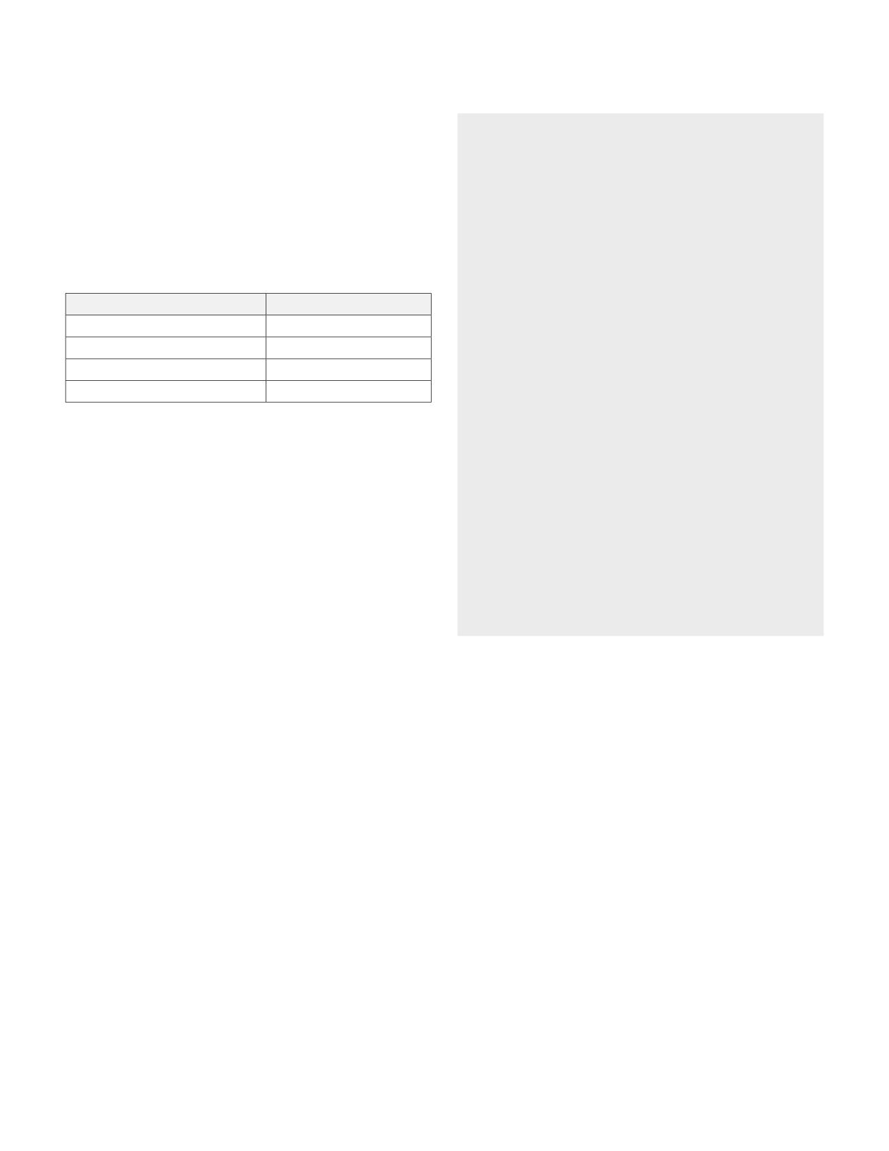
Device
Insertion Inductance
bandwidth while providing practical selection
6” twisted pair wire
123 nH
criteria for various applications.
Clamp Probe wire loop
>80 nH
• Gives an overview of different shunt resistor
Tektronix Wideband Shunts
7 to 8 nH
technologies and gives examples of several
Surface Mount Shunt
<1 nH
wideband resistors that may be used with current
Table 1. Insertion inductance of clamp-based current measurements versus
shunt probes, including Tektronix wideband shunts.
shunt-based current measurements
• Gives examples of how to select an appropriate
resistor value for Tektronix Wideband Shunts for
The need to accurately measure the voltage across
IsoVu Isolated Current Probes.
precision, high bandwidth shunts inspired the development
of the IsoVu Isolated Current Probe. This probe provides
This application note talks about several types of
galvanically isolated, 50 Ω differential inputs to provide
shunt resistors, any of which can be used with IsoVu
high bandwidth, high signal fidelity, and exceptionally high
Isolated Current Probes. This document explains how
common mode signal rejection.
to choose and apply Tektronix Wideband Shunts. The
oscilloscope used in this application note is a 6 Series B
Selecting the right shunt is critical to achieving optimal
MSO, however the isolated current probe and wideband
results when making shunt-based current measurements.
shunts are also compatible with 4 and 5 Series B MSOs.
Understanding shunt properties and careful selection from
the wide variety of available shunts will ensure accurate,
wide-bandwidth current measurements that minimize
parasitic inductance and maximize signal-to-noise ratio.
The selection process can be iterative and involves several
interconnected considerations:
• Target current range and dynamic range requirements
• Resistance value optimization for signal amplitude and
burden voltage
• Power dissipation limits and thermal management
• Bandwidth limitations due to parasitic inductance
• Test point implementation strategies
• Form factor selection based on space, power, and
bandwidth requirements
2 | WWW.TEK.COM
How to Select Shunt Resistors for High Bandwidth Oscilloscope Current Measurements
APPLICATION NOTE
Establishing Characteristics of the Current to be Measured
The target current RMS value, peak current, and ideal
Pulsed vs. Continuous Current
bandwidth are the first places to start exploring shunt
If a signal is periodic or pulsed, shunt resistors can
options. These factors will all affect downstream variables
handle significantly higher peak currents compared to
like burden voltage, resistor value, power dissipation,
continuous current.
insertion inductance, and compensation strategy.
For very short on-times (narrow pulse widths), the average
If the maximum current is dominated by a steady state DC
power dissipated by the shunt is much smaller than the
value with small transients or excursions, the DC current
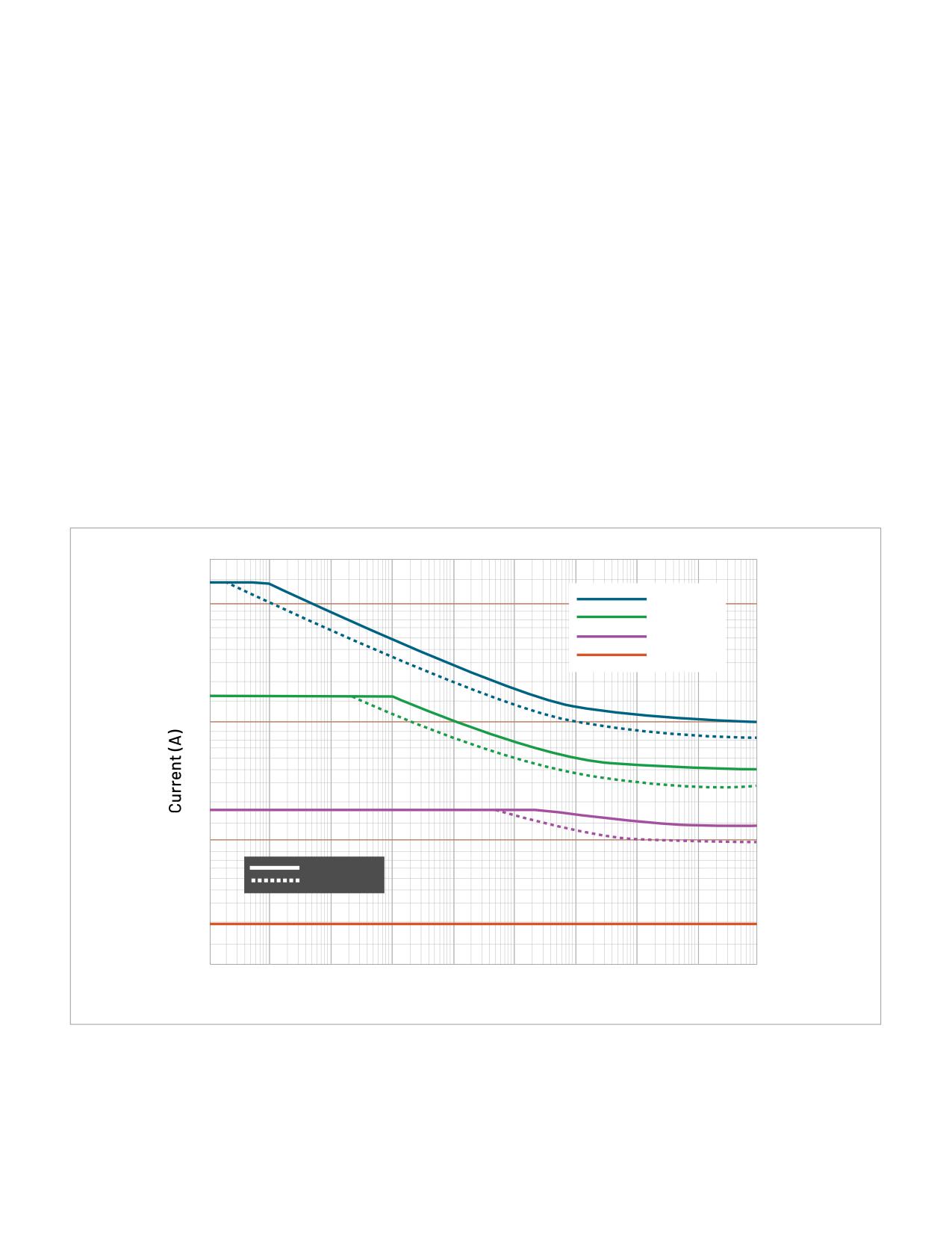
power dissipated for a continuous current. This is illustrated
can be used to establish the maximum RMS current, while
in Figure 1, which shows the relationship between maximum
allowing headroom for anticipated transients. However, in
current and pulse width for Tektronix wideband shunts.
many cases transients and excursions may be large and may
dominate range and dissipation considerations. In the case
For example, Figure 1 shows how a 5 mΩ wideband
of dissipation, pulsing the current can usually extend the
shunt can handle a 200 A square or triangle pulse of
power handling capability of a shunt.
10 µs pulse width but would be limited to 12 A RMS for a
continuous signal. Note that specific shunts may have
duty cycle limitations to allow energy to dissipate between
pulses. Maintaining a low duty cycle is good practice
whenever possible.
TICS0005
100
TICS0050
TICS0500
TICS5000
10
1
25 °C ambient
85 °C ambient
0.1
1 µ
10 µ
100 µs
1 m
10 m
100 m
1
10
100
1000
Pulse Duration (s)
1844-03
Figure 1. Maximum current by pulse duration for Tektronix Wideband Current Shunts.
WWW.TEK.COM | 3

How to Select Shunt Resistors for High Bandwidth Oscilloscope Current Measurements
APPLICATION NOTE
Bandwidth of the Current Signal
Better Dynamic Range
Traditionally, bandwidth has been of secondary concern for
Better Bandwidth
current measurements. However, with the advent of fast
switching technologies such as GaN and SiC, and dynamic
loads such as GPUs and FPGAs, rise-times have decreased
Shunt
dramatically. By approximating the measurement system
Resistance
as a first order system, one can estimate the bandwidth of
required to measure a desired rise-time.
0.35
Bandwidth =
(1)
Better (Lower) Burden Voltage
tr
Better ( Lower) Power Dissipation
Where tr is the 10% to 90% rise time of the signal.
Figure 2. Choosing a shunt resistor value requires balancing range, bandwidth,
For example, a load device that draws current with a rise
voltage drop and power dissipation.
time of 1 ns implies an estimated bandwidth of 350 MHz.
With the expectations that trade-offs are inevitable,
one can calculate an ideal resistance and then check the
Resistor Value Selection
other parameters to determine what, if any, trade-offs
To select the right shunt resistor, one must choose the
are needed.
highest value resistor that will survive the RMS current
while not violating the DUT’s load impedance or burden
Acceptable Burden Voltage
voltage limits. In high-bandwidth applications, low insertion
Higher resistance increases voltage drop across the shunt,
inductance is also an important criterion. Thus, the process
lowering the final rail voltage experienced by the load. This
involves several trade-offs.
factor can matter for any load but is especially critical for
low-voltage processors that have a 5% power rail tolerance.
Anticipating Design Trade-offs
(e.g. ±40 mV tolerance on a 0.8 V core voltage power rail).
If an ideal resistor was available with zero inductance and
unlimited power dissipation, then one could choose the
Calculate First-pass Resistance Based on
value based solely on noise and acceptable voltage drop. In
Current and Burden Voltage
reality, it is important to understand that the specifications
Assuming decoupling capacitors are in place to support
must balance several competing factors.
voltage levels, the burden voltage imposed by the shunt will
be determined by the RMS input current. This information
1.
Burden Voltage: Lower resistance decreases voltage
can be used to estimate the resistance of the shunt.
drop across the shunt, reducing the impact on the
device being powered (i.e. lowering the final rail voltage
Vburden(max)
Rshunt =
(2)
experienced by the DUT).
IRMS
2. Power Dissipation: Lower resistance decreases power
For example: a 40 mV voltage budget with 8 ARMS current
dissipation in the shunt.
allows a 5 mΩ resistor.
3. Signal Amplitude: Higher resistance provides larger
Of course, calculations may produce non-standard values. If
signal amplitude, raising signal-to-noise ratio
the burden voltage is a rigid constraint, it will be necessary
4. Measurement Bandwidth: Both higher resistance
to drop down to the next lower standard resistance value.
and lower insertion inductance increase the corner
Resistor tolerance will translate into current uncertainty, so
frequency of the shunt.
this should also be considered.
Calculate Power Dissipation
The next limiting factor is power dissipation in the shunt.
Pavg = I2 · R
(3)
4 | WWW.TEK.COM
How to Select Shunt Resistors for High Bandwidth Oscilloscope Current Measurements
APPLICATION NOTE
With a known RMS target current and resistance, one can
range on a TICP probe has an NSD of 4.7 nV/√Hz. Assuming
calculate average power dissipated. Although the maximum
a bandwidth of 200 MHz and using a 5 mΩ shunt results in a
power dissipation for specific shunts will vary by device and
13.3 mARMS noise floor according to Equation 6.
thermal conditions, good rules of thumb are to shoot below
Since lowering the shunt resistance increases the noise
3 W for larger CVRs and 1 W for SMD devices.
floor for current measurements, if this same measurement
Example: By applying Equation 3, a 5 mΩ resistor
were performed on a 3.3 mΩ shunt, the noise floor would
experiencing 8 ARMS current needs to dissipate 1/3 W of heat
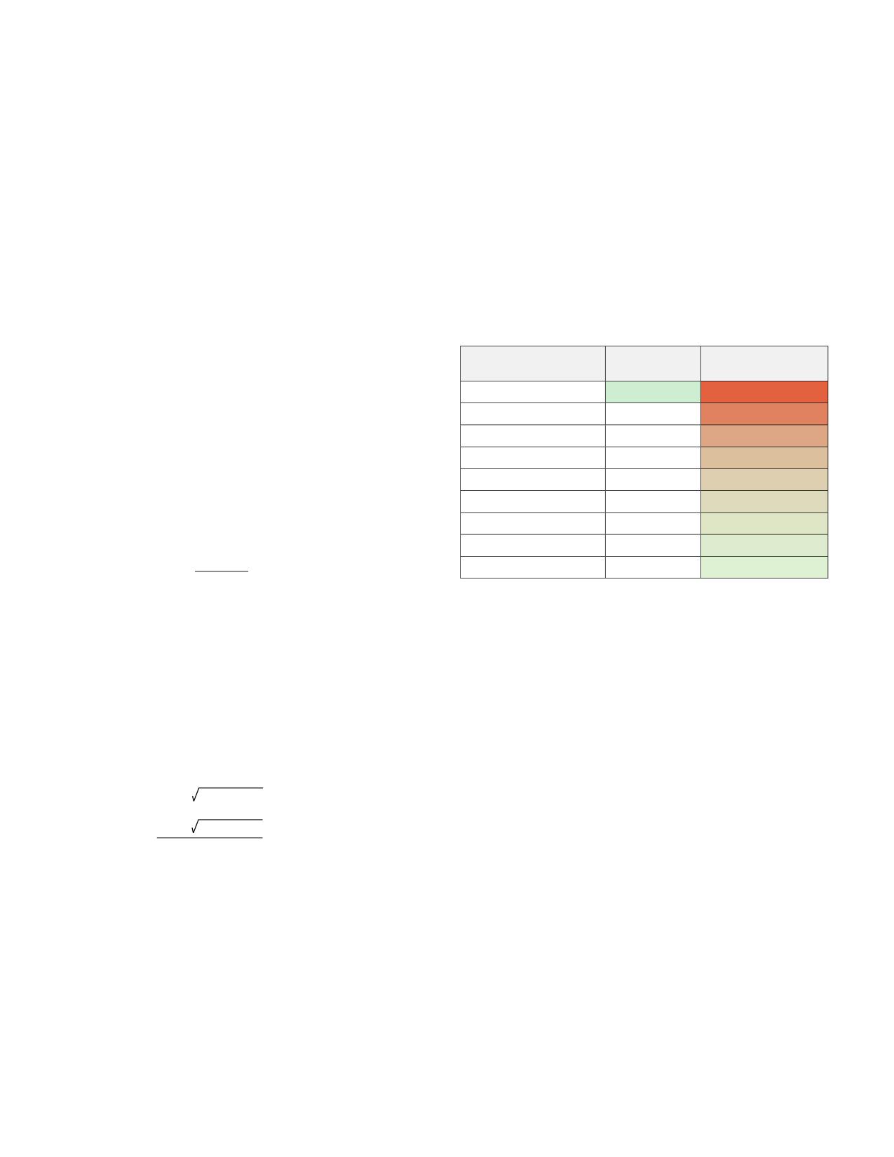
increase to 20 mARMS. Table 2 shows how different shunt
continuously. That power value is easily achievable with
values (Column A) can make the same 12 A measurement,
SMD devices and trivial for bus bars, wideband shunts, and
where noise floor (Column B) drops with higher resistance,
other dedicated current viewing resistors.
but at the cost of more power dissipation in the shunt
(Column C).
After determining the likelihood that a shunt will survive
the current measurement, the next task is to optimize the
Shunt Value to Measure
Noise Floor at
Power Dissipation at
Imax Amps (Ω)
BW (A RMS)
100% Duty Cycle (W)
measurement for dynamic range, bandwidth, and insertion
inductance.
54.2E-3
4.5E-3
7.8
41.7E-3
5.1E-3
6.0
Verify Signal Amplitude and Check Noise Floor
29.2E-3
4.6E-3
4.2
The measurement system being used to measure the
20.8E-3
5.9E-3
3.0
voltage drop across the shunt will determine the lowest
15.0E-3
5.9E-3
2.2
measurable current. This may be specified as a resolution,
10.8E-3
7.2E-3
1.6
or as the noise floor of the system. Ohm’s law relates voltage
7.5E-3
8.9E-3
1.1
noise floor to current noise floor.
5.0E-3
13.3E-3
0.7
Vnoisefloor
3.3E-3
19.9E-3
0.5
Inoisefloor = Imin =
(4)
(
Rshunt
)
Table 2. Spreadsheet calculations using Equations 3 and 5. NSD values
Where I and V are in amps (RMS) and voltage (RMS)
are for Tektronix Isolated Current Probe. Maximum current is 12 A and
target bandwidth is 200 MHz. Note the interaction between shunt value,
respectively.
measurement system noise floor and power dissipation for the specified
maximum current and bandwidth.
From this inverse relationship it is clear that a larger shunt
resistance decreases the minimum measurable current.
To ease some of these calculations with the Tektronix
Isolated Current Probe, several calculators are posted on
The voltage noise of the system increases with the
the Tektronix website. If the shunt value is known, use TICP
bandwidth of the measurement. Noise Spectral Density
Current Calculator to see the noise floor and dynamic range
(NSD), is measured in V/√Hz and relates the total bandwidth
for different TICP settings. If the target current is known
of the system to noise, as shown in Equation 6.
and the shunt is still undecided, use TICP Shunt Calculator
(5)
to see how different shunt values impact the noise floor
Vnoisefloor = NSD · Bandwidth
and dynamic range; just don’t forget to factor in power
NSD · Bandwidth
dissipation and burden voltage!
Inoisefloor =
(6)
Rshunt
Example: The 8 ARMS current from the previous example has
Shunt Inductance and Bandwidth
occasional impulses up to 12 A which need to be measured.
As explained in the previous section, resistor value selection
In other words, the system must be able to handle 8 ARMS
affects dynamic range, but it also interacts with a shunt’s
continuous, but be able to measure up to 12 A. On a 5 mΩ
parasitic inductance to limit the effective bandwidth of the
shunt, 12 A implies a 60 mV measurement. Probe and scope
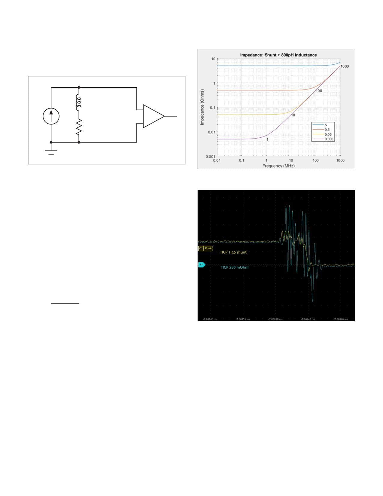
measurement system. At a first order level, a shunt resistor
ranges and offsets may also come into play. For example,
can be modeled as a single pole RL circuit: a resistor and
a TICP isolated current probe in its ±45 mV range enables a
inductor in series. This basic model ignores transimpedance
60 mV measurement with 15 mV of offset. The ±45 mV input
WWW.TEK.COM | 5
How to Select Shunt Resistors for High Bandwidth Oscilloscope Current Measurements
APPLICATION NOTE
and coupling effects which can be significant but are very
difficult to characterize and model correctly [4]. In this
application note the simplified model will be used.
L
+
I
_
R
Figure 3. A practical shunt resistor can be modeled as a series RL circuit.
Figure 4. Simulated uncompensated frequency response of different shunt
resistor values. Higher shunt resistance increases bandwidth.
In systems with highly dynamic currents, that is, high di/
dt, even small inductances can generate disruptive voltage
transients. Even if the circuit is designed to tolerate
transients from added inductance, voltage spikes and
ringing can show up in oscilloscope measurements due to
probing parasitics. Because of this potential impact to both
system performance and measurement quality, designers
and test engineers avoid adding inductance.
For our simplified model, Equation 7 gives the relationship
between shunt resistance, series inductance, and the
corner frequency at which the impedance of the shunt
results in a 3 dB increase in voltage drop across the
physical shunt.
Rshunt
(7)
ƒc =
2 · π · Lshunt
This relationship makes it clear that maximizing the
resistance of the shunt has a positive effect on bandwidth.
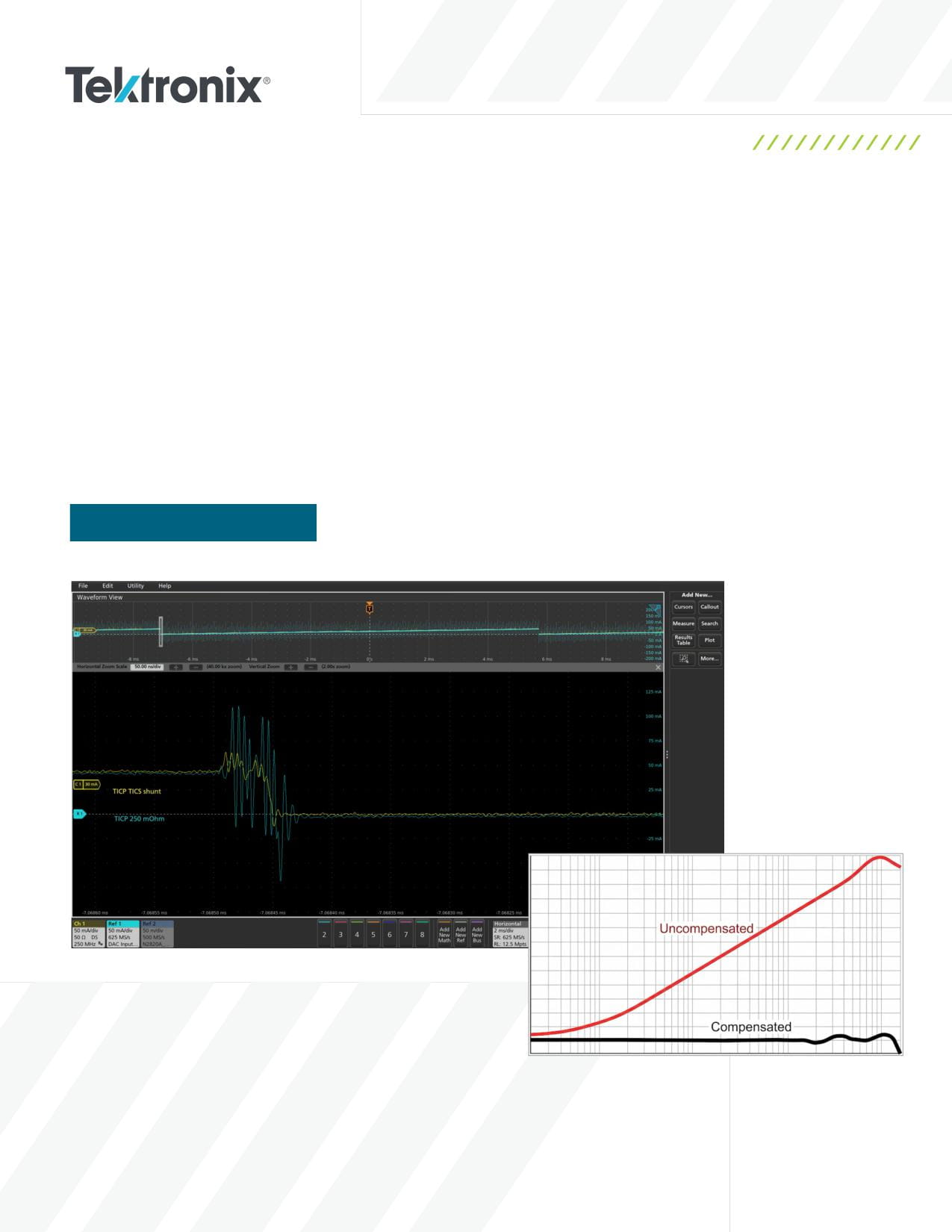
Figure 5. The yellow trace is from a compensated wideband shunt. The cyan
trace is from an uncompensated resistor. Both traces are captured using the
Figure 4 demonstrates this by showing curves for
same probe to measure voltage drop.
increasing resistance values. Above the corner frequency
(fc) the inductive reactance increases the impedance of the
Individual SMD resistors can have several nanohenries
shunt, so its response is no longer flat.
of inductance. Designers sometimes place four to eight
higher value resistors in parallel rather than using a single
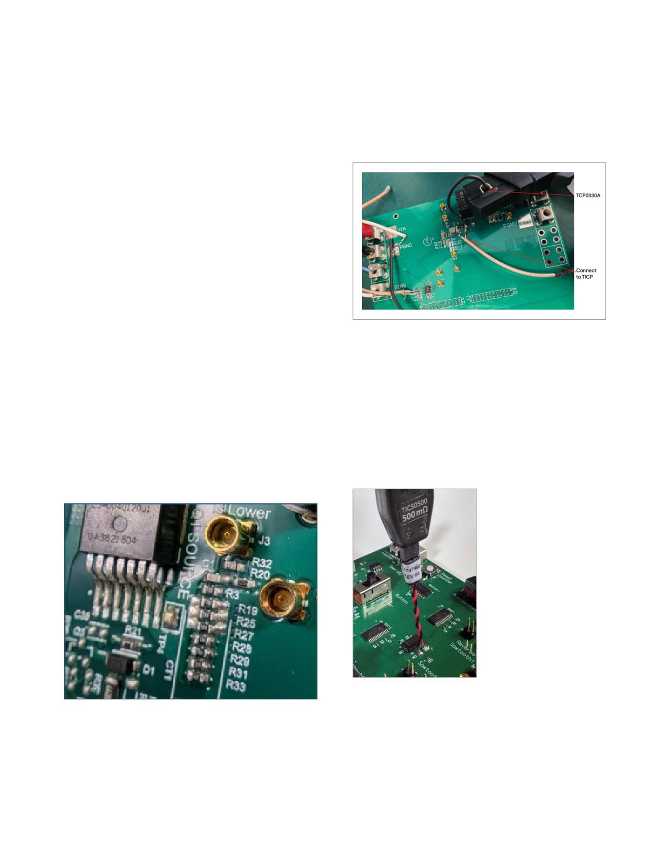
component to implement a shunt. Figure 6 shows an
example of this approach. This reduces both the resistance
and inductance of the shunt. However, this approach has
practical limits as current stops being distributed evenly at
wider form factors.
6 | WWW.TEK.COM
How to Select Shunt Resistors for High Bandwidth Oscilloscope Current Measurements
APPLICATION NOTE
Capacitors may also be used to compensate for the
On this board, the IS_LOWER test point at MMCX connector
series inductance and flatten frequency response for
J3 is designed into the board, complete with
an order of magnitude or more. Additional detail on this
compensating pole at C1, R32, and R20.
technique may be found in the Tektronix white paper
2. Existing Shunt Modification: Quick implementation,
Compensating for Series Inductance in Shunt Resistors for
may degrade signal integrity.
High Frequency Measurements. Newer shunts, optimized
for lower insertion inductance and higher bandwidth, may
include compensation networks to tune the measurement
frequency response. Tektronix Wideband Shunts integrate
a compensation network and this is described in a
subsequent section.
One important note is that although the measurement
quality may be improved through probe compensation,
the DUT still experiences the insertion inductance of the
shunt. It is only in the measurement that the effects of the
inductance are compensated.
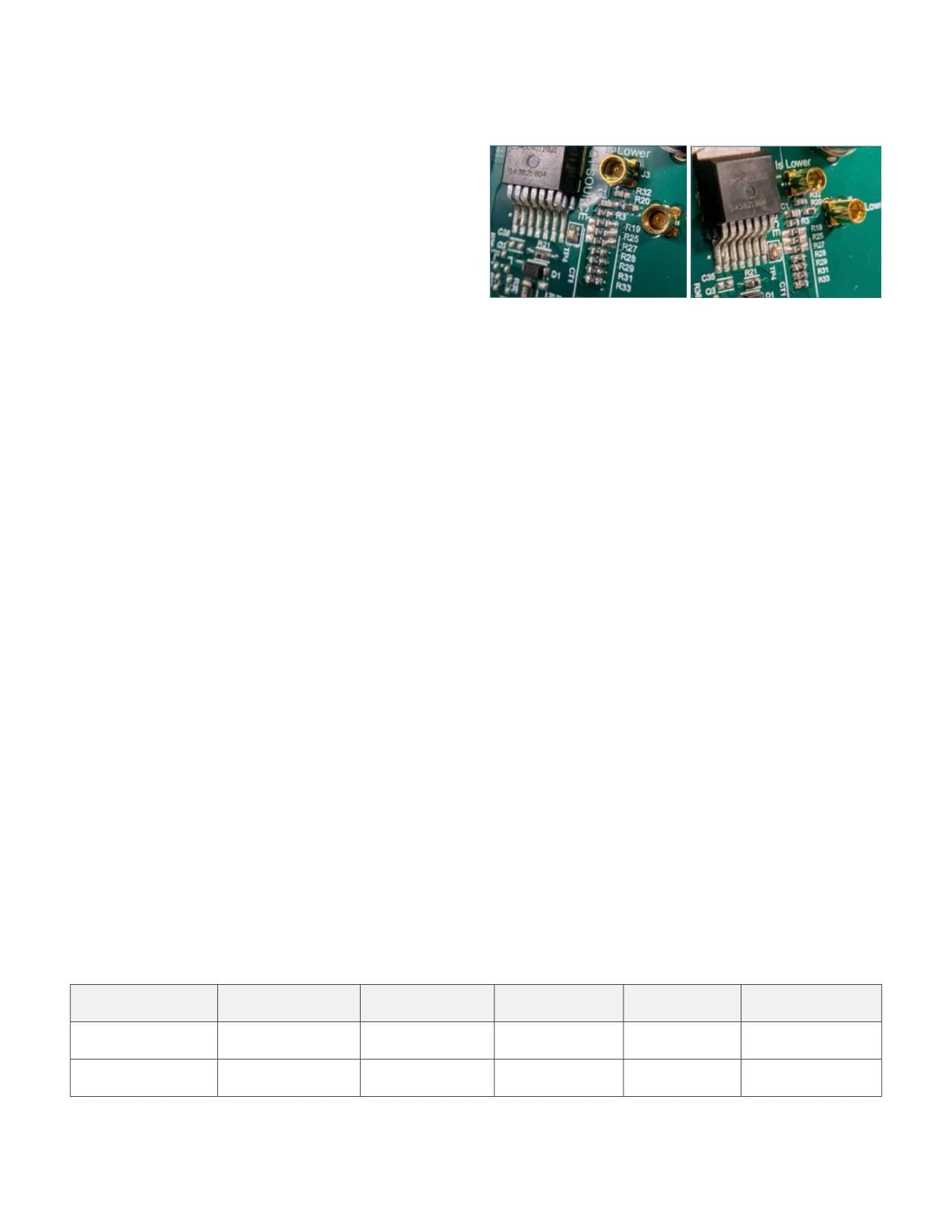
Figure 7. A 50 Ω coaxial cable, terminating in an MMCX connector, soldered
across a surface mount shunt. In this example, the clamp-on current
Examples of Test Point
probe is used to compare results.
Implementation
In this case, the DUT includes a built-in shunt. Figure 7
Ideally the shunt resistor, compensation network, and test
shows how an existing 0.1 Ω SMD shunt has an MMCX
points are all built into the board design. In the second best
cable soldered across it, allowing a TICP current
case, a shunt resistor already exists on the board. And
measurement. This implementation does not include a
finally, there are cases where no measurement point exists
compensation circuit for the parasitic inductance which
and the entire chain needs to be added.
amplifies high frequency ringing.
Implementation Strategies
3. Complete Addition: Maximum flexibility, highest
1.
Integrated PCB Design: Best performance, requires
complexity.
early planning.
Figure 8. Using a probe-based wideband shunt connected via twisted pair.
Figure 6. An integrated current test point using a high bandwidth MMCX
If no provisions have been made for a shunt, the DUT must
connector with compensation.
be carefully modified. This can involve cutting power traces
or lifting legs of components to place a resistor in-line.
Figure 8 shows an example in which, after cutting a current
WWW.TEK.COM | 7
How to Select Shunt Resistors for High Bandwidth Oscilloscope Current Measurements
APPLICATION NOTE
carrying trace, a twisted pair wire was added in series
SMD Resistors
with the current flowing through a newly added shunt. This
design is convenient but adds the most insertion inductance
into the current measurement path, impacting the device
behavior. Replacing the Y-lead with square pins or putting
the SMD directly across the cut trace can reduce insertion
inductance.
Connector Choices
Figure 9. Built-in SMD shunt resistors. In this application 8 devices are wired
In addition to the shunt location and compensation,
in parallel to reduce the shunt resistance and parasitic inductance, as well as
distribute current and control dissipation.
the physical connection to the device will also impact
measurements based on their sensitivity to radiated
SMD Resistors come in a wide variety of form factors
emissions. In the examples above, MMCX, square pins, a
and ohmic values, making them a flexible and affordable
coaxial cable with MMCX connector, and twisted pair with
option for many applications. The tradeoffs of SMD
square pins were shown. These different methods have
devices are their limited power dissipation capabilities and
different levels of sensitivity to radiated emissions and care
uncompensated frequency response.
should be taken to choose the best connection.
Inductance for SMD resistors can be low to medium, often
Shielded test points using MMCX, SMA, and coaxial cables
landing in the few nanohenries range. The form factor
will perform the best, as the outer braid provides effective
has flexible options with the caveat that as the width of
shielding to the center conductor. Even better than coaxial
the device increases relative to the length, the resistor
is a twinax cable such as those used with the Tektronix
starts to look more like a distributed transmission line
Wideband Shunts. Twinax cables put both conductors
and less like a lumped element. Impedances vary based
inside a third, braided shield-protecting both positive and
on the probing position and therefore currents start being
negative conductors from EMI with the added benefit of true
distributed unevenly across the SMD resistor. This effect is
differential signaling.
called transimpedance[4] and will impact both the effective
inductance and any measurements attempted on the SMD
Shunt Resistor Technologies and
device. It’s also likely that this transimpedance is non-
Form Factors
linear, meaning the effect changes with different current
amplitudes or different step speeds.
For high-bandwidth measurements, the IsoVu Isolated
Current Probe can be used with any resistor form factor.
Nevertheless, there are tradeoffs in the different designs.
Bus Bar Shunts
Bus bars are larger than SMD devices and therefore
In-circuit shunts are often incorporated into a standard bill
can dissipate much more heat. Although they take up
of materials and used for current monitoring during regular
significant space, they are good solutions for high-current
circuit operation. They can also function as oscilloscope
measurements. For example, for a high-RMS current
shunts for validation and debug. The inductance and
measurement such as a 100 A continuous DC current with
bandwidth of these devices may or may not be specified.
a smaller 1 A transient of interest riding on top, the resistor
Table 3 gives some ballpark figures for generic components.
In-circuit Components (typical measured values)
Inductance
Shunt Type
Resistance Range
Power Rating
(typical, measured)
Package Type
Key Applications
Solder-on surface
Compact designs,
SMD Thick/Thin Film
50 μΩ-10 Ω
0.25 W-2 W
<1 nH
mount
pulsed current
High RMS current,
Bus Bar/Metal Strip
50 μΩ-10 mΩ
10-100 W
10 nH-50 nH
Solder-on/bolt-on
thermal stability
Table 3. Rough figures for generic shunt components.
8 | WWW.TEK.COM
How to Select Shunt Resistors for High Bandwidth Oscilloscope Current Measurements
APPLICATION NOTE
must dissipate the power created by the full RMS current,
Tektronix Wideband Shunts
not just the smaller signal of interest. A busbar shunt may
One family of shunts designed to work with the Tektronix
be a good choice. These devices are typically made of
Isolated Current Probe and MSO oscilloscopes is Tektronix
materials that have stable resistance over temperature and
Wideband Shunts. These plug-and-play smart shunts
can have inductance values in the 10s of nH range, but can
integrate with Tektronix oscilloscopes - auto-configuring
be subject to the same transimpedance issues as larger
the units and vertical scale, and ensuring measurements
SMD resistors.
are performed at minimal noise levels. This design
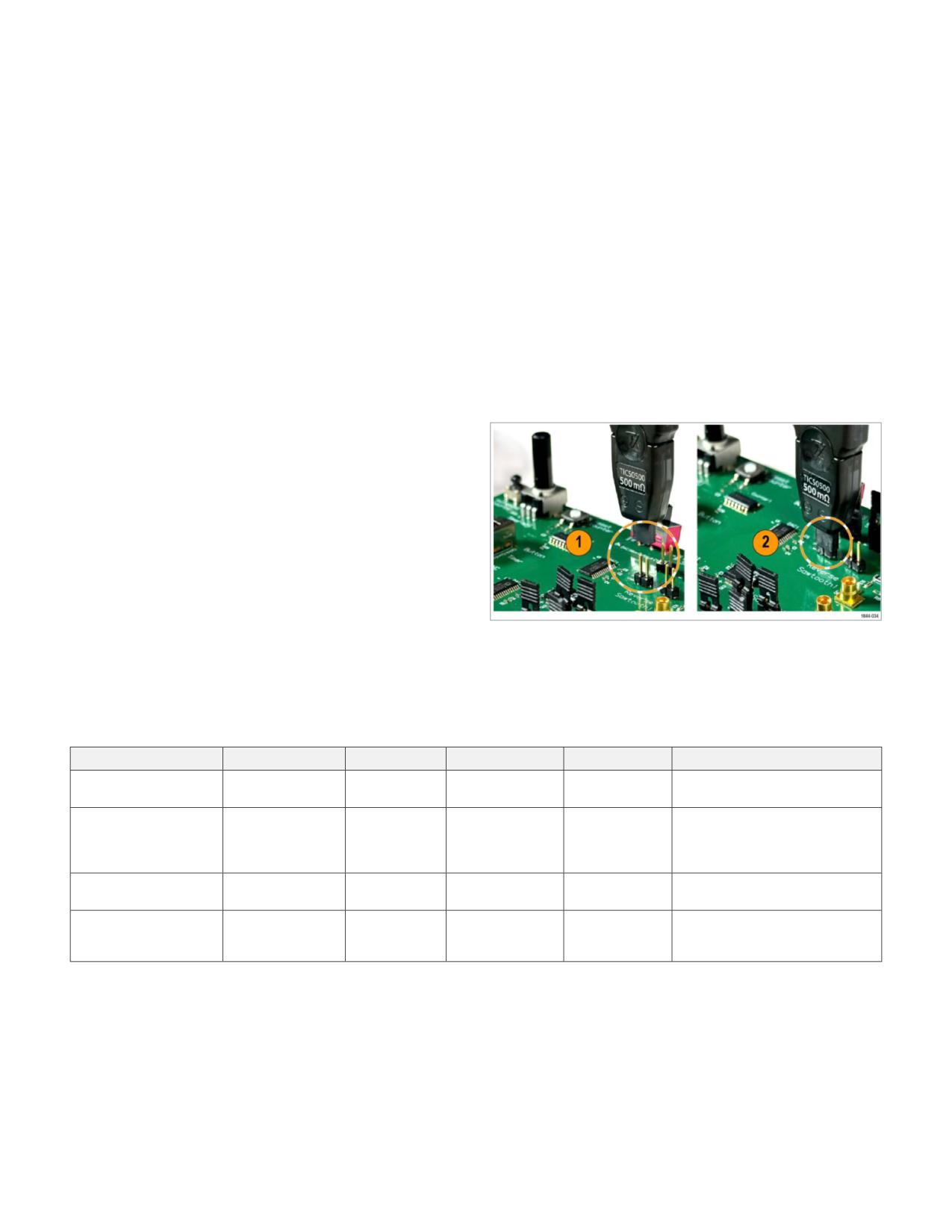
Their larger size means the designer often needs to think
interfaces with square pins (Figure 10) and connects to
ahead and design these resistors into the schematic. If
the IsoVu current probe using a flexible, low-noise twinax
your traction inverter or motor drive application already
tip. It features frequency compensation, temperature
uses current sense devices for over-current protection
compensation, and high-performance fuses to protect the
or short-circuit detection, bus bar shunts may already
test equipment (Figure 11). Values range from 5 mΩ to 5 Ω,
be incorporated in the design and it may be possible to
providing 250 MHz of bandwidth and reliable connection
measure across the existing shunt.
to boards.
Keep in mind that the vendors of these resistors do not
always think of them as high bandwidth devices. Mostly,
they are used for DC and very low frequency current
monitoring by onboard integrated circuits. This may mean
information about the resistors’ inductance, frequency
response, or bandwidth information is not available.
Special-purpose Wideband Shunt Devices
Specialty shunts, optimized for testing, are also available.
These shunts are often connected temporarily or connected
Figure 10. Tektronix wideband shunts can connect directly to 0.025 in. square
pins on 0.1 in. centers, shown in Reference 1. The probe tip and shunt are shown
as part of an evaluation or test system. Tektronix Wideband
attached to the pins in Reference 2.
Shunts fall into this category. In addition to the Tektronix
shunts, other types of shunts known to work well with the
IsoVu current probe are listed in Table 4.
Shunt Type
Resistance Range
Power Rating
Inductance
Package Type
Key Applications
Tektronix Wideband
Square pin, re-
High bandwidth, precision
5 mΩ to 5 Ω
1 W
7 to 8 nH
Shunts [1]
usable
compensation
~2 pH reported
PCB-integrated
PDN, VRM, load-step, and WBG
Not broadly
in-system; tens
thin-film /
Picotest
1 mΩ to 50 mΩ
switching measurements with
published
of pH plausible by
surface-mount
minimal circuit disturbance
implementation
style
PMK Ultra Fast Current
Solder-in with
WBG testing on devices sensitive to
1 mΩ to 52 mΩ
3 W
< 150 pH
Shunts [2]
low L pads
insertion inductance
Through-hole
T&M Research Current
WBG testing on devices sensitive to
1 mΩ to 50 mΩ
3 W and up
Not published
solder mount,
Viewing Resistors [3]
insertion inductance
panel mount
Table 4. Wideband shunts designed for testing applications
WWW.TEK.COM | 9
How to Select Shunt Resistors for High Bandwidth Oscilloscope Current Measurements
APPLICATION NOTE
Combined with a Tektronix oscilloscope, software, and isolated current probes, these wideband shunts enable precise
characterization of standby and operating currents in embedded designs, high-performance computing systems, or other
applications that require precision high-bandwidth current measurements with continuous shunt dissipation of 1 W or lower.
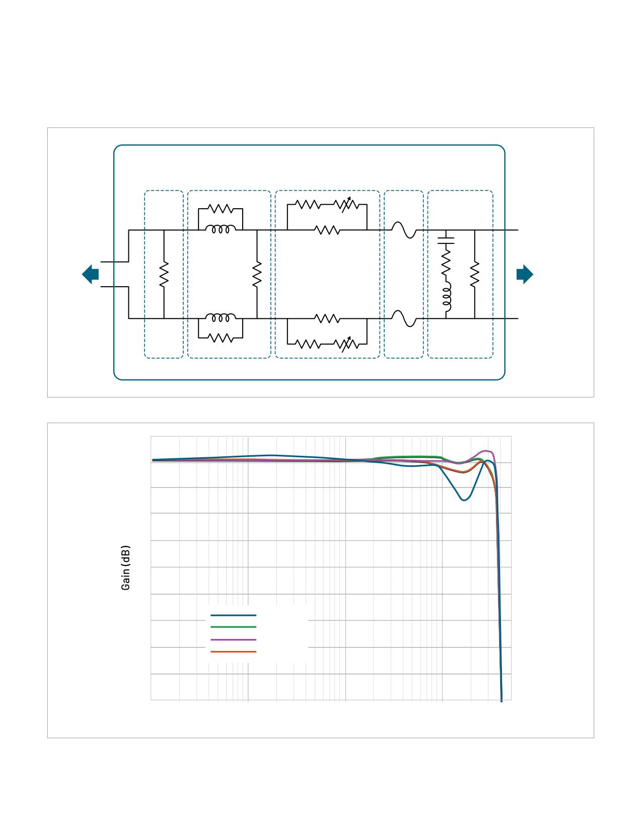
Tektronix Wideband Shunt
Precision
Frequency Response
Resistor
Compensated Pole
Temperature Compensation
Fuses
Flatness Correction
To Twinax
To DUT
Cable (probe)
Figure 11. Tektronix wideband shunts include bandwidth compensation, temperature compensation, overvoltage and overcurrent protection.
2
0
-2
-4
-6
-8
-10
TICS0005
-12
TICS0050
TICS0500
-14
TICS5000
-16
-18
0.1
1
10
100
500
Frequency (MHz)
1844-030
Figure 12. A precision compensation network in the Tektronix wideband shunts flattens the frequency response out to 250 MHz.
10 | WWW.TEK.COM
How to Select Shunt Resistors for High Bandwidth Oscilloscope Current Measurements
APPLICATION NOTE
Current Viewing Resistors from T&M Research
from its large form factor. The low insertion inductance
requires a wide space on the test board and the shunt is
T&M Research Current Viewing Resistors (CVRs) are a
also tall, presenting positioning challenges in crowded
popular option for current sensing and their orange labels
enclosures.
are a familiar sight in many power electronics labs. With
a coaxial body and a BNC connector, these CVRs have
advantages in shielding over an SMD or bus bar shunt. They
also offer large, high power dissipation form factors, useful
for continuous power testing. However, similar to other
shunts, parasitic inductance can impact measurement
quality and steps should be taken to control it and
understand the frequency response of the shunt.
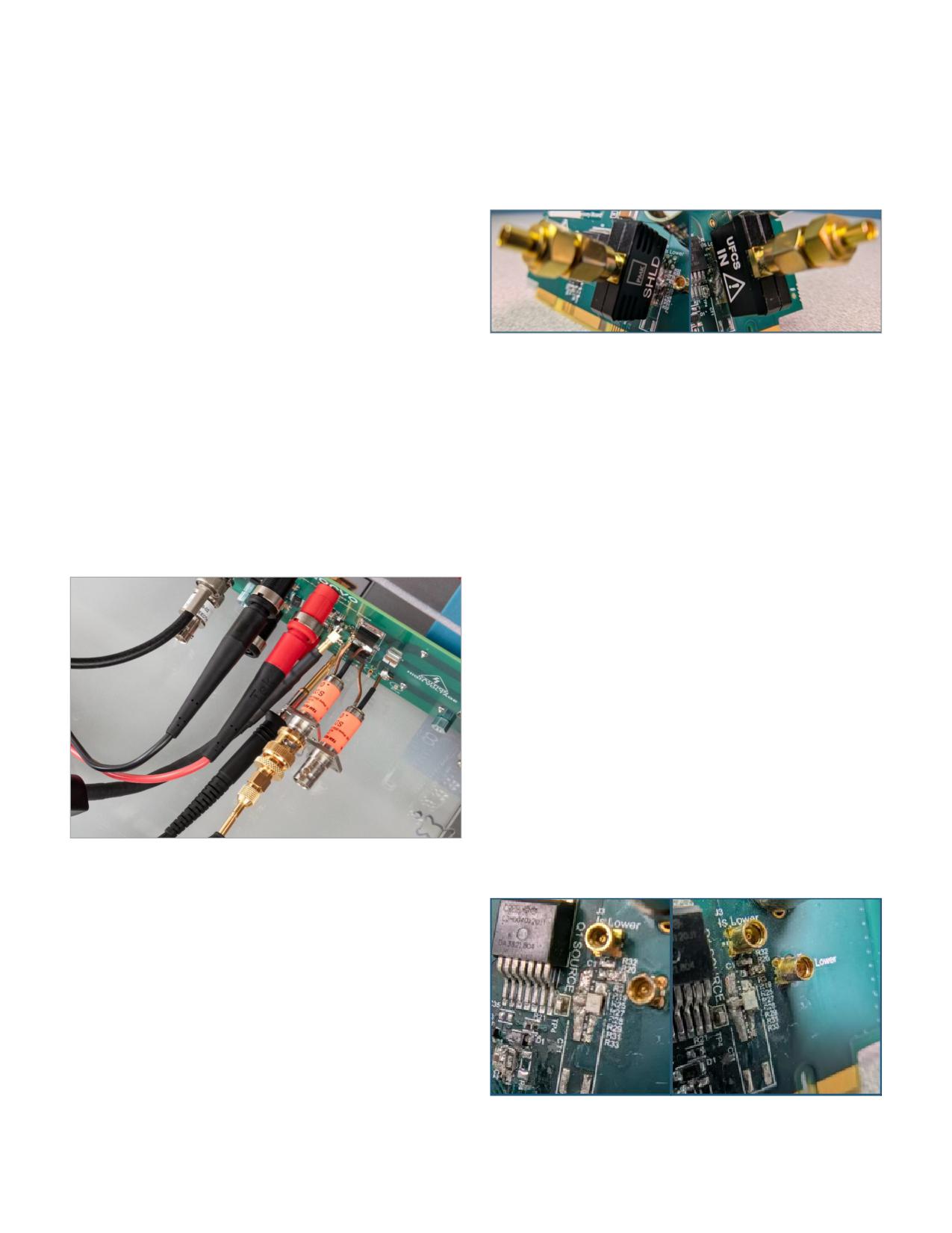
Figure 14. A PMK Ultrafast Current Shunt assembled on a circuit board.
While BNC connectors are convenient, one should use
This device is well-suited for current measurements on
caution when connecting the CVR directly to an oscilloscope
wide bandgap devices where the insertion inductance
with a cable. This grounds the low measurement terminal
is paramount, and compromises can be made to fit the
and creates a ground loop, leading to ground current
shunt onto the test board. Its cost is more in line with
injection and ground bounce. Ground bounce directly
a measurement device than a mass-produced SMD
impacts the measurement, adding ringing that is from the
component, so it’s also more suited for R&D lab benches
test setup, not the device. Combining these devices with an
than production tests.
IsoVu isolated current probe kills the ground loop through
its RF isolation barrier, providing a galvanically isolated
Picotest Ultra-Low Inductance and Ultra-High-
measurement that better reflects the DUT's performance.
Bandwidth Current Shunts
Picotest has announced a new family of resistors called
“ultra-low insertion inductance, ultra-high-bandwidth
current shunts”. They are targeted at high-speed
PDN, VRM, load-step, and wide-bandgap switching
measurements. Because of their unique footprint, the
shunts are ideally integrated into the PCB layout and used
for both R&D, validation, and in-system monitoring after
production. Picotest describes the design as a distributed
electromagnetic structure rather than a conventional
lumped resistor, where the physical construction of the
device is a critical component of its performance. They say
the unique footprint and novel construction method enables
insertion inductance in the ones or tens of picohenries,
Figure 13. IsoVu Isolated Current Probe measuring the source current on a SiC
resulting in bandwidths of several hundred MHz to 1 GHz,
FET with a T&M Research current viewing resistor.
without compensation. At the time of writing, detailed
Ultrafast Current Shunt from PMK Mess- und
Kommunikationstechnik GmbH
New current shunts from test and measurement companies
are launching every year. One is the Ultrafast Current Shunt
(UFCS) from PMK. In testing, the UFCS shows several-
hundred MHz bandwidth with a desirable rolloff, indicating
it is a frequency-compensated design. It performs well
with low insertion inductance and 3 W power dissipation
capability. The challenges with using the PMK device come
Figure 15. Prototypes of Picotest low-inductance shunts.
WWW.TEK.COM | 11
How to Select Shunt Resistors for High Bandwidth Oscilloscope Current Measurements
APPLICATION NOTE
catalog information such as specific resistance values, power ratings, and production part options has not yet been broadly
published, so these devices are best viewed as an emerging alternative in applications where minimizing measurement
disturbance is especially important.
Example application
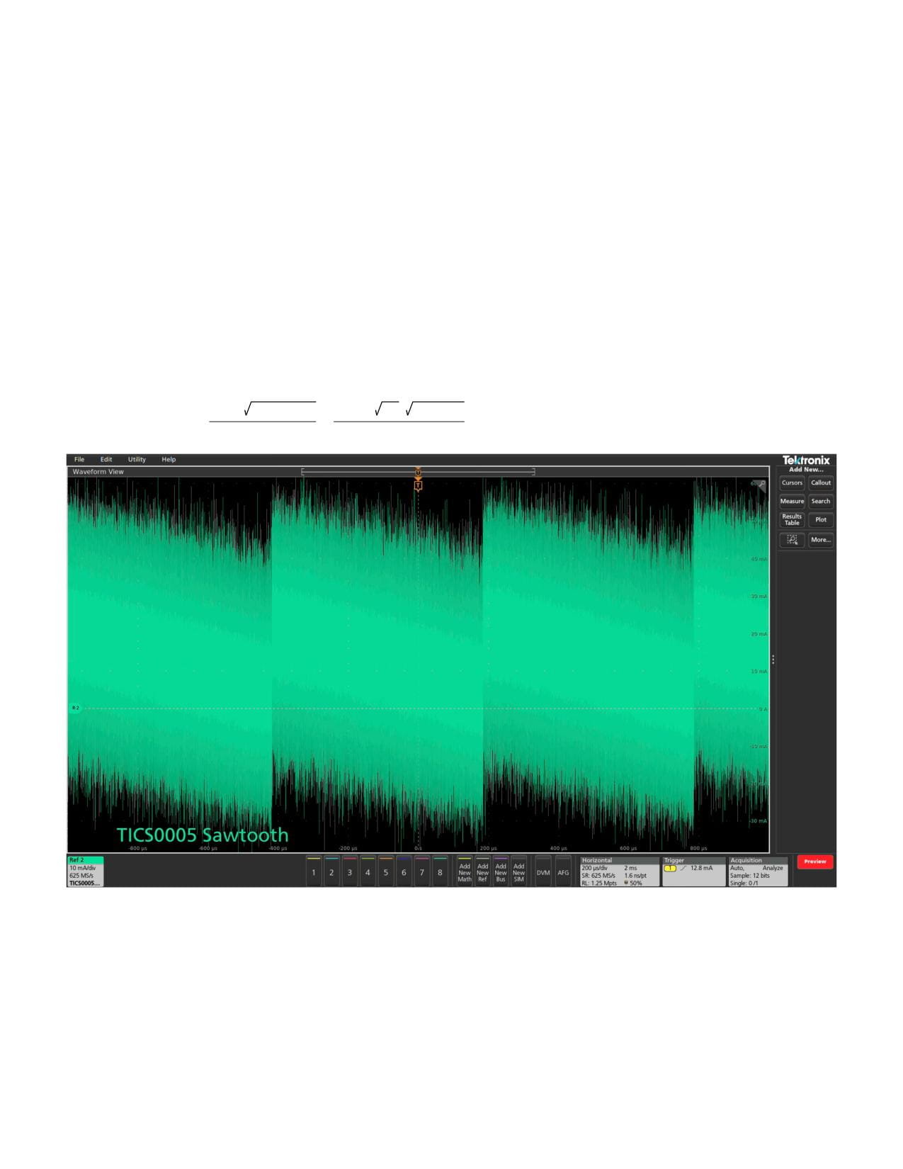
Measuring a current waveform from 0 to 20 mA with better than 78 µA resolution
Current is sourced from an IC generating a sawtooth output current waveform. The current steps to 20 mA and ramps back to
0 mA through 256 discrete levels: 78.1 µA per step. To monitor the transitions of this waveform, a measurement system with
a noise floor below 78 µA and dynamic range of 20 mA is needed (greater than 48 dB dynamic range). Burden voltage is not a
concern on this current-source IC.
A 5 mΩ shunt at 250 MHz has a noise floor of 15 mA, which is low enough to see that a 20 mA ramp exists but details about the
curve are obscured. TICP operates in its most sensitive, ±20 mV range with 4.7 nV/√Hz NSD.
NSD · Bandwidth
4.7 nV/ Hz ·
250 MHz
INoiseFloor 5 mΩ TICS =
=
= 15 mA RMS
Rshunt
5 mΩ
Figure 16. When using a 5 mΩ shunt, a 20 mA sawtooth waveform is visible through the 15 mA noise floor, but details are obscured. For this 5 mΩ shunt, the burden
voltage at 20 mA would be 100 μV.
12 | WWW.TEK.COM
How to Select Shunt Resistors for High Bandwidth Oscilloscope Current Measurements
APPLICATION NOTE
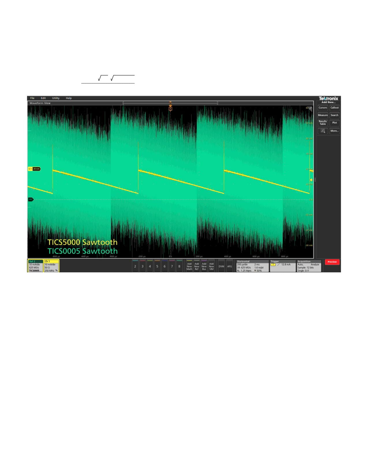
Stepping up to the 5 Ω TICS5000 with the same bandwidth lowers the noise significantly, even with the increase in NSD due
to the wider ±125 mV range. The higher input range has higher noise than the more sensitive ranges but the greatly increased
signal amplitude more than compensates for the slightly increased probe noise contribution.
8.7 nV/ Hz ·
250 MHz
INoiseFloor 5 Ω TICS =
= 28 µA RMS
5 Ω
Figure 17. Noise is significantly reduced with the 5 Ω Wideband Shunt on Channel 1, revealing resonances and other details about the DUT’s performance. For this 5 Ω
shunt, the burden voltage at 20 mA would be 100 mV.
Key takeaways:
Conclusion
Selecting the appropriate shunt resistor for high bandwidth
• Current range and dynamic range requirements drive
current measurements requires careful consideration of
initial selection criteria
multiple factors including current range, power dissipation,
• Power dissipation limits constrain resistance
resistance value, form factor, bandwidth limitations, and
value selection
test point implementation. The selection process involves
• Form factor selection affects bandwidth, power
balancing competing requirements to achieve optimal
handling, and cost
performance for the specific application.
• Parasitic inductance limits bandwidth, affects the DUT,
and may require compensation
• Test point implementation strategy affects
measurement accuracy and repeatability
WWW.TEK.COM | 13

How to Select Shunt Resistors for High Bandwidth Oscilloscope Current Measurements
APPLICATION NOTE
DC gain accuracy: The specified maximum deviation of
References
measured DC amplitude from the ideal value, accounting
1.
IsoVu Isolated Current Probes product page; https://
for gain (slope) error, verified using precision DC reference
measurements.
probes/isovu-isolated-current-probes
DC offset or offset current: A DC current added to an AC
2. PMK Ultra-Fast Current Shunt UFCS product page;
signal. It shifts the waveform up or down relative to a 0 A
reference.
3. T&M Research Current Viewing Resistor product
Insertion Inductance: The effective inductance added to
php?page=products
a circuit when a shunt is placed in series with the current
4. Sandler, Steven “Making Sense of Two-Wire Current-
path, measured in Henries. It represents the total inductive
Sense Resistors”; https://www.picotest.com/insights/
contribution of the resistor element and its physical current
july-2012-how2power-making-sense-of-two-wire-
loop. It limits the risetime accuracy and high frequency
current-sense-resistors/; originally published in
performance of current measurements.
How2Power Today, July 2012
Kelvin connection: A 4-wire connection approach for
measuring resistance or impedance in which separate
Glossary
conductors are used to inject current and measure voltage.
These terms may be encountered during shunt selection.
This reduces the effect of lead resistance or inductance on
These are general definitions and specific qualifications
the measurement.
may be applied, depending upon the manufacturer.
Maximum current: Maximum continuous current in Amps
Bandwidth (or bandpass): A range of signal frequencies.
RMS for shunt to maintain performance including any
Unless otherwise indicated, oscilloscope-based system
derating for temperature, if applicable. Exceeding this
bandwidth is specified from DC to an upper frequency at
current also risks permanent damage to the shunt.
which the signal amplitude changes by 3 dB. For shunt
resistors the upper frequency is defined by a +3 dB increase
Maximum pulse current: Maximum current for a shunt as a
in voltage, due to inductive reactance.
function of pulse width, usually specified as a plot of peak
current versus on-time. The maximum suitable current
Burden voltage: The voltage drop across a shunt resistor,
declines as pulse width increases.
proportional to current. Usually determined as a worst-case
value at maximum current.
Maximum voltage: This voltage reflects an absolute
maximum voltage across a resistor, above which damage to
Continuous power rating: The maximum steadystate power
the resistor is likely.
a shunt resistor can dissipate without damage, specified
as average power in watts at a specified temperature or
MMCX Connector: Micro-Miniature Coaxial connector
temperature range.
(MMCX) is a small, 50 Ω, RF precision connector with snap-
on coupling and 360-degree rotation.
Current rating, thermal derating: The reduction in a shunt
resistor’s maximum allowable continuous power dissipation
Noise Floor: The minimum measurable voltage or current
as ambient temperature rises. This may be shown in shunt
level set by the measurement system’s intrinsic noise,
datasheets as a derating curve plotting maximum power
specified for a frequency range (bandwidth) below which
versus temperature.
a measurement system cannot distinguish signal from
noise. Typically measured in VRMS or ARMS for shunt-based
Current sense resistor: A resistor optimized for in-circuit
measurements.
current measurements, practically synonymous with “shunt
resistor”.
NSD: Noise Spectral Density, or more specifically voltage
noise spectral density, captures the fact that noise
Current viewing resistor (CVR): A shunt-style resistor
increases with bandwidth and specifies the amount of RMS
optimized for dynamic measurement and simulation
voltage noise in a signal per square root Hertz.
models; often used in test and prototyping contexts.
14 | WWW.TEK.COM

How to Select Shunt Resistors for High Bandwidth Oscilloscope Current Measurements
APPLICATION NOTE
Operating Temperature Range: Range of temperatures over
Temperature Coefficient (Tcr): The effect of temperature
which a shunt is expected to meet its specified electrical
on resistance, in ohms or ppm per degree C. For resistors
performance.
this is a positive value, that is, increasing temperature
increases resistance. A low temperature coefficient is
Power coefficient: Change in resistance per watt of power
usually desirable for shunt resistors.
dissipation, typically in ppm/W.
Thermal Resistance: A measure of a resistor’s temperature
Pulse energy capacity: A specification that gives the
rise per watt of power dissipation (°C/W).
maximum pulsed energy, in joules, that can be dissipated by
a shunt resistor, where Emax = R · ∫i2(t)dt.
Tolerance: Uncertainty of a shunt’s resistance as a
percentage of nominal, at a specified temperature.
Self-heating: The temperature increase of a resistor due
to the power it dissipates internally, typically expressed
in terms of thermal resistance, or temperature rise per
watt (°C/W).
WWW.TEK.COM | 15

Contact Information:
Australia 1 800 709 465
Austria* 00800 2255 4835
Balkans, Israel, South Africa and other ISE Countries +41 52 675 3777
Belgium* 00800 2255 4835
Brazil +55 (11) 3530-8901
Canada 1 800 833 9200
Central East Europe / Baltics +41 52 675 3777
Central Europe / Greece +41 52 675 3777
Denmark +45 80 88 1401
Finland +41 52 675 3777
France* 00800 2255 4835
Germany* 00800 2255 4835
Hong Kong 400 820 5835
India 000 800 650 1835
Indonesia 007 803 601 5249
Italy 00800 2255 4835
Japan 81 (3) 6714 3086
Luxembourg +41 52 675 3777
Malaysia 1 800 22 55835
Mexico, Central/South America and Caribbean 52 (55) 88 69 35 25
Middle East, Asia, and North Africa +41 52 675 3777
The Netherlands* 00800 2255 4835
New Zealand 0800 800 238
Norway 800 16098
People’s Republic of China 400 820 5835
Philippines 1 800 1601 0077
Poland +41 52 675 3777
Portugal 80 08 12370
Republic of Korea +82 2 565 1455
Russia / CIS +7 (495) 6647564
Singapore 800 6011 473
South Africa +41 52 675 3777
Spain* 00800 2255 4835
Sweden* 00800 2255 4835
Switzerland* 00800 2255 4835
Taiwan 886 (2) 2656 6688
Thailand 1 800 011 931
United Kingdom / Ireland* 00800 2255 4835
USA 1 800 833 9200
Vietnam 12060128
* European toll-free number. If not
accessible, call: +41 52 675 3777
Rev. 02.2022
Find more valuable resources at TEK.COM
Copyright © Tektronix. All rights reserved. Tektronix products are covered by U.S. and foreign patents, issued and pending. Information in this publication supersedes that
in all previously published material. Specification and price change privileges reserved. TEKTRONIX and TEK are registered trademarks of Tektronix, Inc. All other trade names
referenced are the service marks, trademarks or registered trademarks of their respective companies.
062926 SBG 51W-74272-0