Contact us
Call
Call us at
Available 9 AM - 5 PM CET Business Days
Download
Download Manuals, Datasheets, Software and more:
Feedback
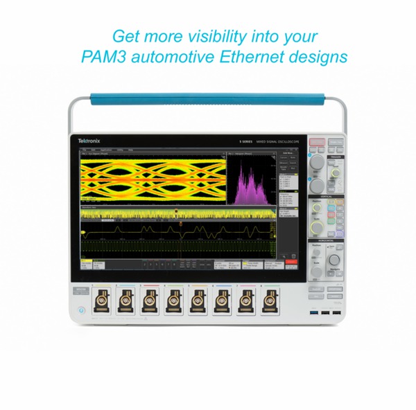
Automotive Ethernet Test Solution
1000BASE-T1/100BASE-T1 (Opt. 6-CMAUTOEN/5-CMAUTOEN) Datasheet
More Information
- Analysis Software for Oscilloscopes
- Product Support
- 5 Series B MSO
- 6 Series B MSO
- Explore more Software models
Read Online:

1000BASE-T1/100BASE-T1 (Opt. 6-CMAUTOEN/5-CMAUTOEN) Datasheet
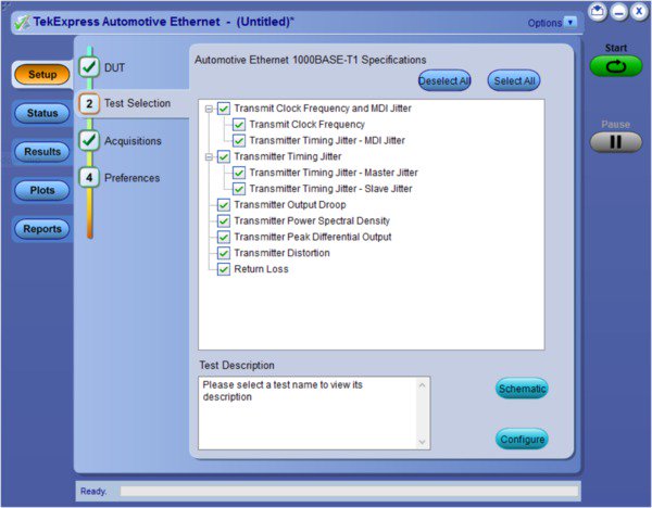
Key features
- Test Time: Fully automated with setup wizard, to perform compliance testing as per the Automotive Ethernet 1000BASE-T1 (802.3bpTM) and 100BASE-T1 (802.3bwTM) standards. The software automatically configures equipments as per test requirement which reduces overall test time.
- Test Coverage: Automotive Ethernet solution for 100BASE-T1 and 1000BASE-T1 is designed as per IEEE and Open Alliance specification. The Test coverage is as per OPEN Alliance TC8 ECU test.
- Validation and Debug: Supporting tools, such as advanced jitter analysis, help to catch problems before compliance testing, or in the event of a failure.
- Signal Qualification: In addition to compliance testing, automated tests and advanced jitter analysis tools are provided for testing your DUT under different environmental conditions.
- Comprehensive Report: Automated reporting with Pass/Fail screenshot of the waveform.
- Measurement Accuracy: The 5/6 Series MSO oscilloscope provides accurate and repeatable results with a 12-bit vertical resolution at the sampling rate of 3.125 Gs/s (5 Series MSO) and 12.5 Gs/s (6 Series MSO).
- Return Loss Measurements: The 100/1000BASE-T1 specification defines Return Loss measurement that requires a Vector Network Analyzer (VNA). A patented measurement approach in the Tektronix Automotive Ethernet Test Solution software allows the designer to perform return loss measurement using an oscilloscope, reducing the need for additional test equipment.
- ECU Clock Access: The Distortion test requires to access ECU clock which is not possible most of the time. Tektronix unique algorithm software correction method (patent pending) allows user to perform Distortion measurement without connecting clock from ECU. This method is available for 100BASE-T1 and 1000BASE-T1.
- Performance Verification: Automotive Ethernet application allows user to run Selected test for multiple times. The report shows pass/fail result of each run to study ECU performance over different run.
Automated Automotive Ethernet compliance testing
Physical layer compliance tests have been defined to ensure interoperability between different designs and hardware vendors. These requirements to perform these tests have been expanded and now cover Automotive Ethernet 1000BASE-T1 (802.3bpTM) and 100BASE-T1 (802.3bwTM). For electrical signaling, there are specific tests defined for the Physical Media Attachment (PMA), and as part of Group 1, focuses primarily on the transmitter. The 1000BASE-T1 Automotive Ethernet testing requires an oscilloscope with a minimum of 2 GHz bandwidth.
| Test Items | Test Name | Test Mode | Instrument |
|---|---|---|---|
| 97.5.3.1 | Transmitter Output Droop | 6 | 2 GHz oscilloscope |
| 97.5.3.2 | Transmitter Distortion | 4 | 2 GHz oscilloscope and AWG |
| 97.5.3.3 | Transmitter Timing Jitter (Master/Slave) | 1 | 2 GHz oscilloscope |
| 97.5.3.4 | Transmitter Power Spectral Density (PSD) | 5 | 2 GHz oscilloscope |
| 97.5.3.6 | Transmitter Clock Frequency | 1 | 2 GHz oscilloscope |
| 97.5.3.5 | Peak Differential Output | 5 | 2 GHz oscilloscope |
| 97.7.2.1 | MDI Return Loss | slave | 2 GHz oscilloscope and AWG or Tektronix VNA |
| 97.5.3.3 | MDI Jitter | 2 | 2 GHz oscilloscope |
| Test ID | Test Name | Test Mode | Instrument |
|---|---|---|---|
| 5.1.1 | Transmitter Output Droop | 1 | 1 GHz oscilloscope |
| 5.1.2 | Transmitter Distortion | 4 | 1 GHz oscilloscope and AWG/AFG |
| 5.1.3 | Transmitter Timing Jitter | 2 | 1 GHz oscilloscope |
| 5.1.4 | Transmitter Power Spectral Density (PSD) | 5 | 1 GHz oscilloscope |
| 5.1.5 | Transmitter Clock Frequency | 2 | 1 GHz oscilloscope |
| 5.1.6 | MDI Return Loss | slave | 1 GHz oscilloscope and AWG or Tektronix VNA |
| 5.1.6 | Peak Differential Output | 5 | 1 GHz oscilloscope |
The Tektronix Automotive Ethernet test solution provides automated compliance testing for 100BASE-T1 (IEEE 802.3bwTM) and 1000BASE-T1 (IEEE 802.3bpTM) requirements. The automated compliance solution includes test software that runs on a 1 GHz or greater Windows 10 OS Tektronix oscilloscope to perform all physical layer (PHY) transmitter compliance tests.
The compliance software allows for complete or selective testing of any of the transmitter electrical specifications, including complete oscilloscope control of the required setups. Software setup flexibility allows you to perform design validation, margin analysis, and repeatable compliance testing while reducing instrument setup difficulties. Additionally, the software can generate a comprehensive date-stamped test report with pass/fail results, and display waveforms and data plots.
Ordering information
Measurement names and hardware
| Measurements | Required hardware |
|---|---|
| Transmitter output droop Transmitter timing Jitter Transmitter clock frequency MDI Jitter Differential Output Transmitter power spectral density |
5/6 Series MSO with one probe |
| Transmitter distortion | AFG3152C or AWG5200 |
| Return Loss | 100BASE-T1: AFG3152C and two probes or TTR503 1000BASE-T1: AWG5200 and two probes or TTR503 |
- Required software
-
Option 5-CMAUTOEN/6-CMAUTOEN or SUP5-CMAUTOEN/SUP6-CMAUTOEN (TekExpress Automotive Ethernet compliance)
- Required hardware
-
1000BASE-T1 5 Series MSO oscilloscope (2 GHz option 5-BW-2000) or 6 Series MSO oscilloscope with minimum bandwidth of 2 GHz (Option 6-BW-2500, 6-BW-4000, 6-BW-6000, 6-BW-8000)
100BASE-T1 5 Series MSO oscilloscope (1 GHz option 5-BW-1000 or 2 GHz option 5-BW-2000) or 6 Series MSO oscilloscope with minimum bandwidth of 1 GHz (Option 6-BW-1000, 6-BW-2500, 6-BW-4000, 6-BW-6000, 6-BW-8000)
Option 5-WIN/6-WIN or SUP5-WIN/SUP6-WIN (removable SSD with Microsoft Windows 10 operating system)
- Recommended options
-
Option 5-DJA/6-DJA or SUP5-DJA/SUP6-DJA (adds Advanced Jitter and Eye Analysis measurements)
Option 5-RL-125M/6-RL-125M or SUP5-RL-125M/SUP6-RL-125M (adds 125 M record length)
Option 5-SRAUTO/6-SRAUTO or SUP5-SRAUTO/SUP6-SRAUTO (adds CAN, CAN FD, LIN, FlexRay serial bus trigger and decode)
Option 5-SRAUTOSEN/6-SRAUTOSEN or SUP5-SRAUTOSEN/SUP6-SRAUTOSEN for SENT Protocol trigger and decoder
Option 5-SREMBD/6-SREMBD or SUP5-SREMBD/SUP6-SREMBD (adds I2C, SPI serial bus trigger and decode)
- Probing
- Recommended (two required): 1000BASE-T1 TDP3500 differential probes and 100BASE-T1 TDP1500 or TDP3500 differential probes
- Signal sources (AWG)
-
Recommended: Tektronix AFG3152C signal source
Supported: Tektronix AWG5200 with high amplitude DC coupled output option or AWG70000 signal source (for 1000BASE-T1 Return Loss measurement)
- Recommended test fixtures
-
TF-XGbT Test Fixture
TF-BRR-CFD clock frequency divider (Required for Hardware clock for Distortion measurement)
- Recommended extras
-
External PC monitor
Two pairs of 50 Ω high-quality SMA or coaxial cables (four cables total) for use with AFG or AWG signal sources; all cables must be the same length
Two 50 Ω high-quality coaxial cables for use with clock divider outputs; both cables must be of the same length
One 50 Ω high-quality SMA cable for the clock divider input
One 50 Ω high-quality coaxial cable for the AFG or AWG signal source, for marker output

Tektronix is registered to ISO 9001 and ISO 14001 by SRI Quality System Registrar. Product(s) complies with IEEE Standard 488.1-1987, RS-232-C, and with Tektronix Standard Codes and Formats. Product Area Assessed: The planning, design/development and manufacture of electronic Test and Measurement instruments.
61W-61408-3


