Throughout any design process, engineers are faced with design trade-offs. Tektronix has been designing scopes with internal attenuators for many decades. However, as the bandwidth of the scope increases, more consideration has to be given to the effects of the attenuator network on signal fidelity. With today’s scopes reaching beyond 50GHz, everything in the signal path is critical. One design trade-off at this performance level is to consider internal versus external attenuation. Internal attenuation is convenient for the user, as it allows changing Volts/div settings over a larger range without having to touch the cable connection, and it allows the scope to store the calibration correction for all of the attenuator settings, so that they can be recalled and applied automatically to the measurement once a setting change has been made. However, in order to add this switchable attenuation, it is necessary to extend the signal path and add switching into this most critical part of the signal path. Here is an example of how an internal attenuation network might be constructed:
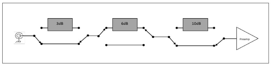
Each attenuator in the string requires two switches, and each switch adds electrical noise from the contacts. In addition, the interconnects and bypass paths have losses which have to be compensated for by DSP methods, which may also result in increased noise levels.
An alternative is to avoid placing the attenuation into the scope, so that the critical path has no switches in the input path, and has the shortest possible distance to travel from the input connector to the preamp input. Of course, this approach faces challenges if the signal being applied to the instrument is larger than the dynamic range of the preamp. In this case, it is necessary to add external attenuators. The advantage in this case is that the external attenuator can be added without the inclusion of additional switching components, so the signal integrity can be more easily maintained. Signal paths can continue to be kept to the shortest possible length. The tradeoff in using external attenuators is that you need to accurately de-embed the effects of the attenuator to maintain the high precision of the channel. Fortunately, there are now techniques and features are available to facilitate simple signal path correction for external attenuators
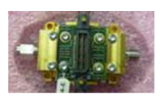
The latest Tektronix DPO77002SX scope provides an input sensitivity range of 100mVFS (10mV/div) to 300mVFS (30mV/div). This dynamic range is the result of working to optimize the signal fidelity to the maximum degree possible, which generally means that everything that is not absolutely essential is removed from the signal path, and that the path from the input connector to the preamp is kept as short as possible. To the right is a picture of the ATI module used in the 70000SX oscilloscopes. The input connector is a 1.85mm coax connector, and it is roughly 35mm from that input connector to the input of the preamp on the SiGe die that is inside the package. This very short distance is part of the key to maintaining very careful control of the signal fidelity within the instrument.
When it is necessary to extend the dynamic range of the instrument, outstanding calibration is achieved by providing the scope with the 2-port S parameter representation (often just called the S2P file) of the insertion loss and return loss (S21 and S11 respectively) of the attenuator. This S parameter data can be used to create very precise correction filters that can automatically correct the signal for the losses in the cables and attenuators.
Here is an example of the insertion loss (S21) plot for a 3dB attenuator. This shows that at DC the attenuation is slightly less than 3dB, and varies down to a minimum of -3.7dB at 57GHz. You can also see that the performance of this part becomes unstable (modes) at about 67GHz.
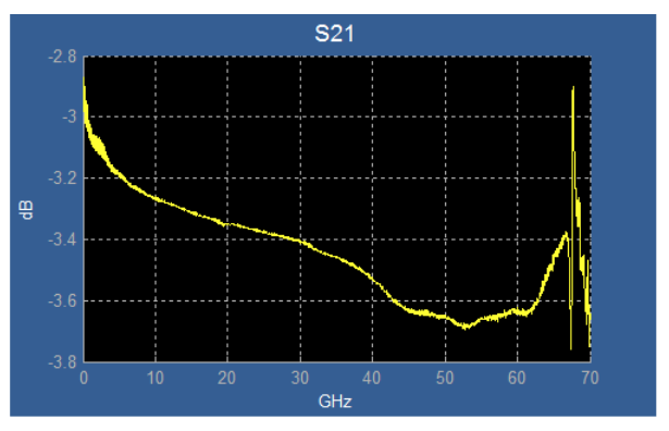
This insertion loss data was generated using a Vector Network Analyzer, but there are several ways to get the performance data. In some cases, the vendor of the attenuator will provide it with the part. It is also possible to use Time Domain Network Analysis techniques with a fast TDR step pulse source to produce the data. Once you have this data, the next step is to create a correction filter that can be applied to the signal that is connected to this attenuator, so that the calibration is correct. The filter can be created in a variety of ways, but perhaps the easiest way on a Tektronix oscilloscope is to use the Tek Serial Data Link Analysis (SDLA) Visualizer tool. This is an option that can be run on the scope, which will read in the S2P file and produce a correction filter that compensates for the deviations of the attenuator from the ideal value.
Attenuator Values
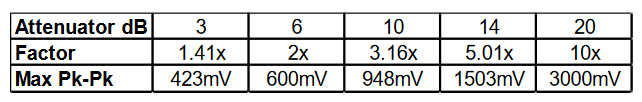
The value of attenuator an engineer chooses to apply should be the minimum required to support the display of the full signal swing (no clipping). Here is a chart that provides a list of the common attenuators available, and the resulting increase in Pk-Pk range, based on a 300mVFS un-attenuated range:
Effects of Attenuators on Frequency Response
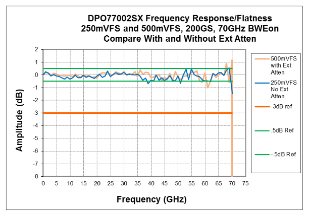
The following plot shows the comparison of the frequency response of the DPO77002SX with the gain set to 250mVFS, and with a 6dB attenuator (2x) applied. While there are some very small variations, the performance is quite consistent between the two plots. There is no significant impact on frequency response, provided that the de-embed of the attenuator has been properly applied, using a tool like Tek’s Serial Data Link Analysis Visualizer.
Noise Topics
Often questions arise about noise performance relative to external attenuator de-embedding. The fact is that essentially the same process occurs whether you are compensating for internal attenuators or external attenuators. The correction (DSP) that is used is boosting or attenuating the signal to provide a flat overall response in the scope system. If DSP boosting is done, it has the effect of increasing noise at the same time that it increases the signal of interest. However, keep in mind that this source of noise is in addition to the noise generated from switch contacts, and that the losses associated with the switches and bypass paths will also result in additional boosting for those scopes that have internal attenuation.
The following is a comparison of the baseline (no signal applied) noise performance of the Tektronix DPO77002SX 70GHz scope and the Keysight DSAZ634A 63GHz scope, with both instruments set to 60GHz bandwidth for a fair comparison.
This plot shows that the Tek scope is providing lower noise performance overall, and as much as 27% lower at some settings.
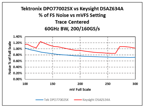
This range shown is the full dynamic range of the Tek preamp. This means that there are no external attenuators involved in this measurement, but the “bumps” in the trace of the Keysight scope indicate the points where attenuation switches are occurring on their scope.
Next, let’s look at an extended plot, which shows a similar noise plot, but with external attenuators added to the Tek scope as needed to meet the dynamic range requirements. In each case, the associated de-embed filter is applied to the measured channel to correct for the attenuator imperfections, and therefore any impact on the noise performance due to the addition of the attenuators would be see. Here is the plot:
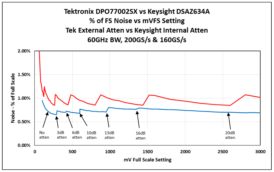
In this example, we started with no attenuation, then added a single 3dB attenuator, then removed that and added a 6dB attenuator, then removed that and added a 10dB attenuator. At the 13dB point, we combined the 3dB and the 10dB. Likewise, we combined the 10dB and the 6dB to get a total of 16dB attenuation. Finally, at the 20dB point, we used a single 20dB attenuator. As you can see, the noise performance remained exceptionally low throughout the entire extended dynamic range.
Summary
From this discussion, you have seen that it is possible to maintain outstanding signal fidelity while using external attenuators with the DPO70000SX series scopes. One of the premises behind the decision to use the external attenuator approach is that most applications have a relatively narrow range of amplitudes that are routinely encountered during measurements, and that once the system has been set up for a specific range, the system is likely to remain configured that way for long periods.