The world is currently experiencing an explosive growth in the amount of data being generated. This is a trend expected to accelerate as new technologies are implemented at wider scales. Prime examples include the next generation of wireless communication in the form of 5G, the expanding fields of artificial intelligence and machine learning, the Internet of Things (Iot), cryptocurrency, virtual reality, and even fields such as the automotive industry. Throughout 2021, it is expected that 44 trillion gigabytes of data (44 zettabytes) will be generated. It’s estimated that 1.7MB of data will be created every second for every person on earth1. This massive amount of data needs to be stored, accessed, and analyzed at faster speeds than ever—requiring systems with greater bandwidth, storage density, and overall performance.
FASTER MEMORY NEEDED TO DRIVE PERFORMANCE
As a counterpart to increased data generation, performance increases have been demanded of memory to store, transfer, and manipulate all this information. A major bottleneck of this process is the speed at which memory can access and transfer data. Slower memory access times can cause a drag on overall system performance, and the data throughput itself is limited by the memory’s transfer rate. A historically dominant form of high performance, quick access memory, has been Double Data Rate Synchronous Dynamic Random Access Memory (DDR SDRAM). Originally introduced as a standard in the 1990s, it developed extremely quickly, with 2014 introducing the fourth generation of the standard – DDR4. DDR4 is a memory interface that initially operated at data transfer rates of 1600 MT/s, eventually reaching speeds of 3200 MT/s as the standard reached maturity. While this was sufficient when computer processors had only eight cores, the introduction of multi-core processors using between 28 and 64 cores today (and promises of 80 and 96 cores on the horizon) make it clear that moving forward we need higher memory performance than what DDR4 can provide.
To help meet this need, the industry is transitioning from DDR4 to the next generation of the DDR memory standard – DDR5. DDR5 is poised to become a dominant and fast-growing successor to its previous iterations. Picking up where DDR4 left off, DDR5 will initially provide transfer speeds of 3,200 MT/s, up to 6,400 MT/s, and is predicted to scale all the way up to 8,400 MT/s in the future.
THE CUSTOMER CHALLENGE
DDR5 introduces a whole set of new challenges that must be overcome in its implementation and verification. Higher data rates have resulted in an expansion of the required test equipment bandwidth, new procedures for measuring jitter that move away from historical methodology, an entirely new element to DDR in the form of receiver equalization, and even the introduction of new standardized tests using fixtures all come together as major challenges in validating DDR5.
THE SOLUTION
TEKTRONIX OSCILLOSCOPES AND TEKEXPRESS DDR TX SOFTWARE
The improved performance DDR5 brings in turn means that higher performance equipment is required to analyze and test DDR5 enabled devices. Answering this performance demand, Tektronix has developed an in-depth solution leveraging the hardware of high bandwidth oscilloscopes and probes such as the DPO71604SX and P7716, in conjunction with an entirely new software automation platform.
The Tektronix TekExpress DDR Transmitter (Tx) software is an automated test application designed to validate and debug DDR5 devices based on the parameters defined in the JEDEC (Joint Electron Device Engineering Council) specification. The Tektronix option DDR5SYS (TekExpress DDR Tx) includes full test coverage and multiple debugging tools for the following:
- DRAM components
- Data Buffer/RCD components
- System boards
- Embedded systems
- Servers and Client/Desktop
TekExpress DDR Tx supports the measurement of over 50 DDR5 electrical and timing parameters as per the DDR5 JEDEC specification. Powerful tools are built-in to aid in characterization and debugging such as multi-gating, DDR5 DFE analysis software, and a user defined acquisition mode that provides full user-control over test conditions.
The Tektronix TekExpress DDR Tx solution reduces the effort spent on testing and accelerates the process for DDR systems and devices with several unique and innovative capabilities. TekExpress DDR Tx provides a simple, step-by-step, and easy-to-use interface to speed up the testing process.
STEPS USED IN TESTING AND MEMORY CIRCUITS
The following steps might be used by customers to verify that their products meet DDR5 specifications:
- A high-impedance Tektronix probe is soldered to the DDR subsystem being tested – allowing access to the electrical signals of interest.
- Tektronix TekExpress DDR Tx Software analyzes the probed signals and compares them to the DDR5 specifications. Additional software running on the oscilloscope can be used to perform a variety of tests such as plotting eye diagrams and measuring relevant electrical parameters.
- At the end of the test, a pass/fail report is generated providing detailed information about the tested device, physical setup, and measured parameters compared with the JEDEC specification.
- If something fails, or unexpected results occur, the TekExpress DDR software solution can be further used to debug the results.
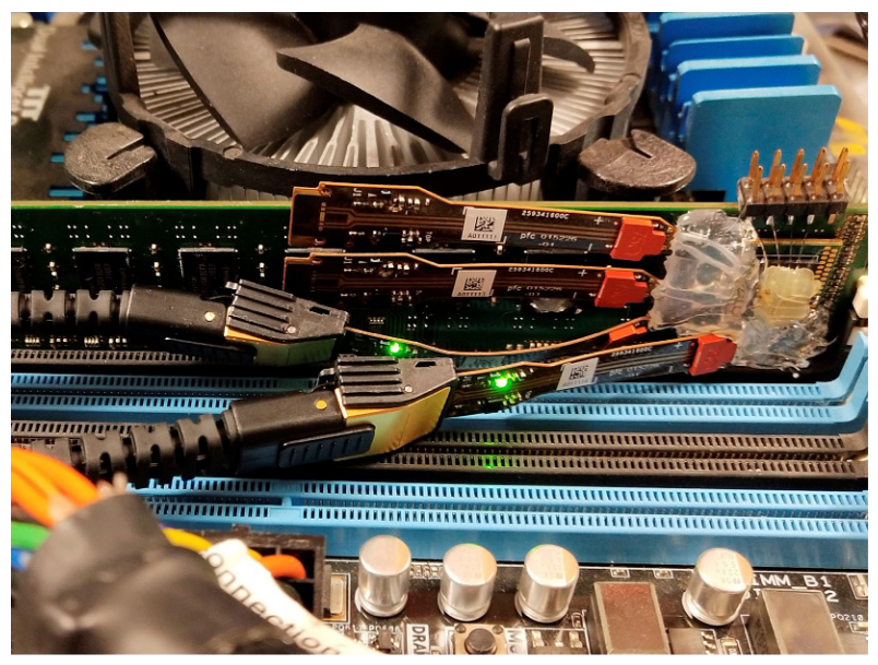
Figure 1 shows an example of a probe accessing a device to perform system level TX testing. In this example, the System on Chip (SOC) is communicating with the device under test (DRAM/RCD/ DB) with bidirectional traffic on the DDR bus. The user accesses the interface by using an interposer soldered underneath the DRAM and probes the interface by using high impedance probe amplifiers. The TekExpress DDR Tx software provides the tools necessary for the measurement of parameters such as clock jitter, read/write timing, and even eye diagrams.
TEKTRONIX SDLA64 USED FOR DFE RECEIVER EQUALIZATION AND SIGNAL DE-EMBED
Increased signaling speeds and shrinking geometries create several challenges for next generation multi-gigabit designs and test methodologies. Smaller form factors make signal access more difficult resulting in nonideal probing points. This can lead to loss and reflections on the acquired signals due to impedance discontinuities that are not present at the ideal measurement location.
The tools previously employed for testing and debugging DDR have become insufficient with the advent of DDR5. With designs exploring higher data rates in conjunction with more stringent loading requirements, accessing the signal unperturbed has become extremely difficult if not impossible. A powerful method for combating these issues is the use of the Tektronix Serial Data Link Analysis (SDLA) software package. Leveraging SDLA’s capability, users can remove the loading effects of the test setup (probes, interposers, cables) through the de-embedding process. Whether it be reflections, insertion loss, cross coupling, or other impairments, SDLA provides powerful capability to effectively analyze your signal as if these effects weren’t present. This can greatly increase the validity and accuracy of measurements taken – and can make the difference between a device passing or failing.
TEKTRONIX DFE ANALYSIS SOFTWARE
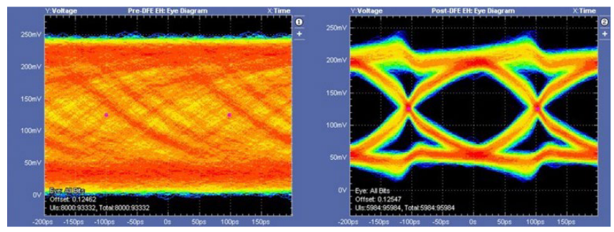
For the first time in DDR, receiver equalization has been introduced in the form of a 4-tap DFE (Decision Feedback Equalization). This creates an additional challenge when accessing and analyzing DDR5 signals. For instance, even after de-embedding, a generated eye diagram may remain closed (Figure 2). To open the eye further, DFE equalization needs to be implemented.
Tektronix has developed tools to help tackle the problems the DFE introduces during testing. SDLA can be used to analyze a continuous stream of data from a device, thereby train the DFE gain and tap values. From there, the DFE characteristics can be used as an input into the TekExpress DDR Tx automation software to generate eye diagrams on bursty signals after the DFE has been applied. There’s also the capability to use a standalone DFE application (included with TekExpress DDR Tx) which allows a user to manually generate and view DDR signals after DFE equalization has been applied outside the automation framework.
JITTER NOISE FLOOR CALIBRATION
DDR5 has new Rj/DJ jitter measurements for CLK, DQS and DQ. In addition, Rj specs are (very tight) in the 0.5ps range. Tektronix has developed a new Jitter Noise Floor Noise Calibration that can be accessed directly on a Tektronix oscilloscope. The tool provides the option to include probes, probe tips and de-embedding filter files during noise calibration to account for the extra noise generated or amplified. The tool includes full integration with the oscilloscope analysis software (DPOJET) to remove the scope’s noise jitter from measurement results.
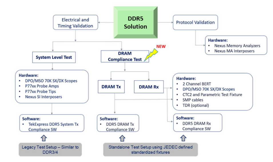
TEKTRONIX PRODUCTS USED IN DDR5 TESTING
The following figure summarizes the products used as part of the Tektronix DDR5 solution.
CONCLUSION
With the industry transitioning into DDR5 development, testing, and production, new hardware and software tools are required to address the newest challenges that testing DDR5 brings. Tektronix has developed a line of high bandwidth oscilloscopes and probes to acquire signals from DDR5 devices, and powerful software tools for validation. As a sample, we encourage you to visit Tek.com and while you are there learn more about our solutions, watch a video demonstration or a webinar on DDR5 and the Tektronix solution.