As modern electronics continue to shrink, researchers increasingly look to nanotechnology for breakthroughs in device size and power consumption. In these nanoscale devices, electrical characteristics are affected by quantum behavior. For example, device resistance typically is not constant, and no single I-V measurement can characterize it. For nanoscale devices, detailed measurements at many points are needed to generate a valid I-V curve, and plot differential conductance (dG = dI/dV).
Who Uses Differential Conductance?
Differential conductance measurements are performed in many areas of research, though sometimes under different names. Table 1 lists some of these applications
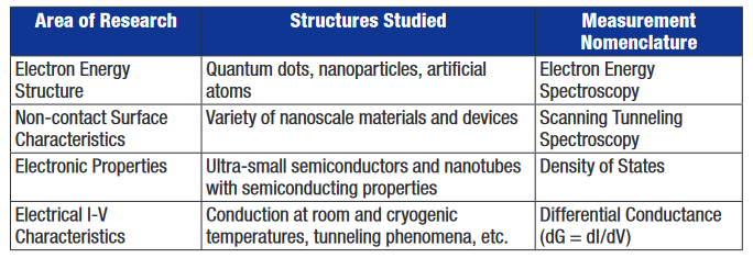
The fundamental reason for these studies is that device conductance reaches a maximum at voltages where electrons are most active. Thus, dI/dV is directly proportional to the density of states and is the most direct way to measure it.
Existing Methods of Measuring Differential Conductance
While there is no standardized technique for obtaining differential conductance, almost all approaches follow one of two methods:
(1) Perform a current-voltage sweep (I-V curve) and take the mathematical derivative, or
(2) Superimpose a low amplitude AC sine wave on a stepped DC bias; then use a lock-in amplifier to obtain the AC voltage across the DUT (device under test) and the AC current through it.
I-V Technique - The I-V sweep technique has the advantage of being easier to set up and control. It only requires one source and one measurement instrument, which makes it relatively easy to coordinate and control. The fundamental problem is that even a small amount of noise becomes a large noise when the measurements are differentiated.
AC Technique - The problem with this method is that, while it provides a marginal improvement in noise, it imposes a large penalty in terms of system complexity. A typical equipment list includes:
- AC voltage source or function generator
- DC bias source
- Series resistor or coupling capacitor to mix AC and DC signals
- Lock-in amplifier synchronized to the sources to facilitate low-level measurements
Separate instruments to measure AC and DC voltage and current
sive time and knowledge of electrical circuitry. Trial and error methods may be required to determine the series resistor and coupling capacitor values based on the unknown DUT impedance and response frequency. Long cabling, such as that used in attaching a device in a cryostat, reduces usable frequency and increases noise. In addition, multiple instruments are susceptible to problems of ground loops and common mode current.
Simple, Low-Noise Solution
Fortunately, there is a new technique for differential conductance measurements that is easy to use and provides low-noise results. This improved method uses a fourwire, source current/measure voltage methodology. It requires a precision instrument that combines the DC and AC source components (stimulus), and a nanovoltmeter for the response measurements. Until recently, a single instrument to supply a precise AC signal over a DC bias was not commercially available. However, these features are now contained in the Keithley Models 6220/6221 Current Sources. Keithley's Model 2182A Nanovoltmeter can be used for the voltage measurements.
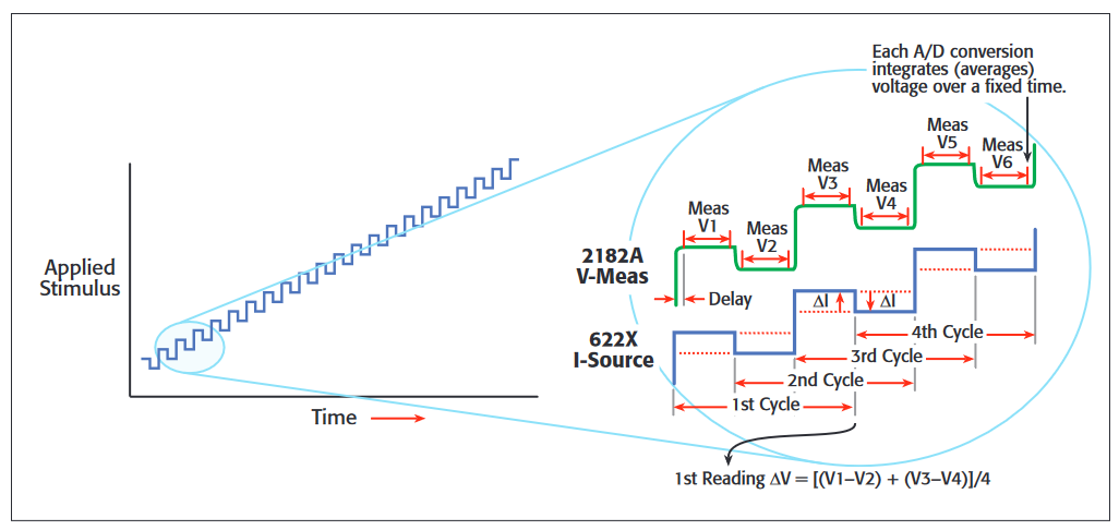
With these instruments, an AC current is superimposed on a linear staircase sweep. The amplitude of the alternating portion of the current is the differential current, dI (Figure 1). The current source is synchronized with the nanovoltmeter by using a Trigger Link cable. After measuring the voltage at each current step, the nanovoltmeter calculates the delta voltage between consecutive steps. Each delta voltage is averaged with the previous delta voltage to calculate dV. Differential conductance, dG, is derived from dI/dV.
Benefits of the Four-Wire, Source I/Measure V Method
The new method provides low noise results at least 10 times faster than previous methods. Only two instruments and a single sweep are required. When user-defined currents are small, the performance of instrumentation described above cannot be duplicated by any user-assembled system in terms of source accuracy, noise, and guarded measurements (the latter being used to reduce DC leakage and improve system response time). AC current can be sourced accurately, even below 10pA. The nanovoltmeter has a sensitivity superior to lock-in amplifiers, low 1/f noise, and automatically compensates for offsets and drift. The four-wire connections eliminate voltage drop errors due to lead or contact resistance, because there is no current flowing through sense leads. This is important when the DUT has regions of low or moderate impedance.
Another key benefit is that more data points can be collected in areas of highest conductance (i.e., areas of greatest interest) by sourcing the sweep in equal current steps. Because of the instrumentation's inherently low source and measurement noise, only one pass is required, shortening data collection time from hours to minutes. Furthermore, the instruments' active guard eliminates the slowing effects of cable capacitance, greatly improving device settling time, measurement speed, and accuracy
Special Cases
Some devices have non-monotonic I-V curves. This behavior is classified as follows:
(1) Current Hop – A given voltage may correlate to more than one possible current.
(2) Negative Differential Conductance (NDC) – A given current may correlate to more than one possible voltage.
With a slight modification, the source current/measure voltage differential conductance method can be used with devices that exhibit these behaviors. This technique is covered in more detail in a white paper titled “An Improved Method for Differential Conductance Measurements,” which is available at http://www.keithley.com/ data?asset=50074.
Conclusions
With appropriate instrumentation, the four-wire source current/measure voltage method is a great improvement over older differential conductance measurements, which are slow, noisy, and complex. The new technique's single sweep shortens hours of data collection to a few minutes, while improving accuracy. Equipment cost is also reduced, since only two instruments are required, instead of six or more.
Precision AC/DC Current SourceNanovoltmeter Combo Improves Speed and Accuracy of Nanotech Measurements
Keithley's Model 6221 is an AC and DC Current Source with a Current Source Waveform Generator. As the only commercially available AC current source, it now eliminates the need for researchers and engineers to build their own instrumentation. By combining the Model 6221 with the Keithley Model 2182A Nanovoltmeter, rapid measurement and characterization of nanoscale devices and materials are easily accomplished. This can be done at very low source currents levels with great preci sion and without sacrificing accuracy in the lower—and harder to measure—voltages across the sample. Consequently, the Model 6221/2182A combination can measure resistances from 10nohm to 1Gohm, including delta mode measurements that improve accuracy by up to 1000 times. Used in this way, the Model 6221 acts as a high performance alternative to AC resistance bridges and lock-in amplifiers, and is especially useful in differential conductance measurements for characterizing semiconductor and nanotechnology devices
The Model 6221 can be programmed for pulse widths as short as 50 microseconds, and supports pulsed I-V measurements. It can source AC currents from 2pA to 100mA and DC currents from 100fA to 100mA with a 10MHz output update rate. The built-in standard and arbitrary waveform generator has a frequency range of 1mHz to 100kHz. The user can define current ramps and program the unit to step through predefined sequences of up to 64,000 output values using a trigger or a timer. Linear, logarithmic, and custom sweeps are supported. Programming can be done from the front panel controls or from an external controller via RS-232, GPIB, or Ethernet interface. Included control software simplifies setup and operation.