XYZ's of Oscilloscopes

How to use an oscilloscope
Once you have an oscilloscope, there are basic things you need to do to set it up and begin using it. This chapter briefly describes how to use an oscilloscope. In particular, proper grounding is very important for safety reasons; not just for yourself but also for the integrated circuits (ICs) you are testing. Setting oscilloscope controls, calibrating the oscilloscope, connecting oscilloscope probes, and compensating the probes are also described, along with basic oscilloscope measurement techniques.
Proper Grounding
Proper grounding is an important step when you set up to take measurements or work on a circuit:
- Properly grounding the oscilloscope protects you from a hazardous shock.
- Properly grounding yourself protects your ICs from damage.
To ground the oscilloscope means to connect it to an electrically neutral reference point, such as earth ground. Ground your oscilloscope by plugging its three-pronged power cord into an outlet grounded to earth ground. Grounding the oscilloscope is necessary for safety. If a high voltage contacts the case of an ungrounded oscilloscope—any part of the case, including knobs that appear insulated—it can give you a shock. However, with a properly grounded oscilloscope, the current travels through the grounding path to earth ground rather than through you to earth ground.
Grounding is also necessary for taking accurate measurements with your oscope. The oscilloscope needs to share the same ground as any circuits you are testing. Some oscilloscopes do not require separate connection to earth ground. These oscilloscopes have insulated cases and controls, which keeps any possible shock hazard away from the user.
If you are working with ICs, you also need to ground yourself. ICs have tiny conduction paths that can be damaged by static electricity that builds up on your body. You can ruin an expensive IC simply by walking across a carpet or taking off a sweater and then touching the leads of the IC. To solve this problem, wear a grounding strap, as shown in Figure 64. This strap safely sends static charges on your body to earth ground.
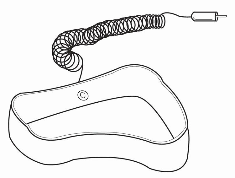
Figure 64: Typical wrist-type grounding strap.
Setting the Controls
After plugging in the oscilloscope, take a look at the front panel. As described at the beginning of Chapter 4—Oscilloscope Systems and Controls, the front panel is typically divided into three main sections labeled vertical, horizontal, and trigger. Your oscilloscope may have other sections, depending on the model and type. Notice the input connectors on your oscilloscope—this is where you attach the probes. Most oscilloscopes have at least two input channels and each channel can display a waveform on the screen. Multiple channels are useful for comparing waveforms. The front panel of a Mixed Signal Oscilloscope (MSO) will also have digital inputs.
Some oscilloscopes have AUTOSET and/or DEFAULT buttons that can set up the controls in one step to accommodate a signal. If your oscilloscope does not have this capability, it is helpful to set the controls to standard positions before taking measurements.
Oscilloscope Instructions
- Set the oscilloscope to display channel 1.
- Set the vertical volts/division scale and position controls to mid–range positions.
- Turn off the variable volts/division.
- Turn off all magnification settings.
- Set the channel 1 input coupling to DC.
- Set the trigger mode to auto.
- Set the trigger source to channel 1.
- Turn trigger holdoff to minimum or off.
- Set the horizontal time/division and position controls to mid-range positions.
- Adjust channel 1 volts/division such that the signal occupies as much of the 10 vertical divisions as possible without clipping or signal distortion.
Calibrating the Instrument
In addition to proper oscilloscope setup, periodic instrument self-calibration is recommended for accurate measurements. Oscilloscope calibration is needed if the ambient temperature has changed more than 5° C (9° F) since the last self-calibration or once per week. In the oscilloscope menu, this can sometimes be initiated as Signal Path Compensation. Refer to the manual that accompanied your oscilloscope for more detailed instructions.
Connecting the Probes
Once you have properly grounded the oscilloscope and yourself, and you’ve set up the oscilloscope in standard positions, you are ready to connect a probe to your oscilloscope. A probe, if well-matched to the oscilloscope, enables you to access all of the power and performance in the oscilloscope and will ensure the integrity of the signal you are measuring. Measuring a signal requires two connections:
- The probe tip connection
- The ground connection
Probes often come with a clip attachment for grounding the probe to the circuit under test. In practice, you attach the grounding clip to a known ground in the circuit, such as the metal chassis of a product you are repairing, and touch the probe tip to a test point in the circuit.
Compensating the Probes
Passive attenuation voltage probes must be compensated to the oscilloscope. Before using a passive probe, you need to compensate it to balance its electrical properties to a particular oscilloscope. You should get into the habit of compensating the probe every time you set up your oscilloscope. A poorly adjusted probe can make your measurements less accurate. Figure 65 illustrates the effects on a 1 MHz test signal when using a probe that is not properly compensated.
Most oscilloscopes have a square wave reference signal available at a terminal on the front panel used to compensate the probe. General instructions to compensate the probe are as follows:
- Attach the probe to a vertical channel.
- Connect the probe tip to the probe compensation, i.e. square wave reference signal.
- Attach the ground clip of the probe to ground.
- View the square wave reference signal.
- Make the proper adjustments on the probe so that the corners of the square wave are square.
Oscilloscope Measurement Techniques
The two most basic oscilloscope measurements you can make are:
- Voltage measurements
- Time measurements
Just about every other measurement is based on one of these two fundamental techniques.
This section discusses methods for how to use your oscilloscope to take measurements visually with the oscilloscope screen. This is a common technique with analog instruments, and also may be useful for “at-a-glance” interpretation of digital oscilloscope displays.
Note that most digital oscilloscopes include automated measurement tools that simplify and accelerate common analysis tasks, thus improving the reliability and confidence of your measurements. However, knowing how to make measurements manually as described here will help you understand and check the automatic measurements.
Voltage Measurements
Voltage is the amount of electric potential, expressed in volts, between two points in a circuit. Usually one of these points is ground (zero volts), but not always. Voltages can also be measured from peak-to-peak. That is, from the maximum point of a signal to its minimum point. You must be careful to specify which voltage you mean. The oscilloscope is a voltage-measuring device. Once you have measured the voltage, other quantities are just a calculation away. For example, Ohm’s law states that voltage between two points in a circuit equals the current times the resistance. From any two of these quantities you can calculate the third using the formula shown below.

Voltage = Current x Resistance
Another handy formula is the power law, which states that the power of a DC signal equals the voltage times the current. Calculations are more complicated for AC signals, but the point here is that measuring the voltage is the first step toward calculating other quantities. Figure 66 shows the voltage of one peak (Vp) and the peak-to-peak voltage (Vp–p).
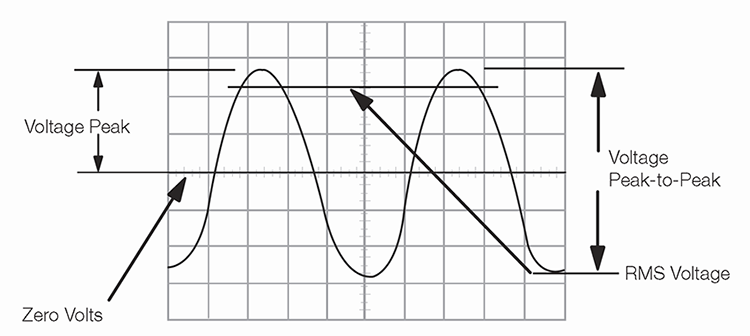
Figure 66: Voltage peak (Vp) and peak-to-peak voltage (Vp-p).
The most basic method of taking voltage measurements is to count the number of divisions a waveform spans on the oscilloscope’s vertical scale. Adjusting the signal to cover most of the display vertically makes for the best voltage measurements, as shown in Figure 67. The more display area you use, the more accurately you can read the measurement.
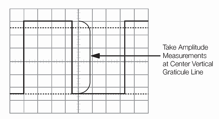
Figure 67: Measure voltage on the center vertical graticule line.
Many oscilloscopes have cursors that let you make waveform measurements automatically, without having to count graticule marks. A cursor is simply a line that you can move across the display. Two horizontal cursor lines can be moved up and down to bracket a waveform’s amplitude for voltage measurements, and two vertical lines move right and left for time measurements. A readout shows the voltage or time at their positions.
Time and Frequency Measurements
You can make time measurements using the horizontal scale of the oscilloscope. Time measurements include measuring the period and pulse width of pulses. Frequency is the reciprocal of the period, so once you know the period, the frequency is one divided by the period. Like voltage measurements, time measurements are more accurate when you adjust the portion of the signal to be measured to cover a large area of the display, as illustrated in Figure 68.
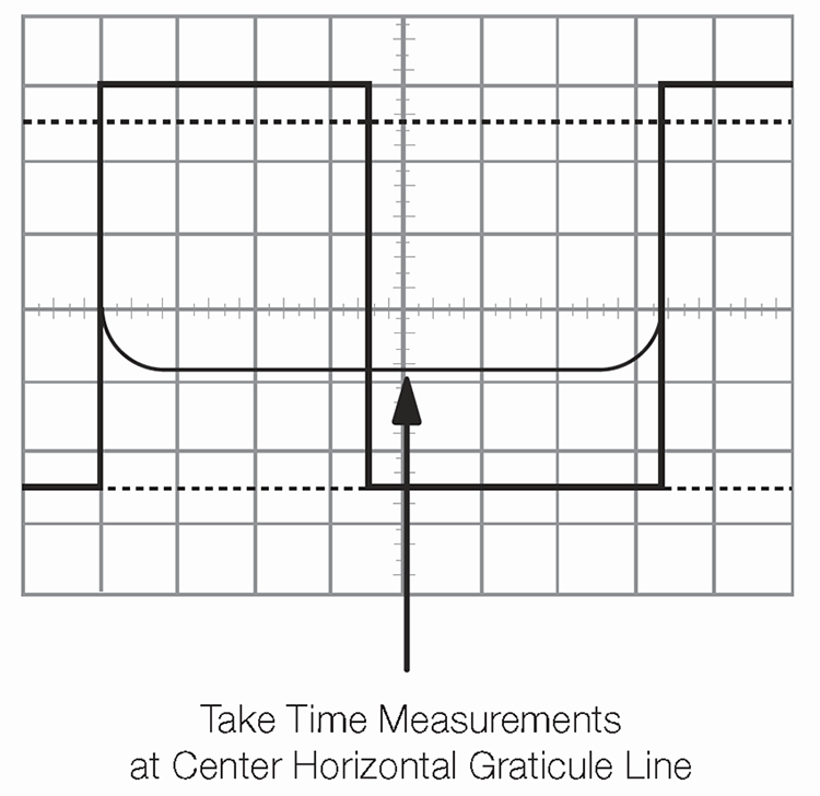
Figure 68: Measure time on the center horizontal graticule line.
Pulse Width and Rise Time Measurements
In many applications, the details of a pulse’s shape are important. Pulses can become distorted and cause a digital circuit to malfunction, and the timing of pulses in a pulse train is often significant.
Standard pulse measurements are pulse rise time and pulse width. Rise time is the amount of time a pulse takes to go from a low to high voltage. By convention, the rise time is measured from 10% to 90% of the full voltage of the pulse. This eliminates any irregularities at the pulse’s transition corners.
Pulse width is the amount of time the pulse takes to go from low to high and back to low again. By convention, the pulse width is measured at 50% of full voltage. Figure 69 illustrates these measurement points.
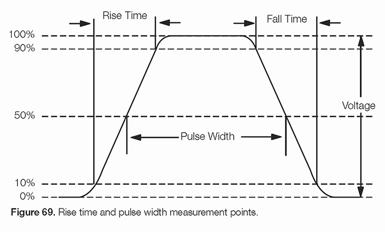
Figure 69: Rise time and pulse width measurement points.
Pulse measurements often require fine-tuning the triggering. To become an expert at capturing pulses, you should learn how to use trigger hold-off and how to set the digital oscilloscope to capture pre-trigger data, as described in Chapter 4—Oscilloscope Systems and Controls. Horizontal magnification is another useful feature for measuring pulses, since it allows you to see fine details of a fast pulse.
Learn more about how to use an oscilloscope in the Oscilloscope Learning Center and download our Oscilloscope Fundamentals poster—with step-by-step instructions for setting up your oscilloscope—to hang in your lab. If you haven’t purchased your oscilloscope or are looking to upgrade to run more advanced tests, shop Tektronix oscope today.