Introduction
To measure the leakage current or insulation resistance of a device, you need to apply a fixed voltage to the device and measure the resulting current. Depending on the device under test, the measured current is typically very small, usually less than 10nA.
This application consists of two examples that demonstrate:
- How to use the Model 2450 to perform leakage current measurements on a capacitor
- How to use the Model 2450 to measure insulation resistance between the two conductors of a coaxial cable
The only difference between these two application examples is that when you measure leakage current, the results are returned in units of amperes. When you measure insulation resistance, the results are returned in units of ohms.
The leakage current application applies the voltage for a specified period because the device needs time to charge. In some cases, the resulting current is measured the entire time the device is biased. In other cases, only one reading is made at the end of the soak period.
The following topics describe how to do these applications from the front panel. They also show how to do them using a remote interface with SCPI commands or Test Script Processor (TSP®) commands.
Equipment required
- One Model 2450 Interactive SourceMeter® instrument
- Two triaxial cables
- One capacitor for the leakage current application
- One coaxial cable or other device for the insulation resistance application
- One ethernet, GPIB, or USB cable for the TSP and SCPI remote command examples
Set up remote communications
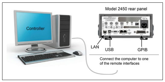
You can run this application from the front panel or any of the supported communication interfaces for the instrument (GPIB, USB, or ethernet).
The following figure shows the rear-panel connection locations for the remote communication interfaces.
Device connections
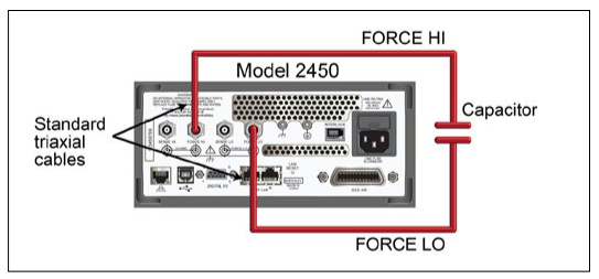
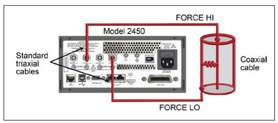
Depending on the device under test (DUT), the current measurement is typically very small, usually <10nA. Measuring leakage current and insulation resistance involves measuring very small values. To get more accurate readings, connect the DUT to the Model 2450 rear panel with low-noise triaxial cables.
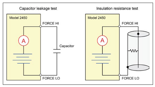
Connect the DUT between the FORCE HI and FORCE LO terminals of the Model 2450.
Figure 2 shows schematic diagrams. One shows measuring the leakage current of a capacitor. The other shows measuring the insulator resistance between two conductors of a coaxial cable.
The following figures show the rear-terminal connections to the device under test (DUT) for these applications. If capacitor leakage measurements are noisy, you may need to use the high capacitance mode or add a low leakage forward-biased diode in series with the capacitor.
Measuring leakage current
The following application demonstrates how to use the Model 2450 to measure the leakage current of a 1nF capacitor by sourcing a voltage and measuring the resulting current using the front panel or over the remote interface. The remote interface examples show SCPI commands and TSP commands.
This application sets the Model 2450 to source 20V and measure the resulting leakage current as a function of time. The instrument takes current measurements for a specific period.
For this test, you will:
- Reset the instrument.
- Set the instrument to read the rear terminals.
- Select the source voltage function and measure current function.
- Set the magnitude of the voltage source.
- Turn on autoranging.
- Set the measure delay.
- Use the Duration Loop trigger model template to make readings for a specified time period.
- Turn on the source output.
- Take readings for a specified period of time.
- Turn off the source output.
NOTE: When you use the Model 2450 to measure small current values, ensure that the device under test is electrostatically shielded. If the capacitor rating is greater than 20nF, enable the high capacitance mode for best results.
For more information about making optimized capacitor leakage measurements and minimizing noisy measurements, see the Keithley Instruments Low Level Measurements Handbook, available on the Keithley Instruments website (http://www.keithley.com)
Set up the leakage current application using the front panel
To set up the application from the front panel:
- Use the test leads to make the connection from the capacitor to the rear panel of the Model 2450, as described in Device connections.
- Reset the Model 2450.
- Press the MENU key.
- Under System, select Manage.
- Select System Reset, and then select OK.
- Press the TERMINAL FRONT/REAR switch to set the instrument to use the rear-panel terminals (R is displayed to the left of the switch).
- Press the HOME key.
- Press the FUNCTION key.
- Under Source Voltage and Measure, select Current.
- Select the button next to Source (at the bottom of the screen).
- Enter 20 V and select OK.
- Press the MENU key.
- Under Trigger, select Templates.
- Next to Templates, select Duration Loop.
- Next to Duration, enter a soak time of 30s and select OK.
- Next to Delay, enter 0.2s, and select OK.
- Press the HOME key to return to the Home screen.
- Press the TRIGGER key to turn on the output and make measurements. The output is turned off when the measurements are complete.
View the measurements on the front-panel graph
To view the leakage current measurements on the front-panel graph:
- Press the MENU key.
- Under Views, select Graph.
- Select the Scale tab.
- Under Y-Axis, next to Scale Format, select Log.
- Under X-Axis, next to Auto Scale, select On.
- Select the Graph tab to view the graph.
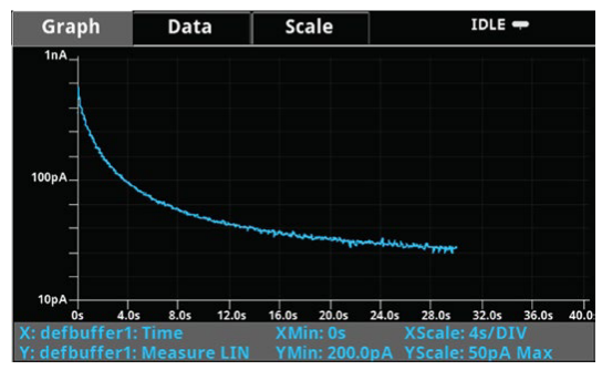
Figure 5 shows the front-panel graph for this application.
Set up the leakage current application using SCPI commands
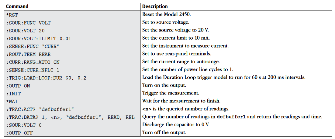
The following SCPI code performs a capacitor leakage measurement by sourcing 20V and measuring the resulting leakage current.The Duration Loop trigger model template applies the voltage for 60 seconds and makes measurements at 200ms intervals. After the duration time, the capacitor is discharged at 0V and the output is turned off.
Send the following commands for this example application:
Set up the leakage current application using TSP commands
NOTE: The following TSP code is designed to be run from Keithley Instruments Test Script Builder (TSB). TSB is a software tool included on one of the CD-ROMs that came with your Model 2450. You can install and use TSB to write code and develop scripts for TSP-enabled instruments. Information about how to use TSB is in the online help for TSB and in the "Introduction to TSP operation" section of the Model 2450 Reference Manual.
To use other programming environments, you may need to make changes to the example TSP code.
By default, the Model 2450 is configured to use the SCPI command set. You must select the TSP command set before sending TSP commands to the instrument.
To enable TSP commands:
- Press the MENU key.
- Under System, select Settings.
- Select the button next to Command Set and select TSP.
- You are prompted to reboot. Select Yes.
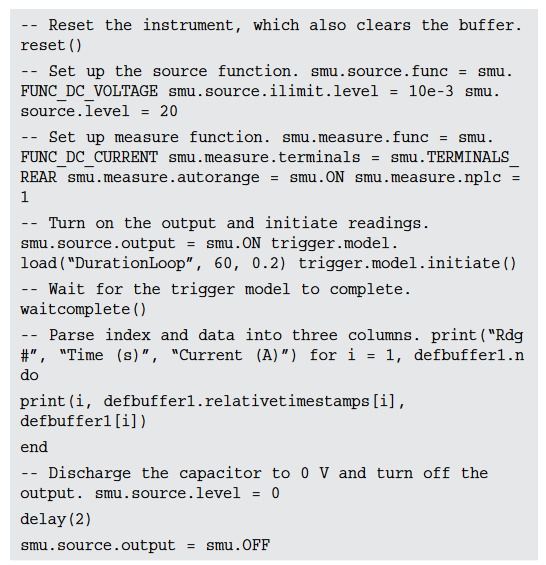
The following TSP code performs a capacitor leakage measurement by sourcing 20V and measuring the resulting leakage current. The Duration Loop trigger model template applies the voltage for 60 seconds and makes measurements at 200ms intervals. After the duration time, the capacitor is discharged at 0V and the output is turned off.
After the code is executed, the measurement results are displayed in the Instrument Console of Test Script Builder.From the Instrument Console, you can copy the data into a spreadsheet for graphing.
Send the following commands for this example application:
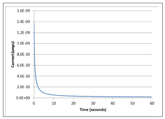
The graph in the Figure 6 shows the results of this application. Notice the exponential current response of the capacitor as it charges up to 20 V over time.
Measuring insulation resistance
The following applications demonstrate how to use the Model 2450 to measure insulator resistance. The applications shows how to use the front-panel interface, the remote interface using the SCPI command set, and the remote interface using the Test Script Processor (TSP®) command set.
You make insulation resistance measurements between traces on a printed circuit board and between conductors in cables and connectors.
This application sets the Model 2450 to source 20 V and makes 10 resistance readings with a 100 ms interval time. Once the measurements are made, the output is turned off.
For this test, you will:
- Reset the instrument
- Set the instrument to read the rear terminals
- Select the source voltage function and measure resistance function
- Set the magnitude of the voltage source output
- Turn on autoranging
- Use the Simple Loop trigger model template to set the numbers of readings and interval time
- Turn on the source output
- Make readings
- Turn off the source output
Set up the insulation resistance application using the front panel
To set up the application from the front panel:
- Connect the device under test (DUT) to the rear panel of the Model 2450, as described in Device connections.
- Reset the Model 2450.
- Press the MENU key.
- Under System, select Manage.
- Select System Reset, and then select OK.
- Press the TERMINAL FRONT/REAR switch to set the instrument to use the rear-panel terminals (R is displayed to the left of the switch).
- Press the HOME key.
- Press the FUNCTION key.
- Under Source Voltage and Measure, select Resistance.
- Select the button next to Source (at the bottom of the screen).
- Enter 20 V (or other applicable test voltage) and select OK.
- Press the MENU key.
- Under Trigger, select Templates.
- Next to Templates, select SimpleLoop.
- Set Count to 10 and select OK.
- Set Delay to 0.1 seconds and select OK.
- Press the HOME key.
- Press the OUTPUT ON/OFF switch to enable the output.
- Press the TRIGGER key to begin taking readings. The resistance measurements appear in the measure area (top half) of the Home screen.
- Press the OUTPUT ON/OFF switch to turn off the output when you are done making measurements.
Viewing the measurements on the front-panel graph
To view the insulation resistance measurements on the front-panel graph while the output is on:
- Press the MENU key.
- Under Views, select Graph.
Set up the application using SCPI commands
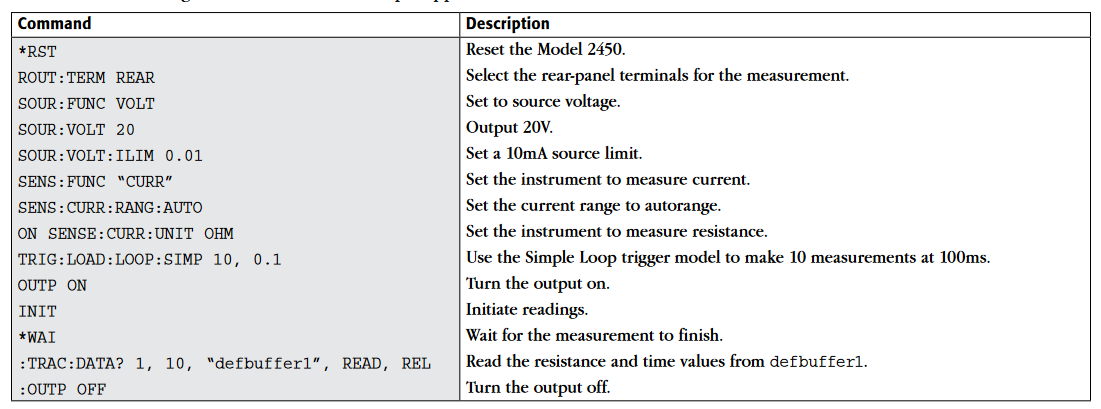
The following SCPI commands make insulation resistance measurements by sourcing 20V and measuring the resistance. The Simple Loop trigger model template is used to make 10 measurements at 100ms intervals.
Send the following commands for this example application:
Set up the application using TSP commands
NOTE: The following TSP code is designed to be run from Keithley Instruments Test Script Builder (TSB). TSB is a software tool included on one of the CD-ROMs that came with your Model 2450. You can install and use TSB to write code and develop scripts for TSP-enabled instruments. Information about how to use TSB is in the online help for TSB and in the “Introduction to TSP operation” section of the Model 2450 Reference Manual.
To use other programming environments, you may need to make changes to the example TSP code.
By default, the Model 2450 is configured to use the SCPI command set. You must select the TSP command set before sending TSP commands to the instrument.
To enable TSP commands:
- Press the MENU key.
- Under System, select Settings.
- Select the button next to Command Set and select TSP.
- You are prompted to reboot. Select Yes.
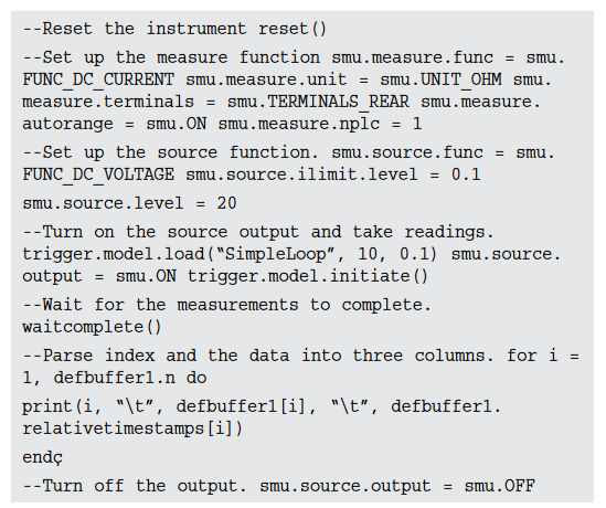
The following TSP commands make insulation resistance measurements by sourcing 20V and measuring the resistance.
The Simple Loop trigger model template is used to make 10 measurements at 100ms intervals. After the code is executed, the measurement results are displayed in the Instrument Console of Test Script Builder.
Send the following commands for this example application: