
Double Pulse Testing for Power
Semiconductor Devices with
an Oscilloscope and Arbitrary
Function Generator
APPLICATION NOTE
Double Pulse Testing for Power Semiconductor Devices
APPLICATION NOTE
with an Oscilloscope and Arbitrary Function Generator
but compact power electronics are desirable across a
Introduction
wide range of products. At the same time, efficiency is
Semiconductor materials used in power electronics are
increasingly important as governments introduce financial
transitioning from silicon to wide bandgap semiconductors
incentives and more stringent energy-efficiency regulations.
such as silicon carbide (SiC) and gallium nitride (GaN) due
to their superior performance in many applications. Wide
When designing power converters, a 0% power loss is ideal
bandgap switching devices enable smaller, faster and more
as illustrated in Figure 1. However, switching losses are
efficient designs. The power-density advantages of smaller
inevitable. So, the goal is to minimize the losses through
and lighter designs are particularly evident in space-
design optimization, and design parameters related to
constrained and mobile products such as electric vehicles,
efficiency must be rigorously measured.
Vin × Iin = Pin
Switching Power
Vout × Iout = Pout
Source
Load
Converter
In ideal (100% efficient) power conversion, PIN = POUT
Figure 1: Ideal power conversion efficiency.
A traditional silicon-based converter might have an efficiency of about 87% to 90%, meaning that 10% to 13% of the input
power is dissipated within the converter, mostly as waste heat. A significant portion of this loss is dissipated in the switching
devices such as MOSFETs or IGBTs. [2]
On-State
VAB × IAB = PDISS
= 0
Off-State
A
B
A
B
IAB
(
VAB
= 0)
VAB
(IAB = 0)
Figure 2: Ideal switching.
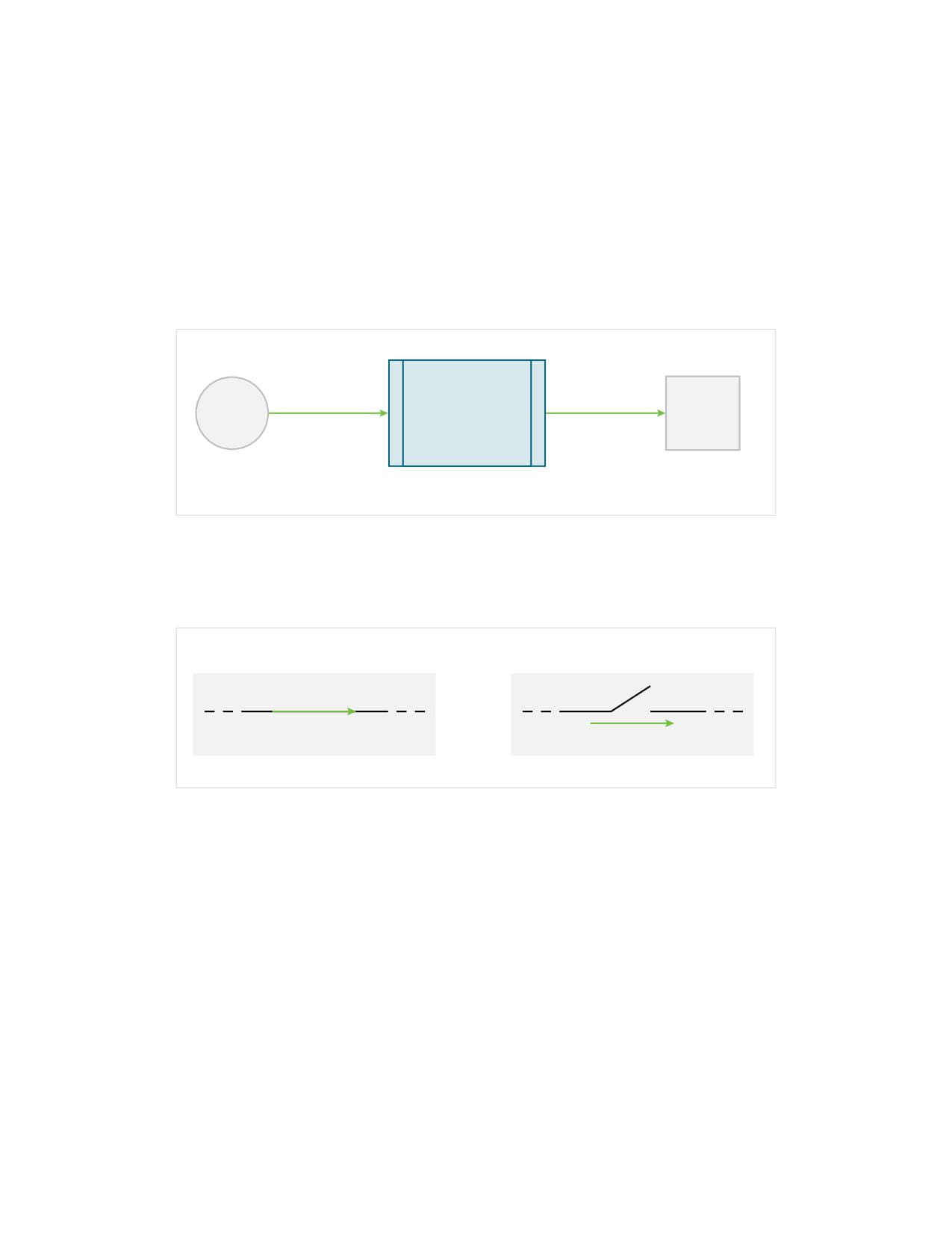
Ideally, the switching device is either “on” or “off” as shown in Figure 2 and instantaneously switches between these states.
In the “on” state, the impedance of the switch is zero ohms and no power is dissipated in the switch, regardless of how much
current is flowing through it. In the “off” state, the impedance of the switch is infinite, and zero current is flowing, so no power
is dissipated.
2 | WWW.TEK.COM
Double Pulse Testing for Power Semiconductor Devices
APPLICATION NOTE
with an Oscilloscope and Arbitrary Function Generator
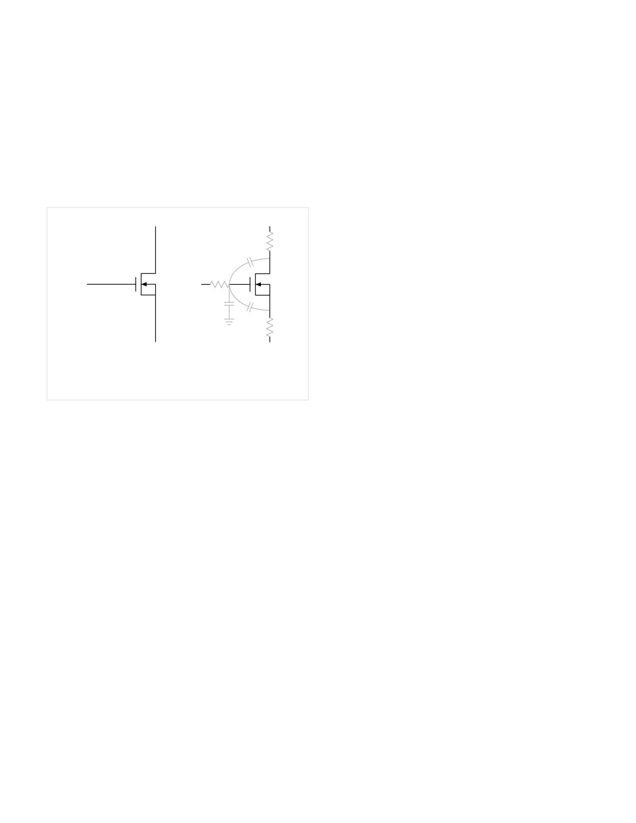
In practice, power is dissipated during the transition
What is Double Pulse Testing?
between “on” and “off” (turn-off) and between “off” and “on”
Double pulse testing (DPT) is a method to measure the
(turn-on). These non-ideal behaviors occur because of
switching parameters and evaluate the dynamic behaviors
parasitic elements in the circuit. The parasitic capacitances
of power devices. It enables engineers to test switching
on the device , shown in Figure 3, slow the switching speed
devices under controlled voltage, current and temperature
of the device, extending the turn-on and turn-off times. [2]
conditions. Pulses are used to limit self-heating of the DUT
In order to keep the switching losses at minimum and thus
and maintain a stable junction temperature. This test is
design more efficient converters, design engineers simulate
performed to:
and measure switch timing and associated energy losses.
• Guarantee specifications of power devices like
MOSFETs and IGBTs.
• Confirm actual value or deviation of power devices or
power modules.
• Measure switching parameters under various load
conditions and validate performance across many
devices. [3]
The goals of this testing are typically to measure the
following switching parameters: [4][5]
•
Turn-on Parameters:
A.
B.
- Turn-on delay, td(on)
How switch
How the
appears on
circuit sees
- VDS fall time , tf
schematic
the switch
- Turn-on time, ton
Figure 3: A: How a MOSFET appears on the schematic. B: How the circuit sees
- Max drain current, ID
the MOSFET.
- dv/dt
- di/dt
Engineers also measure energy loss due to reverse
recovery. This loss is caused by a transient current flowing
- Turn-on energy, Eon
into the switching device as the diode feeding it switches
- Dynamic RDS(on)
from being forward-biased to reverse-biased.
•
Turn-off Parameters:
The preferred test method to measure the switching
- Turn-off delay, td(off)
parameters of MOSFETs or IGBTs is the “Double Pulse Test”
- VDS rise time, tr
method. The test methods are described in JEDEC and IEC
- Turn-off time, toff
standards, including JEP182 [3], JESD24-10, IEC 60747-9,
- Max drain to source voltage, VDSM
IEC 60747-8 and IEC 60747-9.
- dv/dt
This application note will describe double pulse testing
- di/dt
and how it’s implemented using instrumentation. It will
- Turn-off energy, Eoff
cover switching loss and reverse recovery measurements.
In particular, it will explain how to generate pulses with
- Output charge, Qoss
the Tektronix AFG31000 Arbitrary Function Generator and
•
Reverse Recovery Parameters:
measure important parameters with a 4, 5 or 6 Series MSO
- Reverse recovery time, trr
oscilloscope and probes.
- Reverse recovery current, Irr
- Reverse recovery charge, Qrr
- Reverse recovery energy, Err
- di/dt
- Forward on voltage, VSD
WWW.TEK.COM | 3
Double Pulse Testing for Power Semiconductor Devices
APPLICATION NOTE
with an Oscilloscope and Arbitrary Function Generator
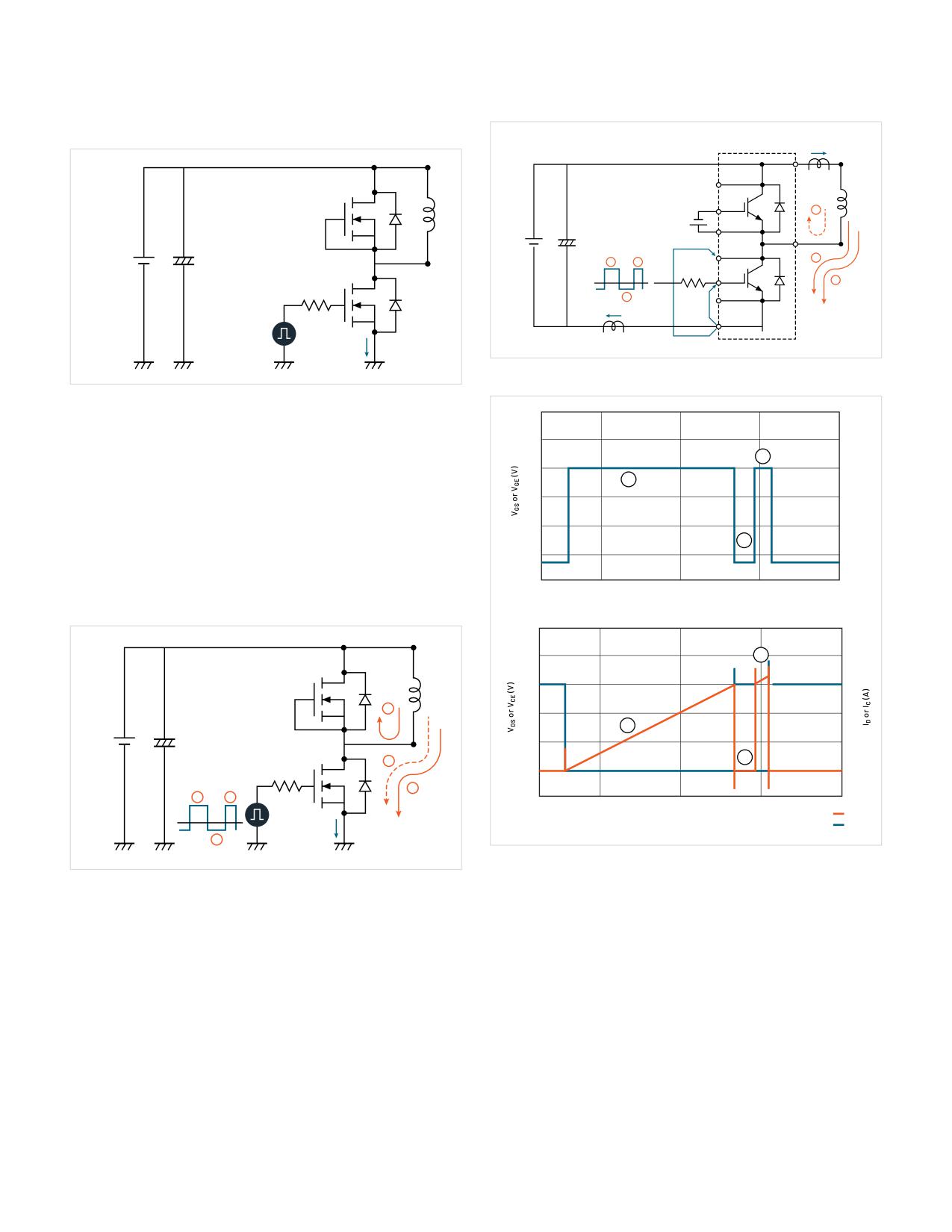
A typical DPT circuit is shown in Figure 4.
iC
Second
DUT
Load
Same type
2
device as
-VGE
+
DUT
VCC
DC
3
Power
1
3
RG
Supply
1
DUT
0 V
2
VCE
VGE
DUT
iE
Arbitrary
Function
Generator
Figure 6: Current Flow using IGBTs as DUTs.
Figure 4: A double pulse test circuit for meausuring swithcing loss on a low-
side FET. The gate of the high-side FET may be driven shorted to prevent it
25
from turning on and a load inductor is connected across it.
20
3
The test is most often performed with an inductive load
15
1
and a power supply, although the exact circuit may vary
10
depending on the intended application of the power devices
under test. [3] The inductor is used to replicate circuit
5
2
conditions in a converter design. The power supply is used
0
to provide voltage to the inductor. An arbitrary/function
-5
generator is used to generate pulses to trigger the gate of
0
10
20
30
40
Time (µsec)
the MOSFET to turn it on and off.
1000
50
800
3
40
600
30
2
400
20
1
VDD
200
10
2
3
0
0
1
1
3
–200
-10
0
10
20
30
40
Time (µsec)
ID or IC
VDS or VCE
2
Figure 7: Double pulse test waveforms .The waveform on top shows the
signal applied to the gate or gate driver. The signals on the bottom are
Figure 5: Current Flow with MOSFETs as DUTs. The Double PulseTest can be
the corresponding drain current (ID) and drain-to-source voltage (VDS).
broken down into three stages, described in the body of this section
Meausurements are taken at the transitions between stages 1 and 2,
and 2 and 3.
Figure 5 shows the current flow within the different stages
of the test for a DPT with MOSFETs. The same current flow
Figure 7 shows typical double pulse test waveforms for a
would apply when testing IGBTs as shown in Figure 6.
low-side MOSFET or IGBT. There are three important stages
of a typical DPT. These stages are represented in Figures 5,
6 and 7 and described here:
4 | WWW.TEK.COM
Double Pulse Testing for Power Semiconductor Devices
APPLICATION NOTE
with an Oscilloscope and Arbitrary Function Generator
1.
Establish the target test current (Id). The width of the
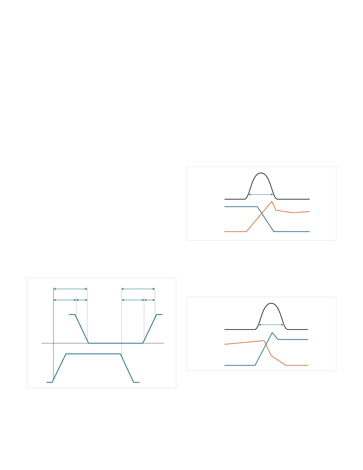
• td(on): Time interval between VGS at 10% of its peak and
first pulse is adjusted to deliver the desired test current
VDS at 90% of its peak amplitude.
through the load inductor.
• tr: Time interval between VDS at 90% and 10% of its peak
2. Turn-off of the first pulse and turn-off measurements.
amplitude. Note that tr is measured when the device
At this point ID has reached the desired test current and
turns on, thus on the falling edge of VDS.
drops to zero as the power device turns off. Turn-off
• td(off): Time interval between VGS at 90% of its peak and
delay (td(off)), fall time (tf), turn-off time (toff), Off Energy
VDS at 10% of its peak amplitude.
(Eoff), dv/dt and di/dt. A load current flows from the load
• tf: Time interval between VDS at 10% and 90% of its peak
inductor through the free-wheeling diode. The turn-
amplitude. Note that tf is measured when the device
off period is kept short to keep the load current to the
turns off, thus on the rising edge of VDS.
target ID.
To calculate energy loss, instantaneous power is calculated
3. Turn-on of the second pulse and turn-on
and then integrated to find energy. Turn-on loss is measured
measurements. This is where turn-on measurements
by integrating power dissipation during turn-on (Figure 9,
are taken as the target ID starts to resume its flow into
Equation 1):
the power device. The current overshoot during this
turn-on is due to temporary excess current during the
reverse recovery of the free-wheeling diode. The second
pulse width is kept just long enough to ensure stable
measurements while avoiding excessive heating.
Eon
Power
Turn-off and Turn-on Measurement
VDS
Definitions
In order to calculate turn-on and turn-off parameters, we
ID
focus on the first turn-off of the switching device and the
subsequent turn-on. At these points ID should be at the
Figure 9. Turn-on energy is calculated by integrating the sampled power
target current level for the test.
waveform during turn-on.
The industry standard definitions for turn-on and turn-off
t
Eon =∫ VDSIDSdt
(1)
timing parameters are illustrated in Figure 8.
0
The same approach is used to calculate energy losses
ton
toff
during the turn-off transition (Figure 10, Equation 2):
td(on)
tr
td(off)
tf
90%
90%
E
off
Power
10%
VDS
10%
0
ID
VGS
90%
DS
V
Figure 10. Turn-off energy is calculated by integrating the sampled power
10%
waveform during turn-off.
0
Figure 8: Switching time standard waveforms [6]. The upper waveform
t
Eoff =∫ VDSIDSdt
(2)
represents VDS and the lower waveform represents VGS. Note that by
0
convention the terms “rising” and “falling” correspond to turn-on (rise) and
turn-off (fall), rather than edges on the VDS waveform.
WWW.TEK.COM | 5
Double Pulse Testing for Power Semiconductor Devices
APPLICATION NOTE
with an Oscilloscope and Arbitrary Function Generator
The math for these calculations can be performed on the
oscilloscope by combining waveform math to multiply
Irr
the VDS and ID waveforms to build a power waveform and
then using an area (integration) measurement to find
L
energy, gated to measure during turn-on and turn-off.
2
The calculations can also be performed on waveform
data by using math software such as MATLAB. In this app
VDD
note, calculations will be performed using measurement
1
algorithms built into the WBG-DPT oscilloscope application.
RG
3
Reverse Recovery Measurements
In addition to turn-on and turn-off losses, it is also
ID
important to understand losses associated with diode
reverse recovery. Reverse recovery current flows through
a diode for a short duration, whenever the diode switches
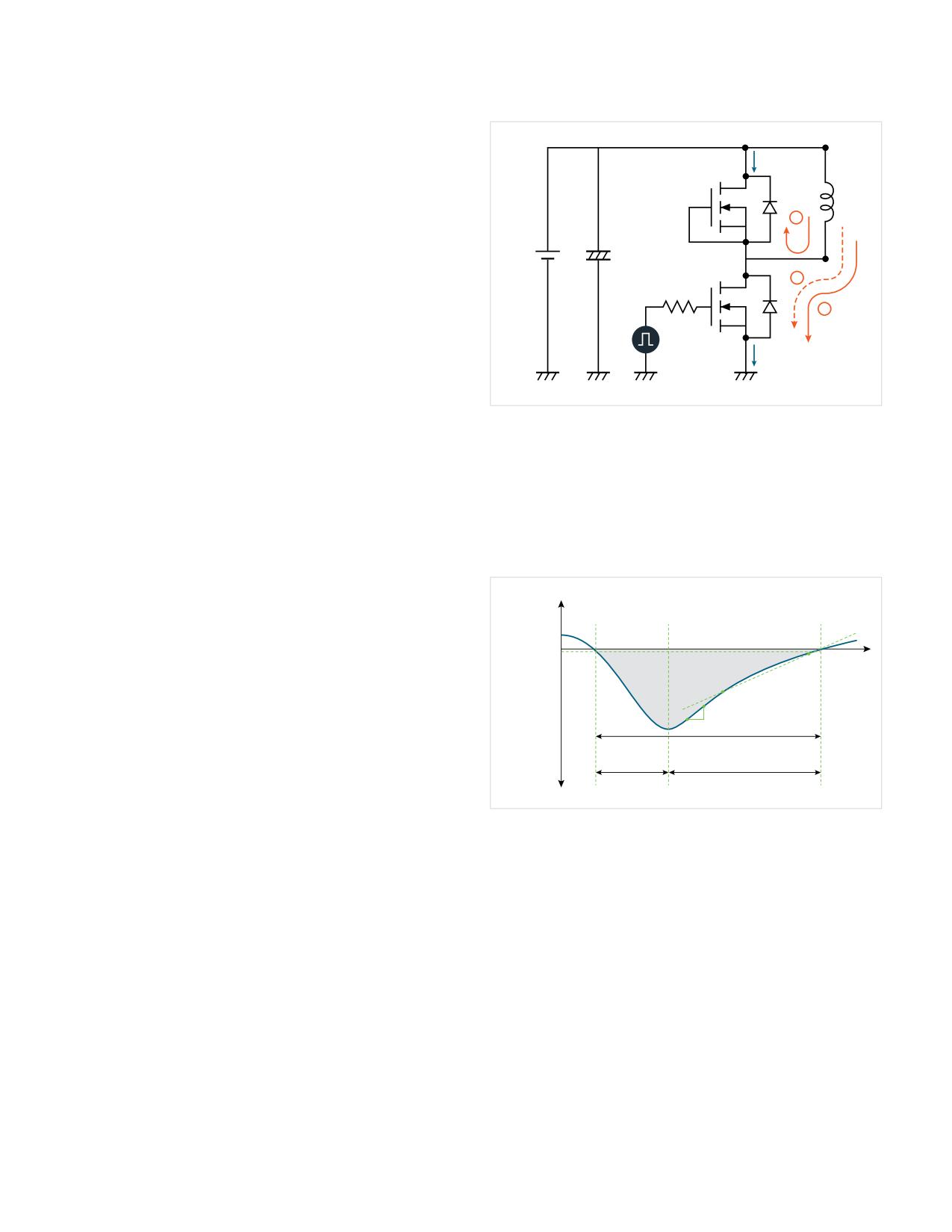
Figure 11: Diode reverse recovery. As the high-side diode switches from
forward bias or “free-wheeling” (Stage 2) to reverse bias (Stage 3), a brief
from forward biased (on) to reverse biased (off).
reverse current flows through the high-side body diode, adding to the low-side
drain current.
The reverse recovery measurement is performed on the
free-wheeling diode in the test setup. In Figure 11, the
Reverse recovery parameters are shown in Figure 12 and
high-side diode is free-wheeling when the low-side diode is
include Trr (reverse recovery time), Irr (reverse recovery
turned off during Stage 2. As the low-side MOSFET turns on
current), Qrr (reverse recovery charge), Err (reverse recovery
again and Stage 3 begins, the high-side diode would ideally
energy), di/dt, and Vsd (forward on voltage).
block reverse current immediately. However, a real diode
conducts briefly before turning off. The reverse recovery
VDS, ID
current translates into energy loss, which impacts the
efficiency of the power converter.
Irr peak
Integration
level
B
Irr (2%)
Qrr
Custom
levels
A
d/dt
trr
ta
tb
Figure 12: Diode reverse recovery measurements are made as the diode is
reverse biased and starts to block current. Reverse recovery measurements
are made between the instant when the diode current passes through zero and
the instant when the extrapolated rising current passes through zero again.
Equation 3 is used to calculate the energy losses during the
transition:
t
Err = ∫ VSDIrr,maxdt
(3)
0
6 | WWW.TEK.COM
Double Pulse Testing for Power Semiconductor Devices
APPLICATION NOTE
with an Oscilloscope and Arbitrary Function Generator
Double Pulse Test Setup
Warning! Since power semiconductor tests can involve
• A DC power supply to deliver sufficient drain voltage
lethal voltages and currents, it is vital that appropriate
(VDD) and drain current (ID) for testing. Examples include
enclosures with safety interlocks and personal protective
the EA-PSI 10000 programmable power supply for
equipment be used!
testing at up to 2 kV and 30 kW, the Keithley 2657A High
Voltage Source Meter Unit (SMU) for testing up to 3 kV,
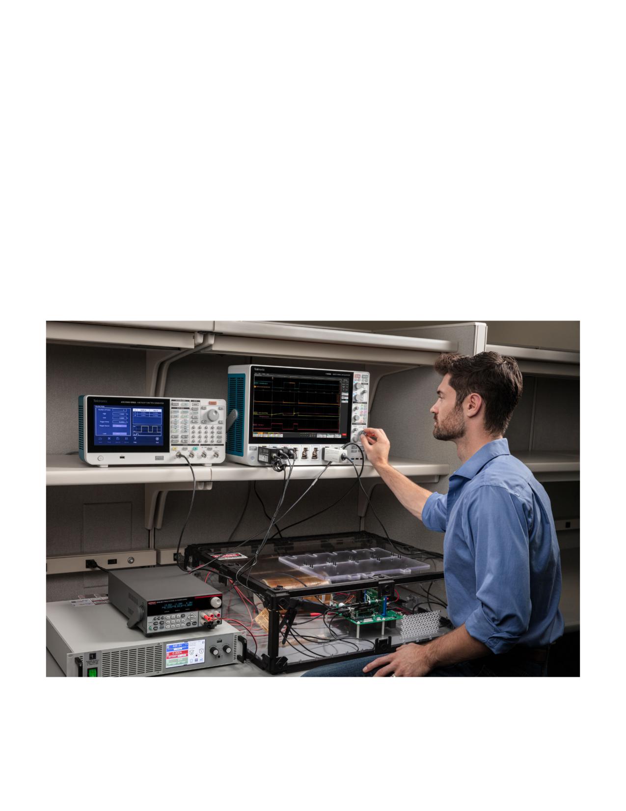
An example of the instrumentation for double pulse testing
or the Keithley 2260B-800-2, programmable DC power
is shown in Figure 13. The general setup includes:
supply for testing up to 800 V.
• A signal source to provide gate drive signals, usually
• A DC power supply for any supporting electronics such
through an isolated gate driver. The widths of each
as gate drive ICs. Examples include the Keithley Series
pulse must be independently variable. Because of this
2230 or Series 2280S DC power supply.
an arbitrary/function generator (AFG) is commonly used
• A multi-channel digital oscilloscope to acquire
and special DPT software is valuable for setting up the
and measure VDS, VGS, and ID. This application note
stimulus. The AFG may be a standalone instrument such
describes testing with a Tektronix 5 Series B MSO, but
as the AFG31000 Series or built into the oscilloscope
a 4 Series B MSO and 6 Series B MSO operate the same
such as those available on 4, 5 and 6 Series MSOs.
albeit with different specifications.
Figure 13: Double pulse test setup for testing a SiC low-side FET, including an MSO58B oscillscope with Double Pulse Testing Application Software, AFG31252
arbitrary/function generator, PSB 11500-06 1.5 kW DC power supply for VDD, and Keithley 2231A-30-3 triple channel power supply to power gate drivers. A TICP0100
isolated current probe is connected across a shunt resistance to measure drain current. A TCP0030A clamp-on current probe is used to measure the inductor
current. In this setup the source of the low-side FET is grounded allowing the use of earth-referenced probes. A TPP0850 high-voltage passive probe is connected
to VDS and a TPP1000 passive probe with MMCX cartridge is connected to VGS.
WWW.TEK.COM | 7
Double Pulse Testing for Power Semiconductor Devices
APPLICATION NOTE
with an Oscilloscope and Arbitrary Function Generator
• The oscilloscope must be equipped with appropriate
This application note covers the math behind the
probes. Probe selection is critical for getting valid
measurements, but the automated DPT tools will be used in
results and will be covered in the next section.
the measurement examples.
• Double pulse testing application software on
Especially when compared to manual test methods or
the oscilloscope facilitates making repeatable
custom code, the on-scope software provides:
measurements. This application note describes testing
• Repeatable measurements, even on signals with ringing
using Double Pulse Test Software Opt. WBG- DPT for 4,
5 and 6 Series B MSOs.
• Measurements per JEDEC and IEC standards or using
custom parameters
Double Pulse Test Software on the 4/5/6
• Ability to generate double pulse gate drive signal from
Series MSO
an AFG31000 Series Arbitrary/Function Generator
The measurements associated with double pulse testing
• A preset feature to facilitate oscilloscope setup
can be performed using the built-in capabilities of the 4, 5
and 6 Series MSO oscilloscopes, since these oscilloscopes
• A unique deskew capability that can be performed post-
include the multiplication, differentiation and integration
acquisition, without special fixtures
functions as well as adjustable gating and reference
• Easy navigation between pulses and annotation
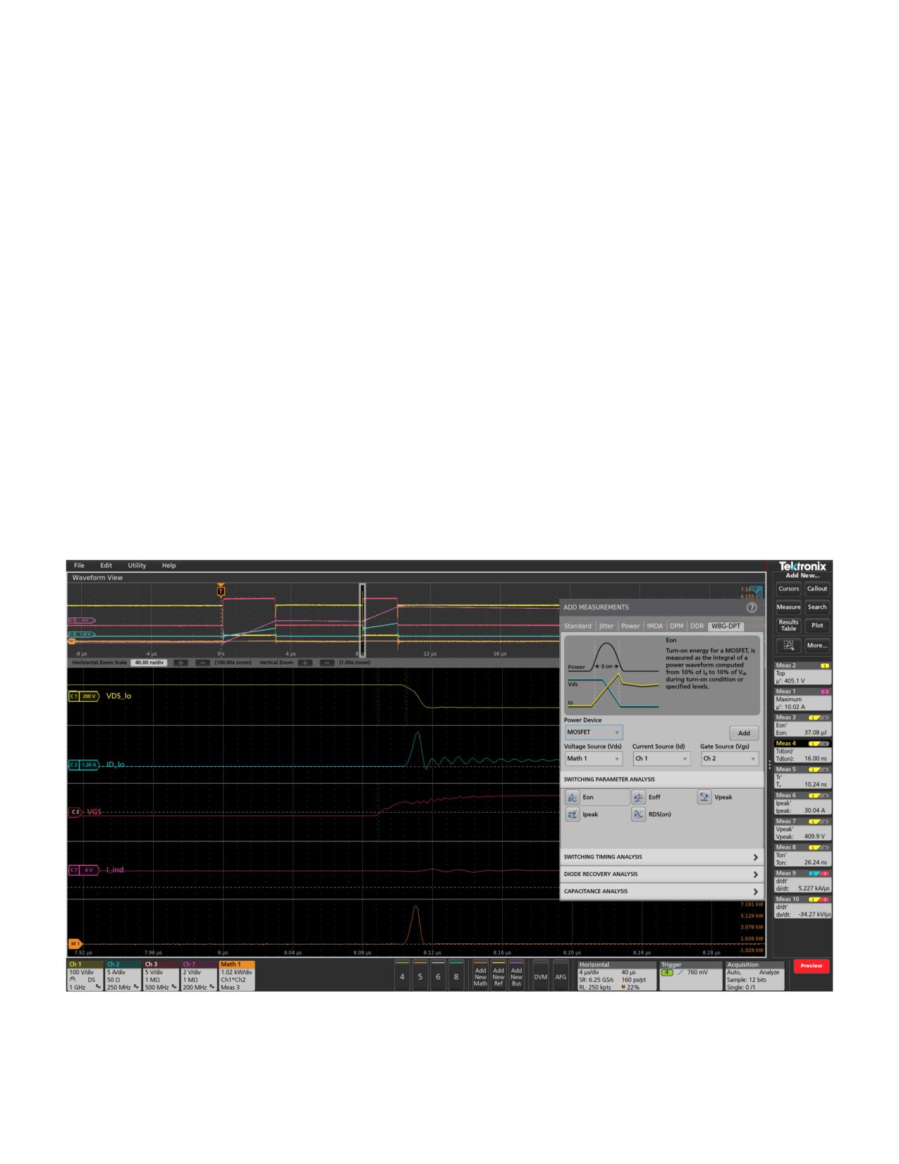
levels. However, the Wide Bandgap Double Pulse Test
• Summarized measurements in results tables
(WBG-DPT) application (Figure 14) which is available for
these instruments automates double pulse measurements
• Pass/Fail testing with configurable limits and actions to
without the need for any custom programming. Automated
be taken on failures
measurements can offer greater repeatability and faster
• Reports, session files and waveforms to help
results compared to manual setups and measurements.
document results
Figure 14. On-scope double-pulse testing software such as the WBG-DPT Wide Bandgap Double Pulse Testing application automatess setup and helps to achieve
consistent results.
8 | WWW.TEK.COM
Double Pulse Testing for Power Semiconductor Devices
APPLICATION NOTE
with an Oscilloscope and Arbitrary Function Generator
• Full programmatic interface for test automation
In addition to switching loss, timing and reverse recovery,
the WBG-DPT application also supports automated:
• Deadtime measurements
• Dynamic RDS(on) measurements, without
external clamping
These parameters can be measured using a setup similar to
double pulse testing, but different probes and connections
will be required.
For more information about the WBG-DPT app, please
refer to the Option 4-WBG-DPT, 5-WBG-DPT, 6-WBG-DPT
Application Datasheet.
Gate Drive Signal Source
DPT requires a gate drive signal source capable of providing
multiple pulses with independently adjustable widths.
Pulses may be generated by using a microcontroller board
with custom software, but off-the-shelf signal generators
can generally provide predictable performance and finer
control of pulse parameters. Arbitrary/function generators
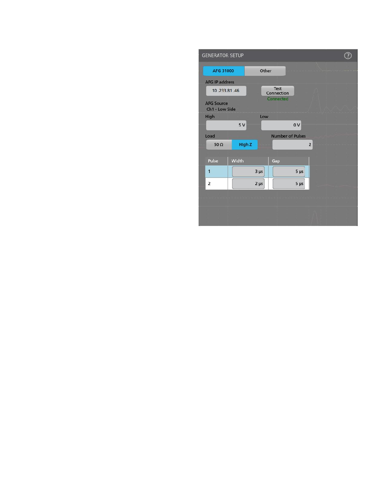
Figure 15. In addition to front panel control on the AFG31000, the generator
(AFGs) are a cost-effective category of signal sources for
can be controlled from the DPT application on the oscilloscope using a LAN
connection.
this application. This can be a standalone generator or can
be built into the oscilloscope. For example:
•
4, 5 and 6 Series MSO oscilloscopes offer an optional
built-in AFG. This AFG has many of the same capabilities
• AFG31000 Series Arbitrary/Function Generators
of a standalone generator, but is tightly integrated into
offer a Double Pulse Test Application on the unit to
the oscilloscope, sharing the same user interface. The
quickly generate pulses with varying pulse widths. The
built-in AFG cannot be controlled by the DPT application
next section gives a description of this feature. The
software, but may be controlled with custom software
AFG31000 Series is available with dual outputs and
running on Windows on the 5 or 6 Series MSO (see
can serve as general-purpose function generators,
Double Pulse Testing Power Semiconductor Devices
independent of an oscilloscope. In this application
with a 5 or 6 Series MSO with Built-in Arbitrary Function
note the AFG 31000 is controlled from its front panel,
Generator).
however the AFG31000 can also be connected via LAN
and controlled from within the WBG-DPT Double Pulse
Testing application software on the 4, 5 or 6 Series
MSOs. The configuration menu for contolling a LAN-
connected AFG is shown in Figure 15.
WWW.TEK.COM | 9
Double Pulse Testing for Power Semiconductor Devices
APPLICATION NOTE
with an Oscilloscope and Arbitrary Function Generator
Generating Double Pulse Gate Signals on
the AFG31000
The AFG31000 Double Pulse Test Application can be
downloaded directly from the tek.com website and installed
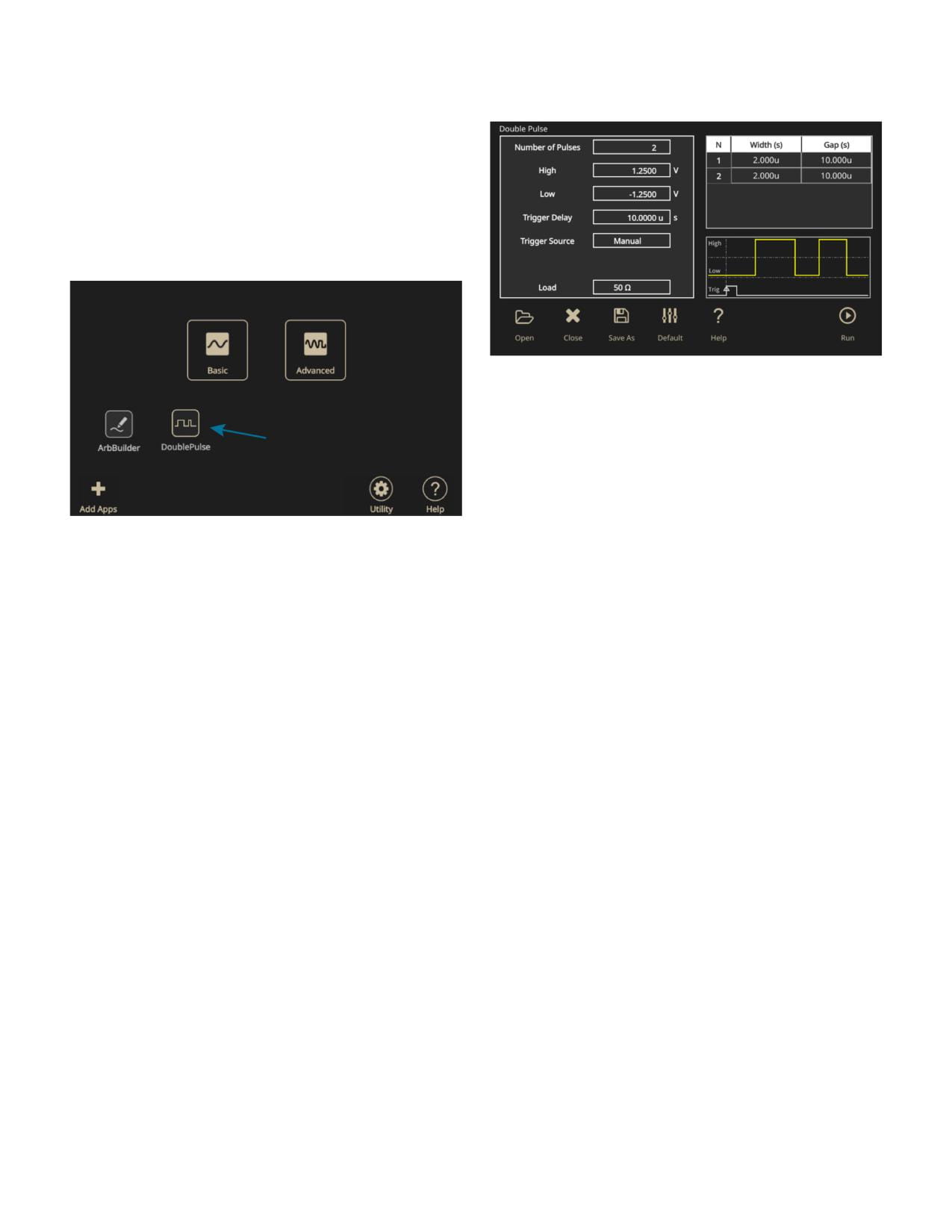
onto the AFG31000. Figure 16 shows the Double Pulse
Test icon on the home screen of the AFG31000 after the
application is downloaded and installed on the unit.
Figure 17: Double Pulse Test Application on the AFG31000 enables easy
configuration of multiple pulses with different widths.
Oscilloscope Probing for Double Pulse
Testing
The reliability of double pulse measurements depends
on the choice of appropriate voltage and current probes,
as well as adherence to best practices. A comprehensive
Figure 16: AFG31000 Home Screen with the Double Pulse Testing Application
installed.
discussion of probing is outside the scope of this
application note, but some high-level considerations for
The Double Pulse Test Application lets the user create
probing in double pulse tests are included here.
multiple pulses with varying pulse widths from the front
First and foremost, probes and accessories must always
panel of the generator. The application is intuitive and
have sufficient ratings to handle the maximum voltage or
quick to set up. The first pulse width is adjusted to get the
current expected in testing. This is especially true in power
desired switching current value. The second pulse width
converter measurements since current and voltage levels
can be adjusted independently and is usually shorter to
tend to be higher than general electronics applications.
limit heating in the DUT. The time between the pulses is also
Also, extra thought and planning must be dedicated
configurable.
to grounding, insulation and isolation to avoid damage
Figure 17 shows the Double Pulse Test application window.
or injury.
Here the user can set the:
Voltage Probes
• Number of pulses: 2 to 30 pulses
Single-ended, passive voltage probes are simpler and less
• High and low voltage magnitude (V)
expensive than differential probes, but their application in
• Trigger delay (s)
power converters is limited. This is because their reference
• Trigger source - manual, external, or timer
leads are tied to earth ground through the oscilloscope.
When using passive probes keep ground leads short and
• Load - 50 Ω or high Z
shield connections if possible. MMCX connectors, for
example, offer high bandwidth and shielding.
Differential voltage probes are more versatile in power
applications, since they are not directly connected to
earth ground. They are designed for making floating
measurements. Differential probes with appropriate
voltage ratings are commonly used for measuring drain-to-
source voltages.
10 | WWW.TEK.COM

Double Pulse Testing for Power Semiconductor Devices
APPLICATION NOTE
with an Oscilloscope and Arbitrary Function Generator
Note that traditional differential probes face limitations in
inherent in coil-based designs will impact the circuit under
common mode rejection. This can impact high-side gate
test, especially those with fast rise-time signals that occur
measurements (VGS) in which a relatively small voltage
in SiC and GaN FETs.
is “riding on” a high common mode signal. When making
Rogowski current clamps are convenient for their flexibility
high-side VGS measurements, an isolated voltage probe is
and wide current ranges. However, they are not able to
recommended as they greatly reduce common mode noise
measure DC and bandwidth limitations in tens of megahertz
in measurements.
make them of limited use in DPT.
Current Probes
To achieve the high bandwidth and low insertion inductance
Clamp-on AC/DC oscilloscope current probes incorporate
required for double pulse testing wide bandgap devices,
Hall effect sensors as well as coils, and are often used
designers often turn to shunt resistors or current viewing
for measuring power converter circuits. Passive current
resistors (CVRs). Unlike general-purpose differential
transformers (CTs) may also be used for measurements
probes, shunt probes such as the Tektronix TICP IsoVu™
but cannot measure DC. High-quality AC/DC probes and
Isolated Current Probe are special voltage probes designed
AC-only CTs roll off at around 100 MHz, and it is important to
specifically to measure low-level signals across shunt
note their insertion inductance. This inductance, which is
resistors.
Table 1. A survey of current measurement methods used to measure drain current in DPT test circuits for testing wide bandgap devices.
Model
Type
Side
Max Current
Bandwidth
Rise-time
Notes
Clamp-on
50A (peak)
• Due to limited bandwidth, it may not be the
TCP0030A
LS, HS
120 MHz
<2.92 ns
AC/DC
30 A (rms)
best option for WBG devices.
• They are the most popular choice for
Coaxial Shunt
CVR
LS, HS
100+ Amps
2000 MHz
0.18 ns
current measurement for WBG devices dur
to their higher bandwidth and accuracy.
100 A (peak)
Current Monitor
CT
LS
200 MHz
2 ns
• Provide galvanic isolation.
2.5 A (rms)
• Introduces additional parasitic inductance
5 kA (peak)
in the power loop.
Current Monitor
CT
LS
20 MHz
20 ns
50 A (rms)
Current
10 kA (peak)
• Due to limited bandwidth and accuracy,
CT
LS
50 MHz
7 ns
Transformer
35 A (rms)
the Rogowski coil is not suitable for
WBG devices.
CWT
Rogowski Coil
LS
300 A (peak)
15 MHz
25 ns
• Add insertion inductance to the loop.
WWW.TEK.COM | 11
Double Pulse Testing for Power Semiconductor Devices
APPLICATION NOTE
with an Oscilloscope and Arbitrary Function Generator
Probe Connections
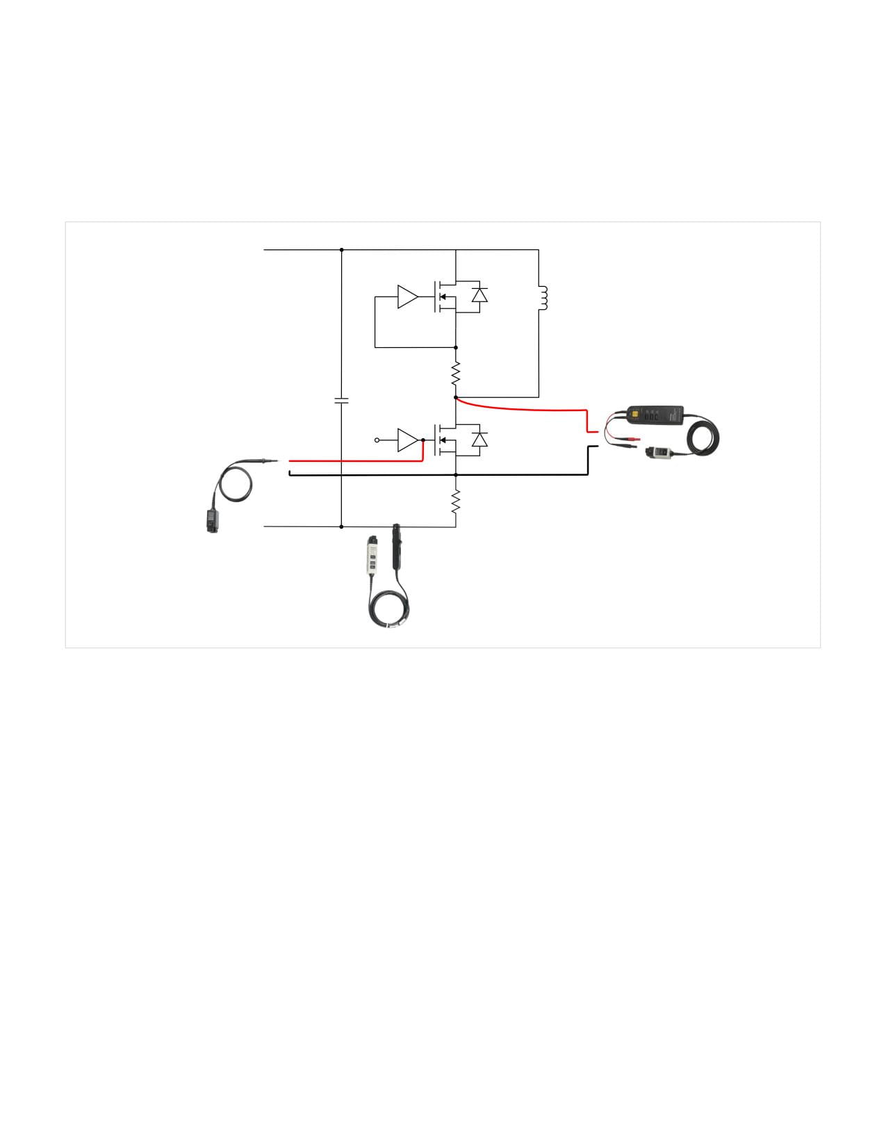
This section covers probe recommendations and connections for switching measurements. A common DPT approach is
to measure switching loss on the low-side switch. Although some designers carefully drive both the high and low switches
during testing, it is a common simplification to force the high-side switch off by shorting the gate to source. This is shown in
Figure 18.
VDD
Gate
Drive
Air Core
Inductor
CVR
Gate
Drive
Passive Voltage Probe
(Earth Referenced)
High Differential
Voltage Probe
CVR
AC/DC
Current Probe
Figure 18. Probe connections for low-side switching measurements. Current may also be measured as the voltage drop across the CVR if one is available.
For low-side device switching testing shown in Figure 18, these probes represent a good starting configuration for most
applications.
• VGS-Lo - TPP Series 10X passive probes offer an effective solution and are included with 4, 5 and 6 Series MSOs. In this
case the source of the FET will be grounded through the oscilloscope. Installing an MMCX connector across the gate
makes a high-bandwidth test point and optional MMCX cartridges are available for TPP1000 probes.
• VDS-Lo - High voltage passive probes are a good solution if the low-side source node can be grounded. The TPP0850 is a
50X attenuating probe rated for 1000 VRMS CAT II applications. If the source node must not be grounded, a THDP/TMDP
Series differential voltage probe is recommended.
• ID-Lo - TCP Series current probe. If insertion inductance is a concern and bandwidth higher than 120 MHz is needed, then
a TICP Series IsoVu Isolated Current Probe is recommended along with a high-performance shunt resistor or CVR.
12 | WWW.TEK.COM
Double Pulse Testing for Power Semiconductor Devices
APPLICATION NOTE
with an Oscilloscope and Arbitrary Function Generator
VDD
High Differential
Gate
Voltage Probe
Drive
Isolated
Voltage Probe
CVR
Isolated Current
Shunt Probe
Gate
Drive
Air Core
Inductor
CVR
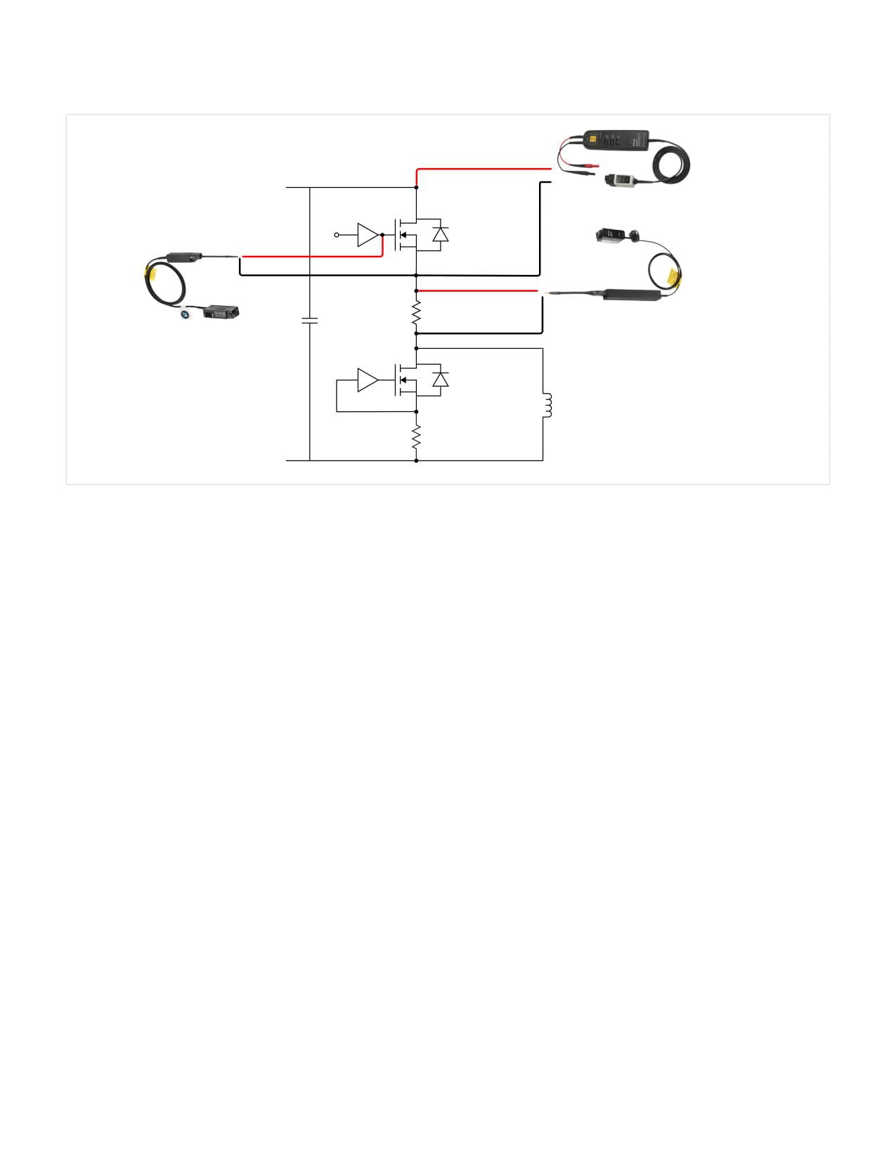
Figure 19. Probe connections for high-side switching measurements.
For testing switching loss on a high-side FET, as shown in Figure 19, the low-side FET is forced off, and the high-side FET is
driven. These probes represent a good starting point for making measurements:
• VGS-Hi - TIVP IsoVu Isolated Voltage Probe
• VDS-Hi - THDP/TMDP Series differential voltage probe
• ID-Hi - TICP Series IsoVu Isolated Current Probe is recommended along with a high-performance shunt resistor or CVR.
WWW.TEK.COM | 13
Double Pulse Testing for Power Semiconductor Devices
APPLICATION NOTE
with an Oscilloscope and Arbitrary Function Generator
VDD
Gate
Drive
Isolated
Voltage Probe
CVR
Gate
Drive
High Differential
Voltage Probe
Air Core
Inductor
CVR
Isolated Current
Shunt Probe
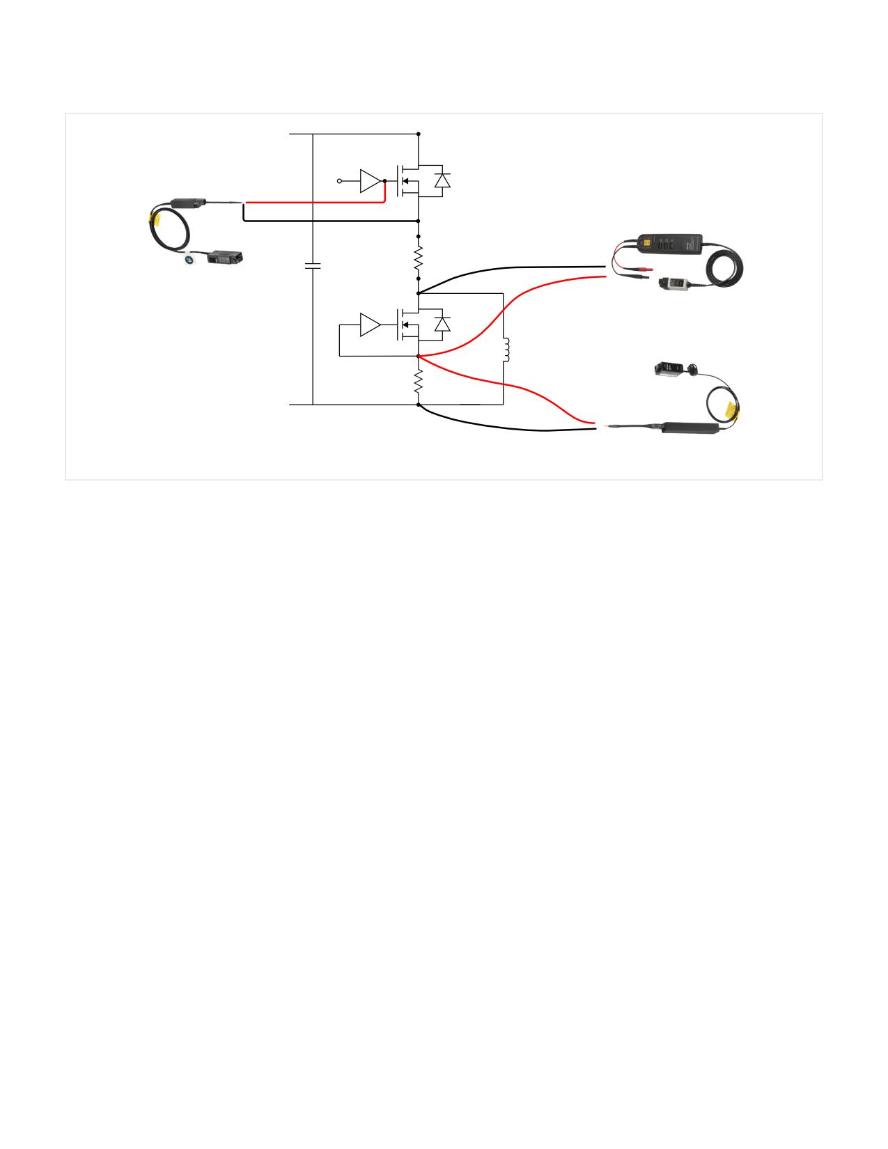
Figure 20. Probe configuration for measuring reveres recovery parameters on a low-side diode. In this setup the load inductor is on the low side and the high-side
FET is being driven.
An example probe configuration for testing reverse recovery of a low-side diode is shown in Figure 20. The probes in this
example are:
• VGS-Hi - TIVP IsoVu Isolated Voltage Probe
• VSD-Lo - THDP/TMDP Series differential voltage probe. In Figure 20 the probe is connected across the body diode in the
forward direction.
• ID-Lo - TICP Series IsoVu Isolated Current Probe is recommended along with a high-performance shunt resistor or CVR.
A clamp on current probe such as a TCP Series may also be used if access is available.
14 | WWW.TEK.COM
Double Pulse Testing for Power Semiconductor Devices
APPLICATION NOTE
with an Oscilloscope and Arbitrary Function Generator
• Keithley 2231A-30-3 triple-output DC power supply (3 A
Double Pulse Test
at 30 V max) to power gate drivers and other low-voltage
Measurement Example
electronics
In this section actual measurements will be configured,
• Tektronix 5 Series B MSO oscilloscope (4 or 6 Series B
taken and explained. Using an example setup, switching
MSOs may also be used) with WBG-DPT Double Pulse
loss and timing will be measured on the low-side switch, and
Testing application software and the following probes:
the test circuit with be reconfigured to measure reverse
- TPP1000 300 V, 1 GHz ground-referenced probe for
recovery loss on the low-side diode. Testing of the SiC FETs
low-side VGS
will be performed at 400 VDC.
- TIVP1 2.5 kV, 1 GHz IsoVu isolated voltage probe for
high-side VGS
The Example Test Setup
- TPP0850 1000 V, 800 MHz high voltage ground-
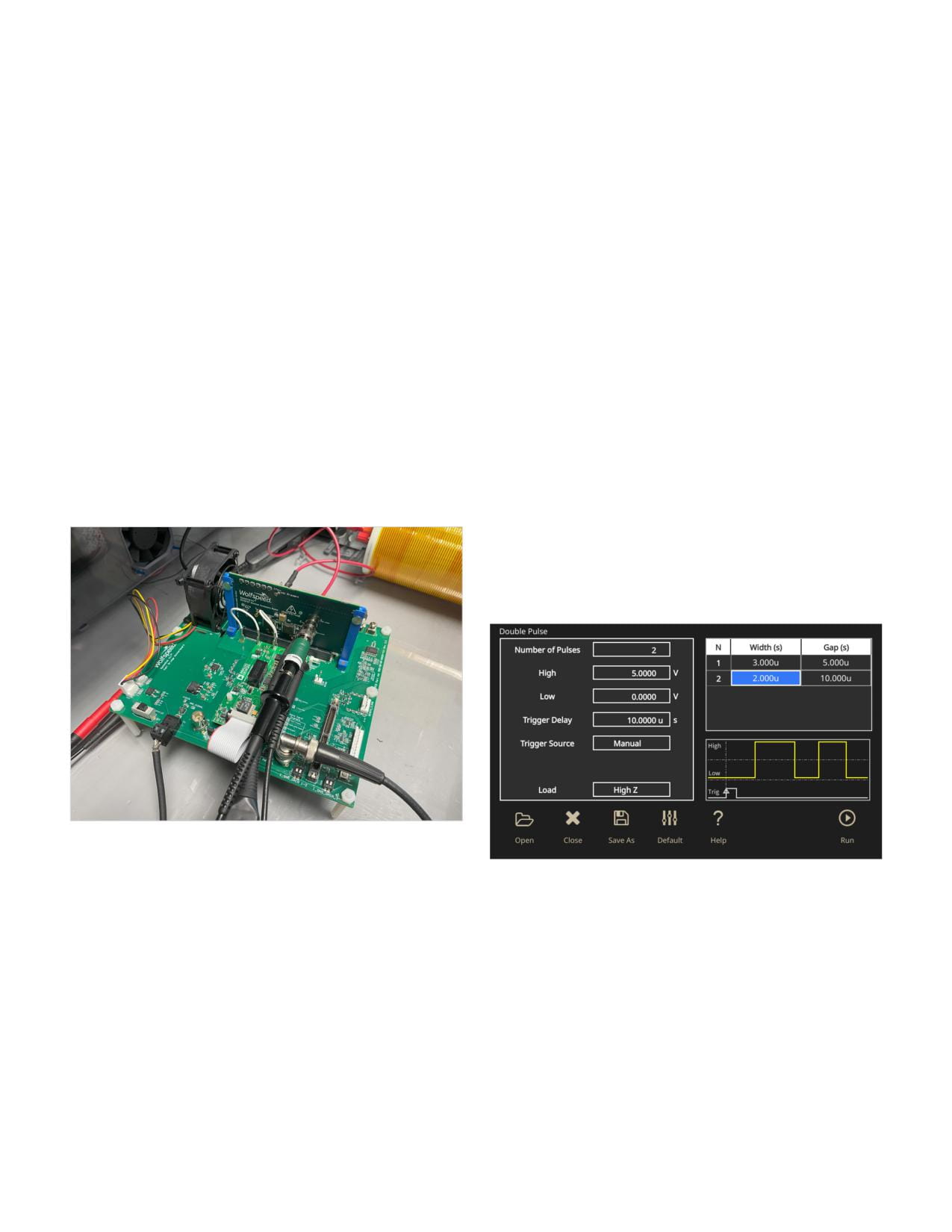
For this case study, measurements are taken on a
referenced probe for low-side VDS measurements
Wolfspeed SpeedVal Kit™ Half-Bridge Motherboard with
SpeedVal Kit TOLL Power Daughter Card [13]. The daughter
- TMDP0200 750 V, 200 MHz high voltage differential
card includes two 650 V SiC MOSFETs in a half-bridge
probe for high-side VDS measurements
configuration. The setup uses 1 mH air core load, and the
- TICP0100 1 GHz IsoVu isolated current probe for
source of the low-side FET is tied to earth ground through a
measuring drain current via shunts
shunt resistor. The test setup is shown, configured for low-
- TCP0030A 30 A, 120 MHz clamp-on current probe for
side switching measurements, in Figure 21.
load inductor current
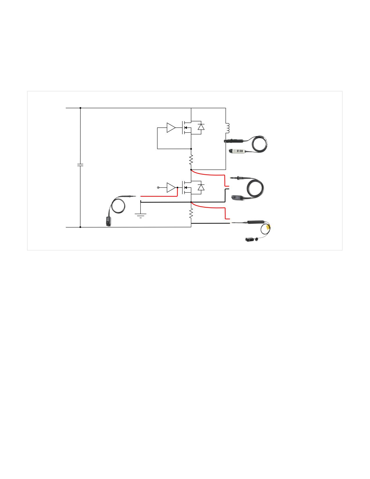
Configuring the Gate Drive Signal
The double pulse stimulus was set on the AFG31000 as
shown in the screen capture in Figure 22.
Figure 21: Wolfspeeed SpeedVal Kit with oscilloscope probes, power
connections and load inductor configured for double pulse testing the
low-side FET.
Figure 22: Doublepulse test settings on the AFG31000.
Instrumentation used in the examples includes:
The amplitude of the pulses was set to 5 V into high
• Tektronix AFG31252 arbitrary/function generator with
impedance. The pulse width for the first pulse was set to
Double Pulse Testing Application
3 µs, the gap was set to 5 µs and the second pulse was set to
2 µs. The trigger was set to manual.
• Elektro-Automatik PSB 11500-06 1.5 kW DC power
supply to provide VDD
WWW.TEK.COM | 15
Double Pulse Testing for Power Semiconductor Devices
APPLICATION NOTE
with an Oscilloscope and Arbitrary Function Generator
Probe Configuration for Low-Side Switching Measurements
Before making any connections, always double-check to make sure circuits are de-energized!
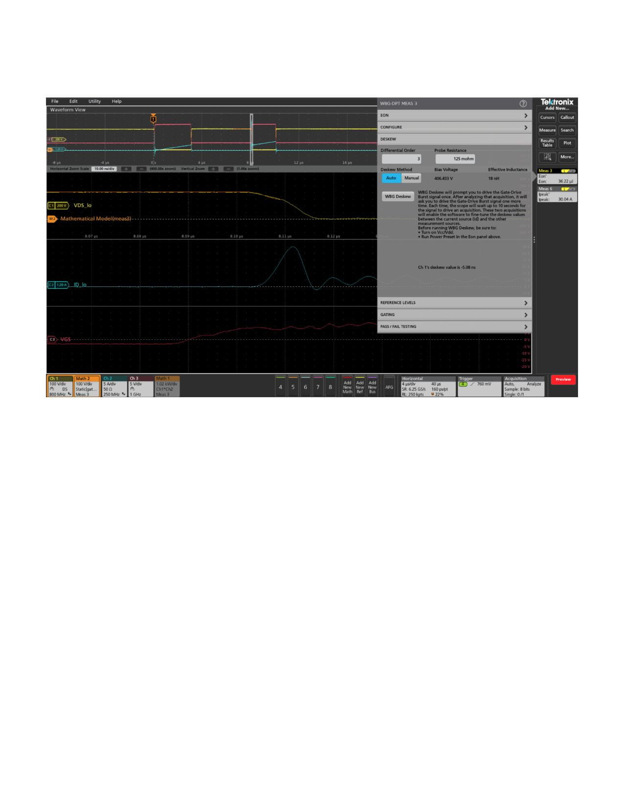
The first measurements taken were low-side switching measurements. For these measurements, the oscilloscope probes
were connected as shown in Figure 23. In addition, the signal from the AFG was routed into Channel 4 for triggering.
VDD
Gate
Drive
I_ind: Channel 7
Air Core
TCP0030A AC/DC
Inductor
Current Probe
CVR
VDS_lo: Channel 1
TPP0850 Voltage Probe
Gate
(Earth Referenced)
VGS: Channel 3
Drive
TPP1000 Voltage Probe
(Earth Referenced)
ID_lo: Channel 2
CVR
TICP Isolated Current Probe
Figure 23. Probe connections for low-side switching parameter measurements.
Deskewing Voltage and Current Signals
For accurate power measurements, it is critical to correct
However, in the WBG-DPT application software, the skew
for the different delays in current and voltage probes,
of the measurement system is performed as a post-
especially between VDS and ID. Any delays between the
acquisition operation and does not require any special
probes will introduce error in any power and energy
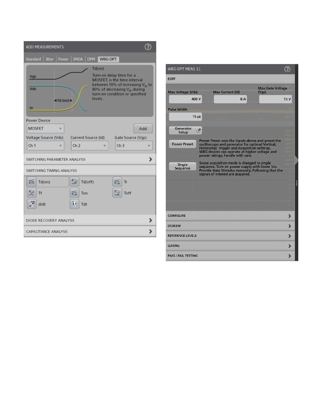
fixtures or signal sources [12]. The WBG Deskew function
measurements. In a traditional test procedure, one must
built into the WBG-DPT application software (Figure 24)
perform deskew of the voltage and current probes before
calculates and corrects for the skew between VDS and ID or
connecting to the DUT. However, this approach can be
VCE and IC when the power device is a MOSFET or an IGBT
difficult in high-power setups, since this approach requires
respectively. The skew value is then applied to the VDS or VCE
the use of special fixtures and/or replacing the load inductor
signal to align it with the drain or emitter current.
with a resistive load.
16 | WWW.TEK.COM
Double Pulse Testing for Power Semiconductor Devices
APPLICATION NOTE
with an Oscilloscope and Arbitrary Function Generator
For the measurements that follow, the probes were deskewed by following this procedure.
Figure 24. Using the WBG-DPT application, deskew can be performed using measured waveforms in a double-pulse test setup. The user specifies the value of the
shunt resistance (125 mΩ in this case). Clicking the WBG Deskew button automatically calculates a skew correction and aligns the VDS and ID waveforms.
Measuring Low-Side Switching Timing and
Making Switching Loss Measurements with the
Energy Losses
WBG-DPT Application
Switching timing measurements can be made using
As with all measurements on the 4, 5 and 6 Series MSOs,
cursors, but care must be taken to position the cursors
the WBG-DPT application controls are accessed through
precisely and assign them to the correct channels, since
the Measure button in the upper right corner of the
industry standard measurements are made between
touchscreen. For this example, the Power Device type was
edges on VGS and VDS (see Figure 8.) In this example,
set to MOSFET. The VDS, ID, and VGS sources were set to
measurements will be defined by the WBG-DPT application
Channels 1, 2 and 3 as shown in Figure 25.
on the oscilloscope to facilitate the assignment of channels
and setting reference levels.
Similarly, energy losses during switching can be
determined using channel math to multiply voltage and
current to generate a power waveform, and using an area
measurement (integration) to determine energy. To simplify
this, the WBG-DPT app provides Eon and Eoff measurements
under the Switching Parameter Analysis group. This
measurement performs the necessary math and quickly
displays the result.
WWW.TEK.COM | 17
Double Pulse Testing for Power Semiconductor Devices
APPLICATION NOTE
with an Oscilloscope and Arbitrary Function Generator
Each measurement can be individually configured as shown
in the example for the turn-off energy measurement (Eoff)
shown Figures 26 and 27.
Figure 25. The Switching Timing Analysis measurements in the WBG-
DPTapplication.
Measuring Turn-off Parameters
Figure 26. Example measurement setup for Eoff. The maximum and pulse
width values are used by the Power Preset function to automatically configure
To measure turn-off characteristics several measurements
vertical and horizontal scales, respectively.
were selected:
• “Top” amplitude measurement on VDS for monitoring
• Maximum current through the inductor for monitoring
• Turn off delay, Td(off)
• Fall time, Tf
• Peak VDS, Vpeak
• Turn-off time, Toff
• Current slew rate, d/dt
• Voltage slew rate, d/dt
• Output charge, Qoss
18 | WWW.TEK.COM
Double Pulse Testing for Power Semiconductor Devices
APPLICATION NOTE
with an Oscilloscope and Arbitrary Function Generator
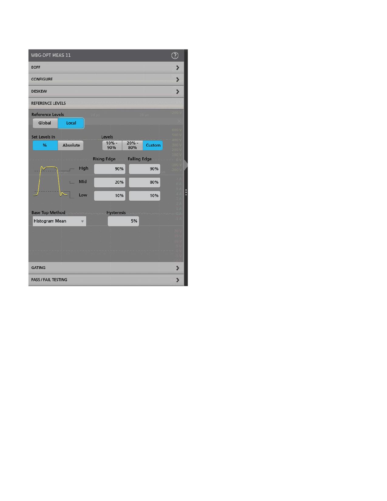
The WBG-DPT application software defaults to the industry
standard 10% and 90% threshold values shown in Figure 27.
It also supports custom threshold settings. The default
levels are used in this example.
After double-checking connections and power supply
settings, and sealing the safety enclosure, power-up of the
system was started.
• First, power was applied to the gate drive electronics by
activating the lower-voltage power supply.
• Power was applied to VDD by activating the high-voltage
power supply. At this point the circuit high voltage
was present!
• The oscilloscope was armed for an acquisition.
• The AFG31000 was triggered to generate the gate
drive pulses.
• The high-voltage supply for VDD was turned off
• The low-voltage supply for gate drivers was put
in standby
Figure 27: The DPT software on the oscilloscope supports both standard and
custom reference levels. Levels can be applied to all measurement (Global)
or to individual measurement (Local). A hysteresis band sets a range on the
reference level through which the signal must pass to be recognized as a
transition. This helps to filter out spurious events.
WWW.TEK.COM | 19
Double Pulse Testing for Power Semiconductor Devices
APPLICATION NOTE
with an Oscilloscope and Arbitrary Function Generator
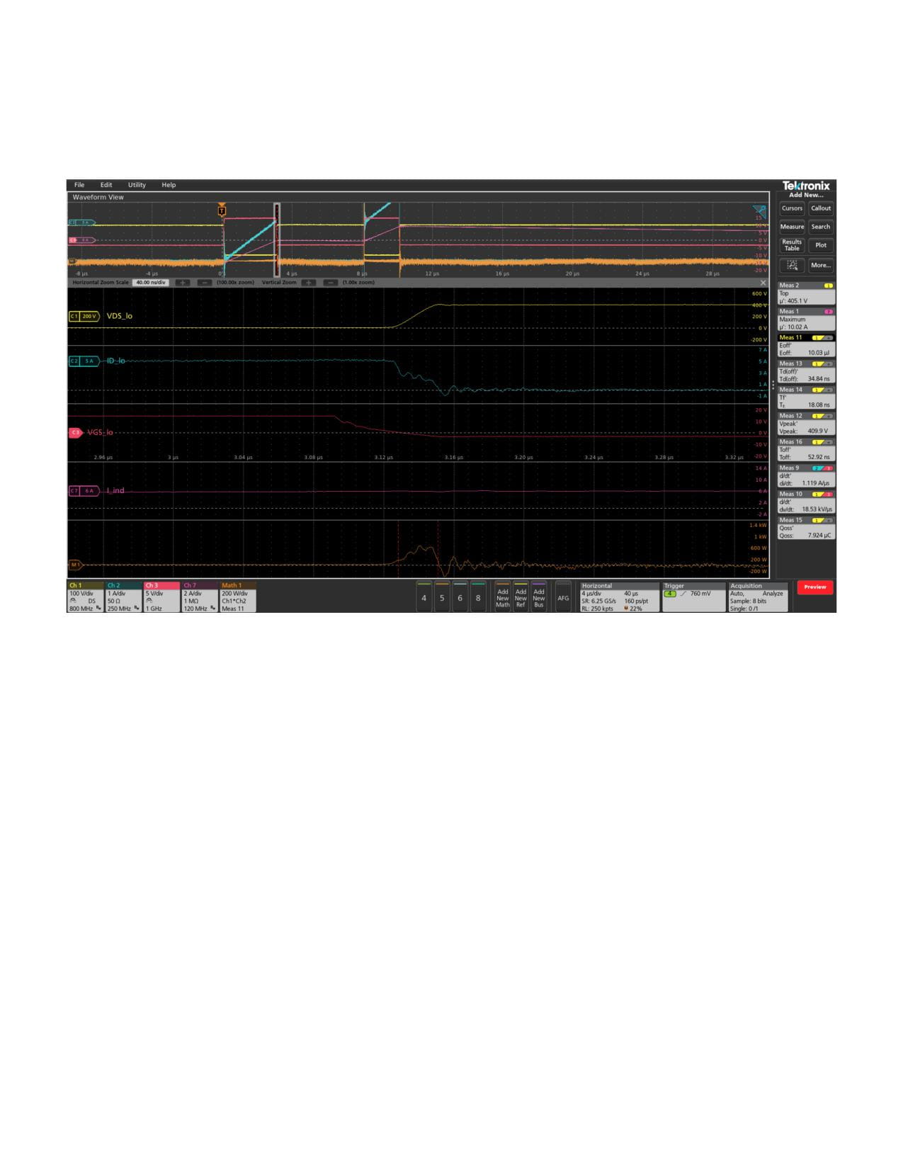
The resulting waveforms were captured and measurements were displayed on the oscilloscope. Data and settings were
stored as a “session” to document the measurements. The screen capture in Figure 28 shows the detail of the turn-off event
at the end of the first VGS pulse, after ID has risen to the target value.
Figure 28: Turn-off parameters and waveforms.
20 | WWW.TEK.COM
Double Pulse Testing for Power Semiconductor Devices
APPLICATION NOTE
with an Oscilloscope and Arbitrary Function Generator
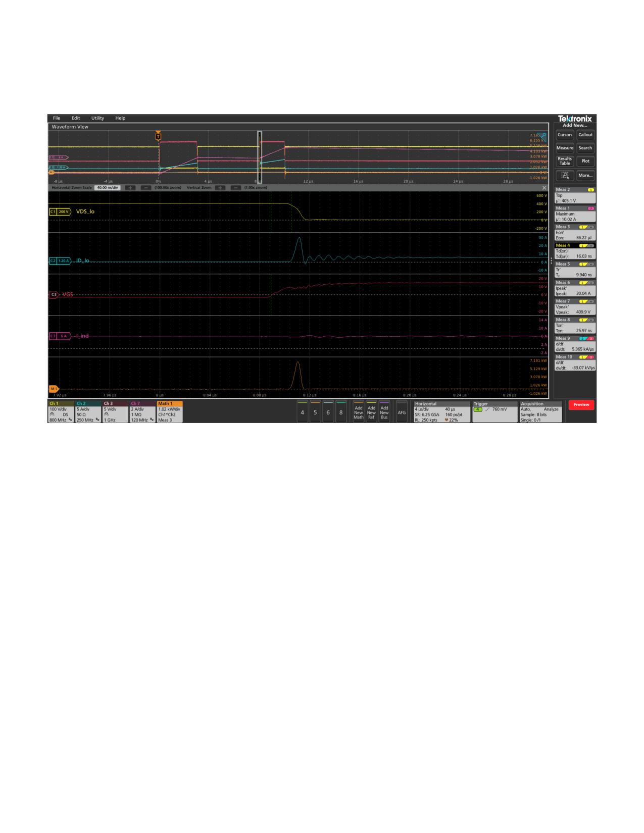
A second set of measurements were configured to document turn-on. Figure 29 shows the detail of the turn-on event at the
beginning of the second VGS pulse.
Figure 29: Turn-on parameters and waveforms.
Measuring Reverse Recovery
The reverse recovery characteristics of the free-wheeling
The following measurements, found in the WBG-DPT
diodes can be measured on the low-side or high-side
application in the Diode Reverse Recovery group, were set
devices. For this example, the diode on the low-side was
up for this test:
measured, since the device under test provides easy access
• Peak VDS
to a shunt on the low-side source, through a shielded,
high-bandwidth MMCX connector. To measure the low-side
• Maximum inductor current
diode, the load inductor must be placed across the low-side
• Reverse recovery time, Trr
switch, and the high-side FET is pulsed. The low-side diode
• Minimum reverse recovery current, Irrm
behaves as s free-wheeling diode, conducting inductor
current when the high-side FET is turned off. Reverse
• Reverse recovery charge, Qrr
recovery current will flow briefly when the high-side FET
• Reverse recovery energy, Err
turns back on, and the low-side diode is reverse-biased.
WWW.TEK.COM | 21
Double Pulse Testing for Power Semiconductor Devices
APPLICATION NOTE
with an Oscilloscope and Arbitrary Function Generator
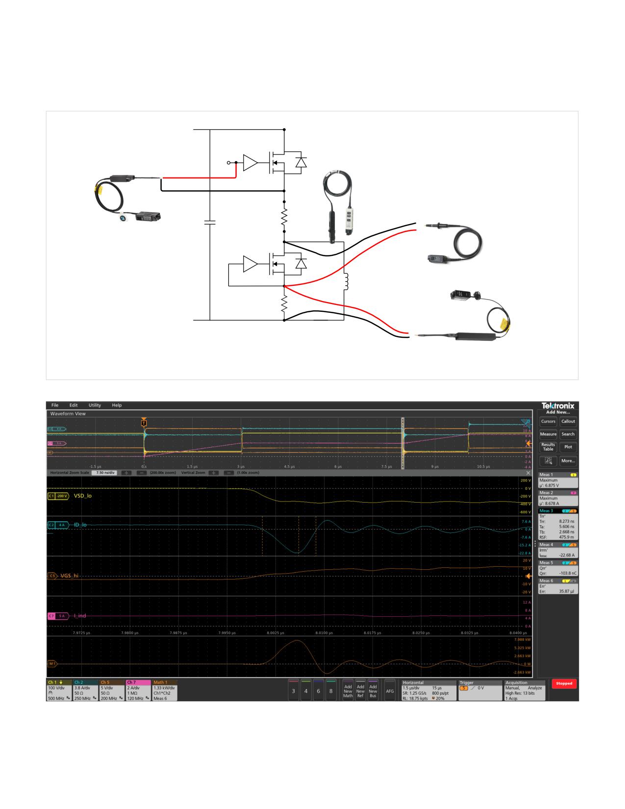
Probe connections are shown in Figure 30. Note that the voltage probe on Channel 1 is connected in the forward direction
across the low-side diode (VSD instead of VDS). The waveforms and captured measurements are shown in Figure 31.
VDD
Gate
Drive
I_ind: Channel 7
Vgs_hi: Channel 5
TCP0030A AC/DC
TIVP1 Isolated Current Probe
Current Probe
VSD_lo: Channel 1
TPP0850 Voltage Probe
(Earth Referenced)
CVR
Gate
Drive
Air Core
Inductor
CVR
ID_lo: Channel 2
TICP100 Isolated Current Probe
Figure 30. Example probe connections for reverse recovery measurements. Note that the high voltage measurement is from source to drain.
Figure 31: Reverse recovery waveforms and measurements.
The WBG-DPT application also allows multiple Trr measurements to be taken over more than one pulse. These
measurements can be displayed in an overlapped plot to observe changes in trr over multiple pulses.
22 | WWW.TEK.COM

Double Pulse Testing for Power Semiconductor Devices
APPLICATION NOTE
with an Oscilloscope and Arbitrary Function Generator
Conclusion
References
Double pulse testing is the preferred method for measuring
1.
switching parameters of power devices under a controlled
evolving-materials-and-testing-emerging- generations-
junction temperature. This application note has covered
power-electronics
the application of instrumentation, probes and application
2.
software to achieve high-quality, repeatable results.
measuring-power-supply-switching-loss-oscilloscope
Tektronix offers a wide range of instruments, probes and
3.
“Test Method for Continuous-Switching Evaluation of
software to address double pulse testing applications.
Gallium Nitride Power Conversion Devices”, JEDEC
Standard JEP182, Version 1.0, January 2021
Elektro-Automatik and Keithley power supplies
4.
Infineon: Double Pulse Test for IGBT & FWD - Principle
provide precise, reliable power without taking up
unnecessary space.
1311925659-501009.pdf
The AFG31000 with its Double Pulse Test application is
5.
quick and easy to set up, allowing engineers to focus on
datasheets-switching-parameters
gathering data.
6.
stfh10n60m2-974335.pdf
The WBG-DPT double pulse application on the 4, 5 or 6
Series B MSO is fully-integrated into the oscilloscope
7.
measurement system and automates testing with a wide
eval6498l.pdf
range of measurements, the ability to control an arbitrary
8.
function generator, and innovative deskew approach.
measurement-and-analysis
tests to analyze power devices’ behavior while saving
9.
time compared to manual testing. It defaults to industry-
measuring-vgs-wide-bandgap-semiconductors
standard measurements but can be customized as well.
Lastly, a range of oscilloscope probes, such as low-noise
--energy-loss-measurements
isolated voltage and current probes deliver high-fidelity
11.
signals to the oscilloscope.
solutions/wide-bandgap-double-pulse
As explained in this application note, these elements can be
12.
combined to greatly reduce test times and achieve faster
deskew-approach-accelerates-double-pulse-testing
time to market for designers of next generation power
13.
converters.
evaluation-kits/speedval-kit-modular-evaluation-
platform/
WWW.TEK.COM | 23

Contact Information:
Australia 1 800 709 465
Austria* 00800 2255 4835
Balkans, Israel, South Africa and other ISE Countries +41 52 675 3777
Belgium* 00800 2255 4835
Brazil +55 (11) 3530-8901
Canada 1 800 833 9200
Central East Europe / Baltics +41 52 675 3777
Central Europe / Greece +41 52 675 3777
Denmark +45 80 88 1401
Finland +41 52 675 3777
France* 00800 2255 4835
Germany* 00800 2255 4835
Hong Kong 400 820 5835
India 000 800 650 1835
Indonesia 007 803 601 5249
Italy 00800 2255 4835
Japan 81 (3) 6714 3086
Luxembourg +41 52 675 3777
Malaysia 1 800 22 55835
Mexico, Central/South America and Caribbean 52 (55) 88 69 35 25
Middle East, Asia, and North Africa +41 52 675 3777
The Netherlands* 00800 2255 4835
New Zealand 0800 800 238
Norway 800 16098
People’s Republic of China 400 820 5835
Philippines 1 800 1601 0077
Poland +41 52 675 3777
Portugal 80 08 12370
Republic of Korea +82 2 565 1455
Russia / CIS +7 (495) 6647564
Singapore 800 6011 473
South Africa +41 52 675 3777
Spain* 00800 2255 4835
Sweden* 00800 2255 4835
Switzerland* 00800 2255 4835
Taiwan 886 (2) 2656 6688
Thailand 1 800 011 931
United Kingdom / Ireland* 00800 2255 4835
USA 1 800 833 9200
Vietnam 12060128
* European toll-free number. If not
accessible, call: +41 52 675 3777
Rev. 02.2022
Find more valuable resources at TEK.COM
Copyright © Tektronix. All rights reserved. Tektronix products are covered by U.S. and foreign patents, issued and pending. Information in this publication supersedes that
in all previously published material. Specification and price change privileges reserved. TEKTRONIX and TEK are registered trademarks of Tektronix, Inc. All other trade names
referenced are the service marks, trademarks or registered trademarks of their respective companies.
040725 75W-61623-4