Introduction
DC-DC converters are widely used electronic components that convert DC power from one voltage level to another while regulating the output voltage. The output provides a constant voltage to a circuit, regardless of variations in the input voltage or the load current. These power management devices are used in a wide variety of electronic products, including laptops, mobile phones, and instrumentation.
Given the increased pressure to develop products that consume less power and have longer battery life, design engineers need to achieve higher power conversion efficiencies. As a result, numerous measurements are required to characterize the electrical parameters of DC-DC converters. The tests performed include line regulation, load regulation, input and output voltage accuracy, quiescent current, efficiency, turn-on time, ripple, and transient response. Some of these tests require DC test instruments for sourcing and measuring; others require an oscilloscope, and some may require both.
This application note explains how to simplify DC-DC converter testing using a Keithley two-channel Series 2600B System SourceMeter SMU Instrument and a Tektronix MSO/
DPO-5000 or DPO-7000 Series Oscilloscope. The DPOPWR Application Software developed for these scopes supports measurement and analysis of common power management device parameters. Figure 1 illustrates a typical configuration for testing DC-DC converters.
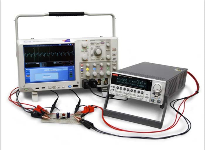
Figure 1. Complete solution: MSO-5204 scope and 2612B two-channel SMU for testing DC-DC converter circuits.
The DC-DC Converter
DC-DC converters are useful for generating output voltages that are either higher or lower than the input voltage. A step-down (or buck) converter produces an output voltage lower than the input voltage; a step-up (or boost) converter produces an output voltage higher than the input voltage. Ideally, this conversion should be performed with high efficiency to avoid wasting energy. Figure 2 is a simplified diagram of a DC-DC converter. The VIN terminal is the input voltage node of the device, which is referenced to the common GND terminal. The VOUT terminal is the regulated voltage output with respect to the common terminal.
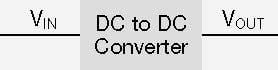
Figure 2. Simplified diagram of DC-DC converter.
Using Series 2600B SMUs for DC-DC Converter Parameter Testing
Typically, electrical characterization of DC-DC converters involves sourcing and measuring input voltage (VIN), measuring input current (IIN), measuring the output voltage
(VOUT), and sinking a load current (IOUT). From these measurements, the efficiency and other parameters can be determined. The efficiency is important for most designs, especially battery-powered products, because it directly affects the running time of the device. The efficiency of a converter is the output power divided by the input power.
Traditionally, the DC characterization of these devices required the use of a couple of digital multimeters, a DC power supply, and an electronic load. However, the DC characterization can be simplified by replacing all of these electronic instruments with a single two-channel Series 2600B System SourceMeter SMU. SMUs are ideal for testing a wide variety of I-V parameters of DC-DC converters because they can source and measure both current and voltage, as well as function as an electronic load. Using one instrument rather than multiple units simplifies the test implementation, software, and synchronization, as well as taking up less rack or bench space.
As shown in Figure 3, using one SMU channel (CH1) on the input terminal and another SMU channel (CH2) on the output terminal of the DC-DC converter replaces several instruments.
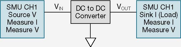
Figure 3. Parameter testing a DC-DC converter using two SMUs.
Although DC-DC converter characterization involves testing many electrical parameters, load regulation and line regulation are discussed in more detail because these are very common tests.
Load Regulation
Load regulation tests characterize a DC-DC converter’s ability to maintain the specified output voltage as the load current
(ILOAD) varies under a constant input voltage (VIN). The load regulation test is typically performed over the entire range of load currents.
Figure 4 shows a typical load regulation test using two SMU channels. SMU CH1 supplies the input voltage and monitors the input current. SMU CH2 is configured as an electronic load by setting it to sink current (source a negative current). In this mode, the Series 2600B SMU will operate in the fourth quadrant and sink current.
The SMUs are configured using the remote sense, or fourwire, connection. Using a four-wire connection eliminates the lead resistance that would otherwise affect measurement accuracy. With the four-wire method, the source outputs using one pair of test leads (between Output HI and Output LO), and the voltage drop is measured across a second set of leads (across Sense HI and Sense LO). The sense leads should be connected as close to the device as possible to ensure the lead resistance is not added to the measurement.
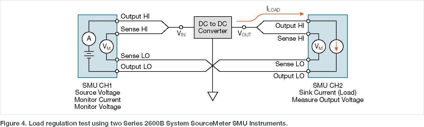
Figure 5 shows the results of a typical load regulation test. In this particular example, the DC-DC converter was configured to output a constant 3.6V. SMU CH1 was set to bias 5V (nominal value) to the voltage input terminal. SMU CH2 was configured to sweep a load current from 0 to –1A and measure the resulting output voltage. These measurements were taken under the control of the embedded TSP® Express software, which enables quick and easy I-V testing. Users can easily calculate the load regulation percentage from the I-V data.
|
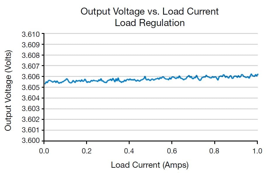 |
Figure 5. Plot of DC-DC converter load regulation using a two-channel 2612B SourceMeter SMU Instrument.
Line Regulation
Line regulation is the ability of a DC-DC converter to maintain the specified output voltage as the input voltage is varied. The output voltage should remain constant, within a few millivolts, while the input voltage is varied over the specified voltage input range.
For the line regulation test, both SMUs are connected to the DC-DC converter in the same way they were for the load regulation test. However, for this test, the input voltage is swept over the specified input voltage range and the output voltage is measured. The load current is typically set to 0A.
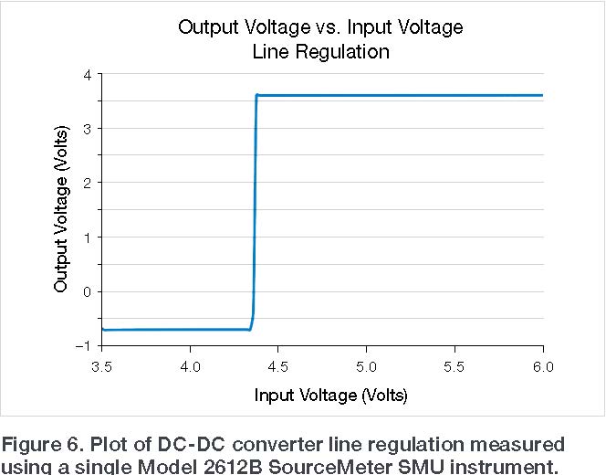
Figure 6 shows the result from a typical line regulation test. This test was performed using a Model 2612B SMU. One channel of the Model 2612B (SMU CH1) was configured to sweep voltage on the input terminal of the device. The second channel of the SMU (SMU CH2) was configured to measure the output voltage. From the I-V data, the line regulation percentage can be easily calculated.
DPO-7000 Series Scope for DC-DC Converter Testing
In addition to the DC parameter testing performed by the SMUs, some DC-DC converter tests require the use of an oscilloscope. These AC tests include measuring the turn-on time, ripple, spectral analysis, and transient response. For many of the scope tests, the SMUs can provide the input voltage and the load current. Figure 7 illustrates a typical test configuration showing both the SMUs and the scope connected to the device. The particular scope probes used depend on the device and the complete test circuit.
To simplify device testing, the scope’s optional DPOPWR Application Software provides automated power measurements and analysis for DC-DC converters, AC-DC converters, power supplies and other power management devices. This software, when used with a Tektronix MSO/ DPO-5000 or DPO-7000 Series Scope, can provide common power measurement device measurements and calculations for magnetic, electrical, and input/output analysis. The following example tests for turn-on time and spectral analysis of the DC-DC converter can help illustrate the capabilities of this software.
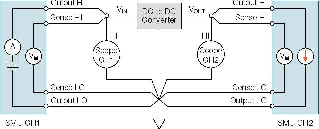
Figure 7. Testing a non-isolated DC-DC converter using both a scope and two SMUs.
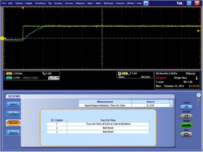 |
Figure 8. Screenshot of turn-on time test of DPOPWR software on MSO-5000 scope displaying the measured turn-on time (highlighted in red) .
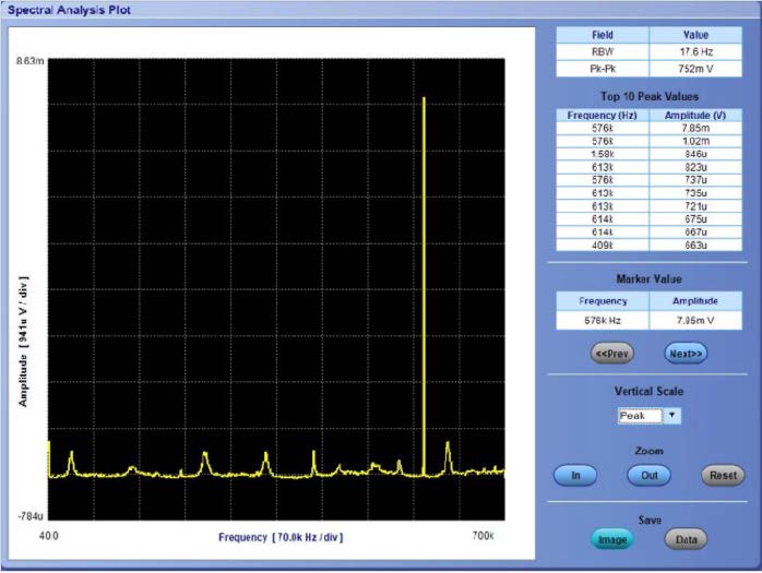
Figure 9. Spectral analysis plot of DC-DC converter.
Turn-On Time
One of the built-in tests of the DPOPWR application software is determining the turn-on time of the DC-DC converter. The turn-on time test measures the time delay between when the input voltage is applied to the system and the time it takes to develop the steady output voltage.
For this particular test, SMU CH1 of the Model 2612B applied the input voltage and Channel 1 (CH1) of the scope was connected across the input of the DC-DC converter.
Figure 8 shows the time-based measurement result. Note that, in addition to the time-based graphical result at the top of the screen, in the Results tab of the DPOPWR software, the turn-on time was automatically calculated and displayed, providing repeatable measurements, and eliminating the need for the user to measure the time on the screen manually.
Spectral Analysis
Another built-in test function, the spectral analysis feature, allows analyzing the unwanted AC components of the output voltage and measuring output noise/ripple in the frequency domain. The spectral analysis test analyzes, measures, and displays the AC component of a signal based on the selected Start, Stop and bandwidth values.
To generate a spectral analysis plot of the DC-DC converter, the Model 2612B supplied the input voltage. Channel 1 (CH1) of the scope was connected to the device input, and Channel 2 (CH2) was connected to the device output. The resulting spectral analysis plot of a DC-DC converter is shown in Figure 9. This software plots the voltage amplitude as a function of frequency and displays the top peak values in a chart on the screen. This measurement indicates several millivolts of switching frequency ripple on the DC output voltage.
Detailed information on the DPOPWR application software is available in the Tektronix application note, “Power Supply Measurement and Analysis with DPOPWR Application Software.
Conclusion
Testing DC-DC converters traditionally required several test instruments. However, a single two-channel Series 2600B System SourceMeter SMU Instrument simplifies electrical characterization of DC-DC converters because it combines multiple measurement instruments into one unit. Combining the two-channel Series 2600B SMU instrument with a MSO/DPO-5000 or DPO-7000 Series Scope makes a more complete solution for providing testing and analysis of DC-DC converters.