Dielectric Types
Capacitors are very important in all areas of electronics.From timing circuits to sample and hold applications, we depend on capacitors to act in a nearly ideal fashion. In many cases, however, complex electrochemical interactions cause capacitors to fall short of perfect.
One of the less ideal properties that a capacitor has is leakage, or insulation resistance (IR). For a given dielectric material, the effective parallel resistance is inversely proportional to the capacitance. This is because the resistance is proportional to the thickness of the dielectric, and inverse to the capacitive area. The capacitance is proportional to the area and inverse to the separation. Thus, a common unit for qualification of capacitor leakage is the product of its capacitance and leakage resistance,usually in megohm-microfarads (MΩ·µF).
Dielectric Types
For polymer dielectrics such as polystyrene, polycarbonate or Teflon®, the insulation resistance can range from 104 MΩ·µF to 108 MΩ·µF, depending on the materials and their purity. For example, a 1000pF Teflon cap with insulation resistance greater than 1017Ω is specified as >108 MΩ·µF. For various ceramics such as X7R or NPO, insulation resistance can range from 103 MΩ·µF to 106 MΩ·µF. Electrolytic capacitors such as tantalum or aluminum have much lower leakage resistances, in the region from 1MΩ·µF to 100MΩ·µF. For example, a 4.7µF aluminum cap specified as 50MΩ·µF is guaranteed to have at least 10.6MΩ insulation resistance.
Typical Test Method
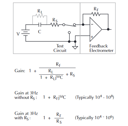
When measuring extremely low leakage capacitors, there are a number of things to keep in mind. Normally, a feedback electrometer would be used as shown in Figure 1. The series resistor (RS) in the measurement loop is necessitated by noise considerations. Without the resistor, an electrometer in this configuration would have a very high noise gain at high frequencies. This noise amplification is unacceptable. The series resistor limits the AC noise to a maximum level, although it does make the measurement more complex. Since RS appears in the denominator of the simplified gain equation for 3Hz, a larger resistance decreases the AC noise gain. To make a measurement to 0.1%, the series resistor must be less than 0.1% of the insulation resistance to be measured. Thus, the resistor should be as large as possible to improve noise, yet small enough to avoid introducing errors in the final result. This trade-off requires knowing the approximate value of the insulation resistance, even before the measurement has been made. Even then, finding the optimum value for the series resistor can be difficult, especially when a variety of capacitors are to be tested.
Second, the resistor adds noise to the measurement.Johnson noise is thermal noise created by any resistor. At room temperature this is roughly 6.5 × 10⁻¹⁰ √∆f/R amps, p-p. The current noise in a 1TΩ feedback resistor at a typical 3Hz bandwidth would be ~8×10-16A. When measuring an insulation resistance of 1016Ω at 10V, the noise current will be 80% of the measured current.
Alternate Test Circuit
Even better results will be obtained with the circuit of Figure 2. The added resistance of diode DS allows RS to be reduced to approximately 100kΩ. At the beginning of the capacitor charge cycle, the current through the diode is relatively high and the equivalent resistance of the diode is low, allowing the capacitor to charge quickly. As the capacitor becomes charged, the current will decrease steadily and the diode resistance will increase, limiting the noise amplification automatically.
Typically, the diode can be a small-signal diode, such as the 1N914 or the 1N3595. Note some series resistance is still required to prevent overload in case the capacitor is shorted.
The diode should be enclosed in a light tight metal enclosure to eliminate photo-electric as well as electrostatic interference.
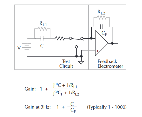
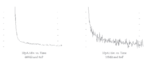
Figure 3 show some typical response curves using different series resistors.
Implementation
The 6517A Electrometer offers several advantages when measuring capacitor leakage.
- The 6517A contains a low noise, variable 1kV voltage source for making high resistance measurements, with built-in current limiting. For a given capacitor, a larger applied voltage within the voltage rating of the capacitor, will give a larger leakage current. Measuring a larger current with the same intrinsic noise floor produces a greater signal-to-noise ratio, and a more accurate reading.For capacitors with high voltage ratings, a 1000V source is supplied. Because the voltage source is continuously variable, voltage coefficients are easily obtained.
- Temperature and humidity can have a significant effect on high resistance measurements. It therefore becomes important to regulate and measure these quantities. For test sequences involving required environmental conditions, the 6517A has the ability to simultaneously monitor temperature and humidity. This provides a record of conditions, and allows for easier determination of temperature coefficients.Automatic time stamping of readings provides a further record of time-resolved measurements.
- An optional switch card will allow repeated testing of up to 10 capacitors to facilitate small batch testing for the laboratory environment.
- The V/I mode simplifies the task of making a single measurement. In this mode a resistance reading of V/I is displayed, using its output voltage and measured current reading. When setting up a measurement system, it is convenient to have readings in a form that requires no interpretation. This is helpful when using the instrument without a computer interface.
Test Circuits
For statistical purposes, a quantity of capacitors must be tested to produce useful data. Obviously, it is impractical to perform these tests manually, so some sort of automated test system is required.Figure 4 illustrates such a system, which employs a Model 6517A Electrometer/Source, Model 7158 Low Current Scanner Cards, and Model 7169A Form C Switch Cards.The cards must be installed in a switching mainframe, such as a Model 7002. A computer controls the instruments to perform the tests automatically.
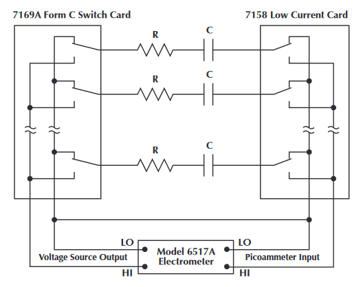
In this test system, a single instrument, the Model 6517A, provides both the voltage sourcing and low current measurement functions. This instrument is particularly useful for this application because it can display either resistance or leakage current and will source up to 1000V DC. Due to the limitation of the Model 7169A card, the amount of voltage sourced should not exceed 500V. If the maximum test voltage is only 110V, the 7169A card can be replaced with the Model 7111 Form C Switch Card.
One set of switches is used to apply the test voltage to each capacitor in turn; a second set of switches connects each capacitor to the picoammeter after a suitable soak period. This system tests up to ten capacitors but is easily expanded to any reasonable number.
After the capacitors have been tested, the voltage source should be set to zero and some time allowed to discharge the capacitors before they are removed from the fixture. Note that in Figure 4 the capacitors have a discharge path through the normally closed contacts of the relays.
To prevent electric shock, test connections must be configured such that the user cannot come in contact with the conductors, connections, or the DUT. Safe installation requires proper shielding, barriers, and grounding to prevent contact with conductors.
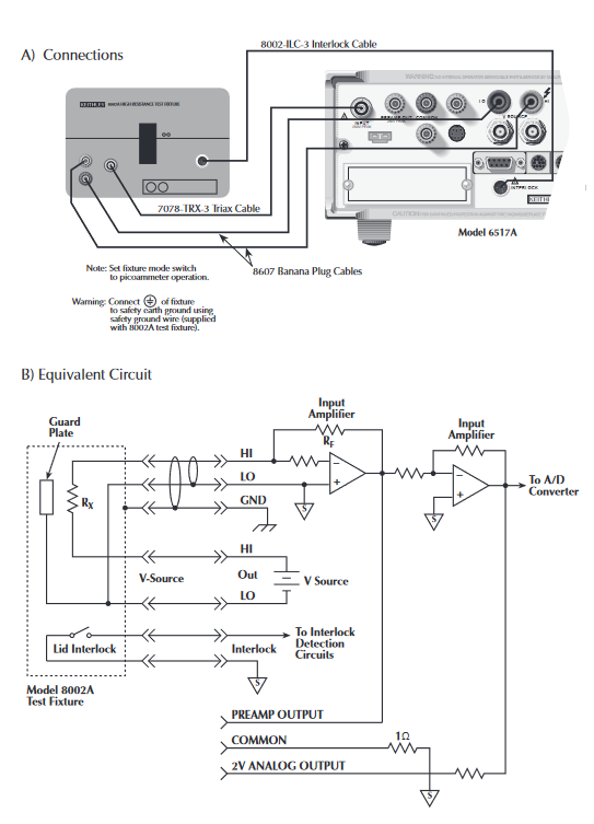
For single capacitor testing, the Model 8002A High Resistance Test Fixture can be used with the 6517A. The Model 8002A has been specifically designed to minimize leakage currents that can become a significant portion of a high resistance measurement if not controlled.
Connections to the 8002A from the 6517A are shown in Figure 5. Note that the 8002A requires the use of a 8002-ILC3 Interlocking Cable. The interlock feature of the 6517A and 8002A prevents voltage from the 6517A from being applied when the lid of the 8002A is open. However, once a capacitor has been charged to a high voltage, the capacitor should be discharged prior to any handling and removal from the fixture in order to prevent any electrical shock hazards.
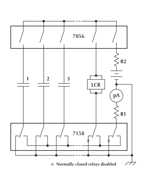
More complex test systems are possible, combining the leakage measurement with capacitance measurements, dielectric absorption and other tests, if desired. A simplified schematic of such a test system using an LCZ bridge and a picoammeter with a voltage source is shown in Figure 6.
Example Program and Description
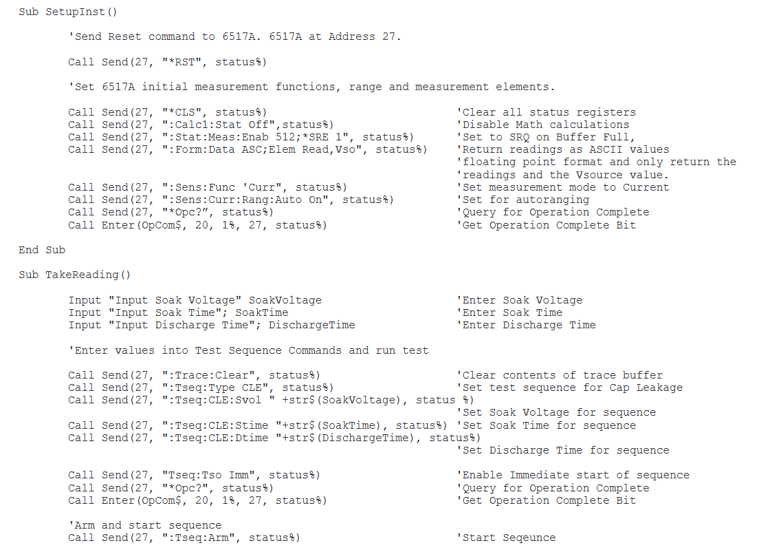
An example computer program is shown in Figure 7. This example program illustrates the programming of the 6517A using the built-in test sequence, Capacitor Leakage Test, of the 6517A that provides a capacitor leakage measurement.
Refer to the program listing for the following program description.
After the 6517A has been cleared, the instrument is configured for the following functions:
- Math calculations turned off.
- 6517A set to SRQ when buffer is full.
- Retun ASCII data for the leakage current reading and the Voltage Source value.
- Set the 6517A to measure current.
- Set the 6517A for autoranging.
Once these commands are issued, the program checks to see if the operation has been completed prior to sending any further commands. This gives the 65l7A the appropriate amount of time to be configured.
After the initial setup, the operator is then prompted for the desired soak voltage, the soak time, and the discharge time. The discharge time allows the capacitor to be discharged so that it may be handled. With these values entered, the program then sends the test sequence commands to the 6517A with the prompted values for the test. Again, once these commands are issued, the program checks to see if the operation has been completed prior to sending any further commands. This gives the 6517A the appropriate amount of time to be configured.
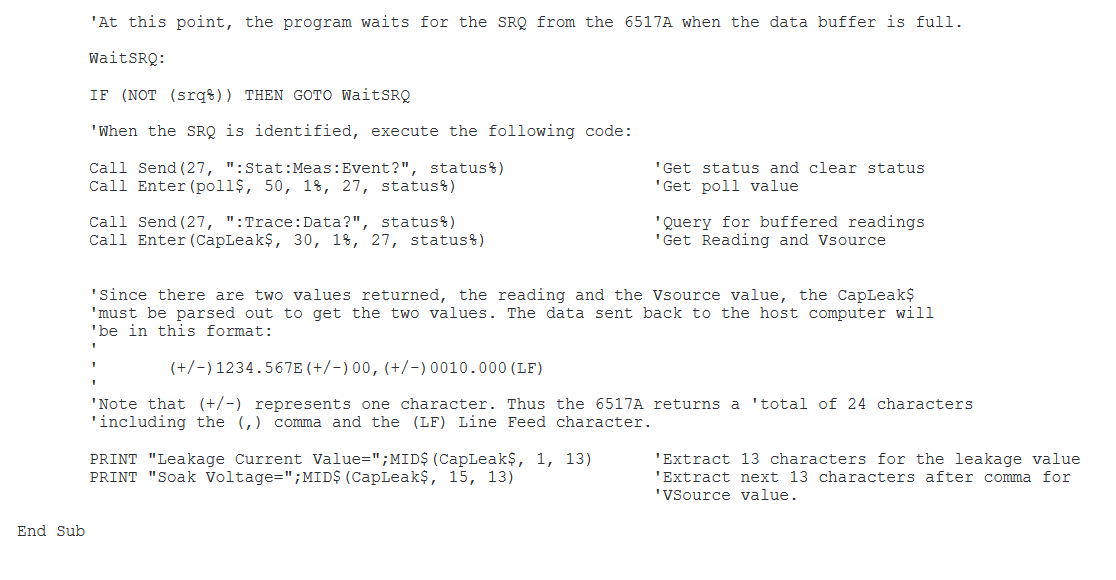
When the operation complete function has been satisfied, the program then arms the test sequence to begin the test. During the testing phase, the computer program waits for the SRQ to be identified when the data buffer has been filled. When the SRQ has been identified, the program reads the measurement status register. This action clears the SRQ from the status register.Clearing the SRQ is important, especially if the test is run again.In addition to clearing the status register, getting the data from the buffer clears the event that caused the SRQ.
The data is obtained and placed into the variable CapLeak$.Because the data is returned in ASCII format and there are two values associated with the single capacitor leakage current value, the string must be parsed in order to separate the current reading and the voltage source values. As shown in the example, BASIC uses the MIDS$ function to obtain a subset of the string.
Although this example was written with using BASIC in mind, the program can be modified for Visual Basic, C, TestPoint, LabVIEW, or any other programming environment that supports GPIB communication with instruments. Examples in TestPoint and LabVIEW are available from Keithley at www.keithley.com.
Test System Safety
Many electrical test systems or instruments are capable of measuring or sourcing hazardous voltage and power levels. It is also possible, under single fault conditions (e.g., a programming error or an instrument failure), to output hazardous levels even when the system indicates no hazard is present.
These high voltage and power levels make it essential to protect operators from any of these hazards at all times. Protection methods include:
- Design test fixtures to prevent operator contact with any hazardous circuit.
- Make sure the device under test is fully enclosed to protect the operator from any flying debris.
- Double insulate all electrical connections that an operator could touch. Double insulation ensures the operator is still protected, even if one insulation layer fails.
- Use high-reliability, fail-safe interlock switches to disconnect power sources when a test fixture cover is opened.
- Where possible, use automated handlers so operators do not require access to the inside of the test fixture or have a need to open guards.
- Provide proper training to all users of the system so they understand all potential hazards and know how to protect themselves from injury.
It is the responsibility of the test system designers, integrators, and installers to make sure operator and maintenance personnel protection is in place and effective.
Find more valuable resources at TEK.COM
Copyright © Tektronix. All rights reserved. Tektronix products are covered by U.S. and foreign patents, issu ed and pending. Information in this publication supersedes that in all previously published material. Specification and price change privileges reserved. TEKTRONIX and TEK are registered trademarks of Tektronix, Inc. All other trade names referenced are the service marks, trademarks or registered trademarks of their respective companies.
No.1682 8012KDCI