
Introduction To SONET
SONET (Synchronous Optical NETwork) is a standard for optical telecommunications transport. It was formulated by the Exchange Carriers Standards Association (ECSA) for the American National Standards Institute (ANSI), which sets industry standards in the U.S. for telecommunications and other industries. The comprehensive SONET/SDH standard is expected to provide the transport infrastructure for worldwide telecommunications for at least the next two or three decades.
The increased configuration flexibility and bandwidth availability of SONET provides significant advantages over the older telecommunications system. These advantages include:
- Reduction in equipment requirements and an increase in network reliability
- Provision of overhead and payload bytes – the overhead bytes permit management of the payload bytes on an individual basis and facilitate centralized fault sectionalization
- Definition of a synchronous multiplexing format for carrying lower level digital signals (such as DS1, DS3) and a synchronous structure which greatly simplifies the interface to digital switches, digital cross-connect switches, and add-drop multiplexers
- Availability of a set of generic standards which enable products from different vendors to be connected
- Definition of a flexible architecture capable of accommodating future applications, with a variety of transmission rates
In brief, SONET defines optical carrier (OC) levels and electrically equivalent synchronous transport signals (STSs) for the fiber-optic based transmission hierarchy
Background
Before SONET, the first generations of fiber optic systems in the public telephone network used proprietary architectures, equipment, line codes, multiplexing formats, and maintenance procedures. The users of this equipment – Regional Bell Operating Companies and inter-exchange carriers (IXCs) in the U.S., Canada, Korea, Taiwan, and Hong Kong – wanted standards so they could mix and match equipment from different suppliers. The task of creating such a standard was taken up in 1984 by the Exchange Carriers Standards Association (ECSA) to establish a standard for connecting one fiber system to another. This standard is called SONET for Synchronous Optical NETwork.
Synchronization of Digital Signals
To correctly understand the concepts and details of SONET, it’s important to be clear about the meaning of Synchronous, Asynchronous, and Plesiochronous.
In a set of Synchronous signals, the digital transitions in the signals occur at exactly the same rate. There may, however, be a phase difference between the transitions of the two signals, and this would lie within specified limits. These phase differences may be due to propagation time delays or jitter introduced into the transmission network. In a synchronous network, all the clocks are traceable to one Stratum 1 Primary Reference Clock (PRC). The accuracy of the PRC is better than ±1 in 1011 and is derived from a cesium atomic standard.
If two digital signals are Plesiochronous, their transitions occur at “almost” the same rate, with any variation being constrained within tight limits. For example, if two networks need to interwork, their clocks may be derived from two different PRCs. Although these clocks are extremely accurate, there is a difference between one clock and the other. This is known as a plesiochronous difference.
In the case of Asynchronous signals, the transitions of the signals do not necessarily occur at the same nominal rate. Asynchronous, in this case, means that the difference between two clocks is much greater than a plesiochronous difference. For example, if two clocks are derived from free-running quartz oscillators, they could be described as asynchronous.
Basic SONET Signal
SONET defines a technology for carrying many signals of different capacities through a synchronous, flexible, optical hierarchy. This is accomplished by means of a byte-interleaved multiplexing scheme.Byte-interleaving simplifies multiplexing, and offers end-to-end network management.
The first step in the SONET multiplexing process involves the generation of the lowest level or base signal. In SONET, this base signal is referred to as Synchronous Transport Signal level-1, or simply STS-1, which operates at 51.84 Mb/s. Higher-level signals are integer multiples of STS-1, creating the family of STS-N signals in Table 1. An STS-N signal is composed of N byte-interleaved STS-1 signals. This table also includes the optical counterpart for each STS-N signal, designated OC-N (Optical Carrier level-N).
Synchronous and Non-synchronous line rates and the relationships between each are shown in Tables 1 and 2.
Table 1. SONET Hierarchy
| Signal | Bit Rate | Capacity |
| STS-1, OC-1 | 51.840 Mb/s | 28 DS1s or 1 DS3 |
| STS-3, OC-3 | 155.520 Mb/s | 84 DS1s or 3 DS3s |
| STS-12, OC-12 | 622.080 Mb/s | 336 DS1s or 12 DS3s |
| STS-48, OC-48 | 2488.320 Mb/s | 1344 DS1s or 48 DS3s |
| STS-192, OC-192 | 9953.280 Mb/s | 5376 DS1s or 192 DS3s |
| STS-768, OC-768 | 39813.12 Mb/s | 21504 DS1s or 768 DS3s |
STS = Synchronous Transport Signal
OC = Optical Carrier
Table 2. Non-Synchronous H ierarchy
| Signal | Bit Rate | Channels |
| DS0 | 64 kb/s | 1 DS0 |
| DS1 | 1.544 Mb/s | 24 DS0s |
| DS2 | 6.312 Mb/s | 96 DS0s |
| DS3 | 44.736 Mb/s | 28 DS1s |
Why Synchronize?
Synchronous versus Asynchronous
Traditionally, transmission systems have been asynchronous, with each terminal in the network running on its own clock. In digital transmission, “clocking” is one of the most important considerations. Clocking means using a series of repetitive pulses to keep the bit rate of data constant and to indicate where the ones and zeroes are located in a data stream.
Since these clocks are totally free-running and not synchronized, large variations occur in the clock rate and thus the signal bit rate. For example, a DS3 signal specified at 44.736 Mb/s + 20 ppm (parts per million) can produce a variation of up to 1789 bps between one incoming DS3 and another.
Asynchronous multiplexing uses multiple stages. Signals such as asynchronous DS1s are multiplexed, extra bits are added (bit-stuffing) to account for the variations of each individual stream, and are combined with other bits (framing bits) to form a DS2 stream. Bit-stuffing is used again to multiplex up to DS3. DS3s are multiplexed up to higher rates in the same manner. At the higher asynchronous rate, they cannot be accessed without demultiplexing.
In a synchronous system, such as SONET, the average frequency of all clocks in the system will be the same (synchronous) or nearly the same (plesiochronous). Every clock can be traced back to a highly stable reference supply. Thus, the STS-1 rate remains at a nominal 51.84 Mb/s, allowing many synchronous STS-1 signals to be stacked together when multiplexed without any bit-stuffing. Thus, the STS-1s are easily accessed at a higher STS-N rate.
Low-speed synchronous virtual tributary (VT) signals are also simple to interleave and transport at higher rates. At low speeds, DS1s are transported by synchronous VT-1.5 signals at a constant rate of 1.728 Mb/s. Single-step multiplexing up to STS-1 requires no bit stuffing and VTs are easily accessed.
Pointers accommodate differences in the reference source frequencies and phase wander, and prevent frequency differences during synchronization failures.
Synchronization Hierarchy
Digital switches and digital cross-connect systems are commonly employed in the digital network synchronization hierarchy. The network is organized with a master-slave relationship with clocks of the higherlevel nodes feeding timing signals to clocks of the lower-level nodes. All nodes can be traced to a primary reference source, a Stratum 1 atomic clock with extremely high stability and accuracy. Less stable clocks are adequate to support the lower nodes.
Synchronizing SONET
The internal clock of a SONET terminal may derive its timing signal from a Building Integrated Timing Supply (BITS) used by switching systems and other equipment. Thus, this terminal will serve as a master for other SONET nodes, providing timing on its outgoing OC-N signal. Other SONET nodes will operate in a slave mode called “loop timing” with their internal clocks timed by the incoming OC-N signal. Current standards specify that a SONET network must be able to derive its timing from a Stratum 3 or higher clock.
Frame Format Structure
SONET uses a basic transmission rate of STS-1 – equivalent to 51.84 Mb/s. Higher-level signals are integer multiples of the base rate. For example, STS-3 is three times the rate of STS-1 (3 x 51.84 = 155.52 Mb/s). An STS-12 rate would be 12 x 51.84 = 622.08 Mb/s.
STS-1 Building Block
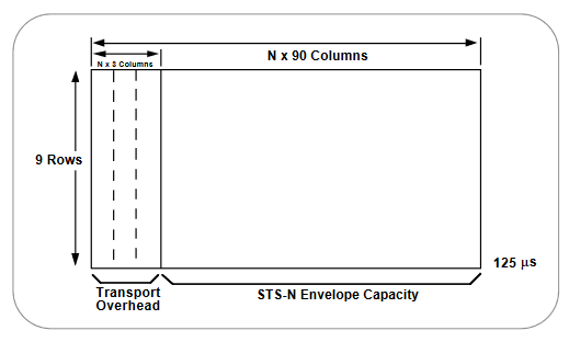
The frame format of the STS-1 signal is shown in Figure 1. In general,the frame can be divided into two main areas: Transport overhead and the Synchronous Payload Envelope (SPE).
The synchronous payload envelope can also by divided into two parts: STS path overhead and the payload. The payload is the revenue-producing traffic being transported and routed over the SONET network. Once the payload is multiplexed into the synchronous payload envelope, it can be transported and switched through SONET without having to be examined and possibly demultiplexed at intermediate nodes. Thus, SONET is said to be service-independent or transparent.
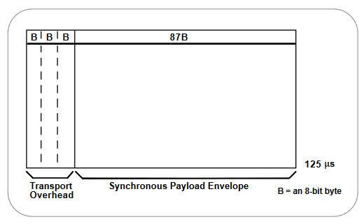
Transport Overhead is composed of section overhead and line overhead.The STS-1 path overhead is part of the synchronous payload envelope.
The STS-1 payload has the capacity to transport up to:
- 28 DS1s
- 1 DS3
- 21 2.048 Mb/s signals or combinations of the above.
STS-1 Frame Structure
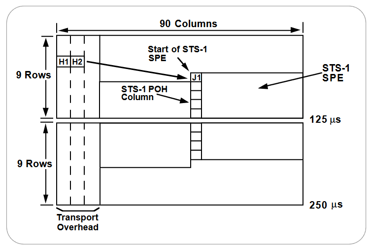
STS-1 is a specific sequence of 810 bytes (6480 bits), which includes various overhead bytes and an envelope capacity for transporting payloads. It can be depicted as a 90 column by 9 row structure. With a frame length of 125 µs (8000 frames per second), STS-1 has a bit rate of 51.840 Mb/s. The order of transmission of bytes is row-by-row from top to bottom, left to right (most significant bit first).
As shown in Figure 1, the first three columns of the STS-1 frame are for the Transport Overhead. The three columns each contain nine bytes. Of these, nine bytes are overhead for the Section layer (for example, Section Overhead), and 18 bytes are overhead for the Line layer (for example, Line Overhead). The remaining 87 columns constitute the STS-1 Envelope Capacity (payload and path overhead).
As stated before, the basic signal of SONET is the Synchronous Transport Signal level 1, or STS-1. The STS frame format is composed of 9 rows of 90 columns of 8-bit bytes, or 810 bytes. The byte transmission order is row-by-row, left to right. At a rate of 8000 frames per second, that works out to a rate of 51.840 Mb/s, as the following equation demonstrates:
9 x 90 bytes/frame x 8 bits/byte x 8000 frames/s = 51,840,000 bits/s = 51.840 Mb/s
This is known as the STS-1 signal rate – the electrical rate used primarily for transport within a specific piece of hardware. The optical equivalent of STS-1 is known as OC-1, and it’s used for transmission across the fiber.
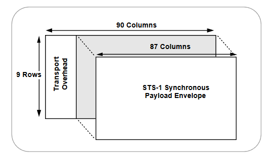
The STS-1 frame consists of overhead, plus a Synchronous Payload Envelope (see Figure 2). The first three columns of each STS-1 frame make up the Transport Overhead, and the last 87 columns make up the SPE. SPEs can have any alignment within the frame, and this alignment is indicated by the H1 and H2 pointer bytes in the line overhead.
STS-1 Envelope Capacity and Synchronous Payload Envelope (SPE)
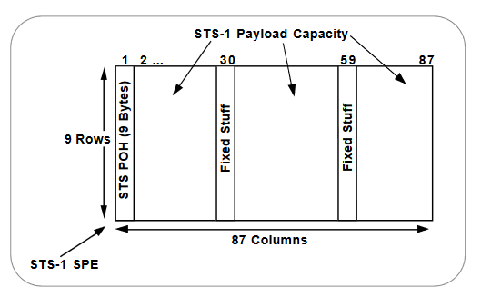
Figure 3 depicts the STS-1 SPE, which occupies the STS-1 Envelope Capacity. The STS-1 SPE consists of 783 bytes, and can be depicted as an 87 column by 9 row structure. Column 1 contains nine bytes, designated as the STS Path Overhead (POH). Two columns (columns 30 and 59) are not used for payload, but are designated as the “fixed stuff” columns. The 756 bytes in the remaining 84 columns are designated as the STS-1 Payload Capacity.
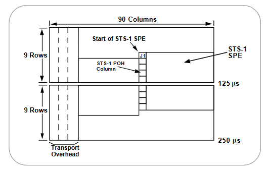
STS-1 SPE in Interior of STS-1 Frames
The STS-1 SPE may begin anywhere in the STS-1 Envelope Capacity (see Figure 4). Typically, it begins in one STS-1 frame and ends in the next. The STS Payload Pointer contained in the Transport Overhead designates the location of the byte where the STS-1 SPE begins.
STS POH is associated with each payload and is used to communicate various information from the point where a payload is mapped into the STS-1 SPE to where it’s delivered.
STS-N Frame Structure
An STS-N is a specific sequence of N x 810 bytes. The STS-N is formed by byte-interleaving STS-1 modules (see Figure 5). The Transport Overhead of the individual STS-1 modules are frame aligned before interleaving, but the associated STS SPEs are not required to be aligned because each STS-1 has a Payload Pointer to indicate the location of the SPE (or to indicate concatenation).
Overheads
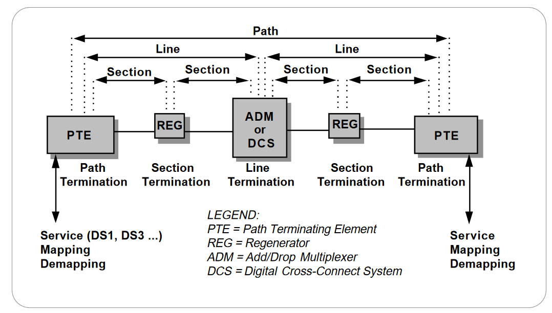
SONET provides substantial overhead information, allowing simpler multiplexing and greatly expanded OAM&P (Operations, Administration, Maintenance, and Provisioning) capabilities. The overhead information has several layers, which are shown in Figure 6. Path-level overhead is carried from end-to-end; it’s added to DS1 signals when they are mapped into virtual tributaries and for STS-1 payloads that travel end-to-end. Line overhead is for the STS-N signal between STS-N multiplexers. Section overhead is used for communications between adjacent network elements, such as regenerators.
Enough information is contained in the overhead to allow the network to operate and allow OAM&P communications between an intelligent network controller and the individual nodes.
The following sections detail the different SONET overhead information:
- Section Overhead
- Line Overhead
- STS Path Overhead
- VT Path Overhead
Section Overhead
Section Overhead contains nine bytes of the transport overhead accessed, generated, and processed by section-terminating equipment.This overhead supports functions such as:
- Performance monitoring (STS-N signal)
- Local orderwire
- Data communication channels to carry information for OAM&P
- Framing
This might be two regenerators, line terminating equipment, and a regenerator, or two line terminating equipment. The Section Overhead is found in the first three rows of Columns 1 through 9 (see Figure 7).Table 3 shows Section Overhead byte-by-byte.
Line Overhead
Line Overhead contains 18 bytes of overhead accessed, generated,and processed by line terminating equipment. This overhead supports functions such as:
- Locating the SPE in the frame
- Multiplexing or concatenating signals
- Performance monitoring
- Automatic protection switching
- Line maintenance
The Line Overhead is found in Rows 4 to 9 of Columns 1 through 9 (see Figure 8). Table 4 shows Line Overhead byte-by-byte.
Table 3. Section Overhead
| Byte | Description |
| A1 and A2 | Framing bytes – These two bytes indicate the beginning of an STS-1 frame. |
| J0 | Section Trace (J0)/Section Growth (Z0) – The byte in each of the N STS-1s in an STS-N that was formerly defined as the STS-1 ID (C1) byte has been refined either as the Section Trace byte (in the first STS-1 of the STS-N), or as a Section Growth byte (in the second through Nth STS-1s). |
| B1 | Section bit interleaved parity code (BIP-8) byte – This is a parity code (even parity) used to check for transmission errors over a regenerator section. Its value is calculated over all bits of the previous STS-N frame after scrambling, then placed in the B1 byte of STS-1 before scrambling. Therefore, this byte is defined only for STS-1 number 1 of an STS-N signal. |
| E1 | Section orderwire byte – This byte is allocated to be used as a local orderwire channel for voice communication between regenerators. |
| F1 | Section user channel byte– This byte is set aside for users’ purposes. It can be read and/or written to at each section terminating equipment in that line. |
| D1, D2, D3 | Section data communications channel (DCC) bytes – These three bytes form a 192 kb/s message channel providing a message-based channel for Operations, Administration, Maintenance, and Provisioning (OAM&P) between pieces of section-terminating equipment. The channel is used from a central location for control, monitoring, administration, and other communication needs. |
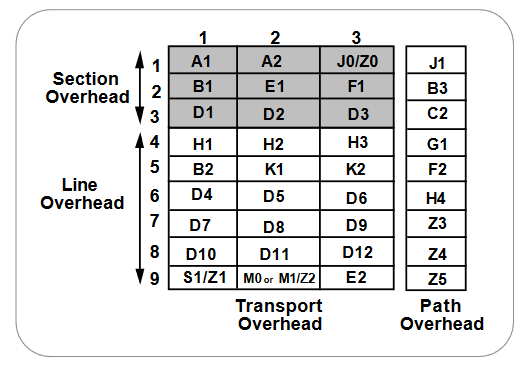
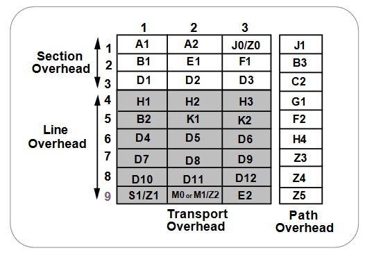
Table 4. Line Overhead
| Byte | Description | |
| H1, H2 | STS Payload Pointer (H1 and H2) – Two bytes are allocated to a pointer that indicates the offset in bytes between the pointer and the first byte of the STS SPE. The pointer bytes are used in all STS-1s within an STS-N to align the STS-1 Transport Overhead in the STS-N, and to perform frequency justification. These bytes are also used to indicate concatenation, and to detect STS Path Alarm Indication Signals (AIS-P). | |
| H3 | Pointer Action Byte (H3) – The pointer action byte is allocated for SPE frequency justification purposes. The H3 byte is used in all STS-1s within an STS-N to carry the extra SPE byte in the event of a negative pointer adjustment. The value contained in this byte when it’s not used to carry the SPE byte is undefined. | |
| B2 | Line bit interleaved parity code (BIP-8) byte – This parity code byte is used to determine if a transmission error has occurred over a line. It’s even parity, and is calculated over all bits of the Line Overhead and STS-1 SPE of the previous STS-1 frame before scrambling. The value is placed in the B2 byte of the Line Overhead before scrambling. This byte is provided in all STS-1 signals in an STS-N signal. | |
| K1 and K2 | Automatic Protection Switching (APS channel) bytes – These two bytes are used for Protection Signaling between Line Terminating entities for bidirectional automatic protection switching and for detecting alarm indication signal (AIS-L) and Remote Defect Indication (RDI) signals. | |
| K1 Byte Bits 1-4 Type of request 1111 Lock out of Protection 1110 Forced Switch 1101 SF – High Priority 1100 SF – Low Priority 1011 SD – High Priority 1010 SD – Low Priority 1001 (not used) 1000 Manual Switch 0111 (not used) 0110 Wait-to-Restore 0101 (not used) 0100 Exercise 0011 (not used) 0010 Reverse Request 0001 Do Not Revert 0000 No Request |
K2 Byte Bits 1-4 Selects channel number Bit 5 Indication of architecture 0 1+1 1 1:n Bit 6-8 Mode of operation 111 AIS-L 110 RDI-L 101 Provisioned mode is bidirectional 100 Provisioned mode is unidirectional 011 Future use 010 Future use 001 Future use 000 Future use |
|
| Bits 5-8 Indicate the number of the channel requested | ||
| D4 to D12 | Line Data Communications Channel (DCC) bytes – These nine bytes form a 576 kb/s message channel from a central location for OAM&P information (alarms, control, maintenance, remote provisioning, monitoring, administration, and other communication needs) between line entities. A protocol analyzer is required to access the Line-DCC information. | |
| S1 | Synchronization Status (S1) – The S1 byte is located in the first STS-1 of an STS-N, and bits 5 through 8 of that byte are allocated to convey the synchronization status of the network element. | |
| Z1 | Growth (Z1) – The Z1 byte is located in the second through Nth STS-1s of an STS-N (3≤N≤48), and is allocated for future growth. Note that an OC-1 or STS-1 electrical signal does not contain a Z1 byte. | |
| M0 | STS-1 REI-L (M0) – The M0 byte is only defined for STS-1 in an OC-1 or STS-1 electrical signal. Bits 5 through 8 are allocated for a Line Remote Error Indication function (REI-L – formerly referred to as Line FEBE), which conveys the error count detected by an LTE (using the Line BIP-8 code) back to its peer LTE. | |
| M1 | STS-N REI-L (M1) – The M1 byte is located in the third STS-1 (in order of appearance in the byte-interleaved STS-N electrical or OC-N signal) in an STS-N (N≥3), and is used for a REI-L function. | |
| Z2 | Growth (Z2) – The Z2 byte is located in the first and second STS-1s of an STS-3, and the first, second, and fourth through Nth STS-1s of an STS-N (12≤N≤48). These bytes are allocated for future growth. Note that an OC-1 or STS-1 electrical signal does not contain a Z2 byte. | |
| E2 | Orderwire byte – This orderwire byte provides a 64 kb/s channel between line entities for an express orderwire. It’s a voice channel for use by technicians and will be ignored as it passes through the regenerators. | |
STS Path Overhead
STS Path Overhead (STS POH) contains nine evenly distributed Path Overhead bytes per 125 microseconds starting at the first byte of the STS SPE. STS POH provides for communication between the point of creation of an STS SPE and its point of disassembly. This overhead supports functions such as:
- Performance monitoring of the STS SPE
- Signal label (the content of the STS SPE, including status of mapped payloads)
- Path status
- Path trace
The Path Overhead is found in Rows 1 to 9 of the first column of the STS-1 SPE (see Figure 9). Table 5 describes Path Overhead byte-by-byte.
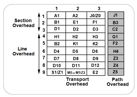
Table 5. Sect ion Overhead
| Byte | Description | ||
| J1 | STS path trace byte – This user-programmable byte repetitively transmits a 64-byte, or 16-byte E.164 format string. This allows the receiving terminal in a path to verify its continued connection to the intended transmitting terminal. | ||
| B3 | STS Path Bit Interleaved Parity code (Path BIP-8) byte – This is a parity code (even), used to determine if a transmission error has occurred over a path. Its value is calculated over all the bits of the previous synchronous payload envelope (SPE) before scrambling and placed in the B3 byte of the current frame. | ||
| C2 | STS Path signal label byte – This byte is used to indicate the content of the STS SPE, including the status of the mapped payloads. | ||
| Bits 1-4 0000 0000 0000 0000 0000 0001 0001 0001 0001 |
Bits 5-8 0000 0001 0010 0011 0100 0010 0011 0100 0101 |
Status Unequipped Equipped VT-structured STS-1 SPE Locked VT mode Asynchronous mapping for DS3 Asynchronous mapping for DS4NA Mapping for ATM Mapping for DQDB Asynchronous mapping for FDDI |
|
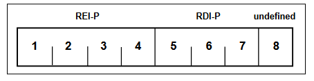
| G1 | Path status byte – This byte is used to convey the path terminating status and performance back to the originating path terminating equipment. Therefore, the duplex path in its entirety can be monitored from either end, or from any point along the path. Bits 1 through 4 are allocated for an STS Path REI function (REI-P – formerly referred to as STS Path FEBE). Bits 5, 6, and 7 of the G1 byte are allocated for an STS Path RDI (RDI-P) signal. Bit 8 of the G1 byte is currently undefined. | ||
 |
|||
| Bits `1-4 | STS Path REI function | ||
| Bits 5-7 | STS Path RDI function (Trigger & Interpretation) | ||
| 111 110 101 100 011 010 001 000 |
AIS-P, LOP-P UNEQ-P, TIM-P AIS-P, LOP-P AIS-P, LOP-P No defects PLM-P, LCD-P No defects No defects |
Remote defect Remote connectivity defect Remote server defect Remote defect No remote defect Remote payload defect No remote defect No remote defect |
|
| Bit 8 | Undefined | ||
| F2 | Path user channel byte – This byte is used for user communication between path elements. | ||
| H4 | Virtual Tributary (VT) multiframe indicator byte – This byte provides a generalized multiframe indicator for payload containers. At present, it’s used only for tributary unit structured payloads. | ||
NOTE: The Path Overhead Portion of the SPE remains with the payload until it’s demultiplexed.
VT Path Overhead
VT Path Overhead (VT POH) contains four evenly distributed Path Overhead bytes per VT SPE starting at the first byte of the VT SPE. VT POH provides communication between the point of creation of an VT SPE and its point of disassembly.
Four bytes (V5, J2, Z6, and Z7) are allocated for VT POH. The first byte of a VT SPE (i.e., the byte in the location pointed to by the VT Payload Pointer) is the V5 byte, while the J2, Z6, and Z7 bytes occupy the corresponding locations in the subsequent 125 microsecond frames of the VT Superframe.
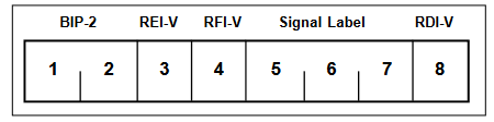
The V5 byte provides the same functions for VT paths that the B3, C2,and G1 bytes provide for STS paths; namely error checking, signal label,and path status. The bit assignments for the V5 byte are described in Table 6.
Table 6. VT Path Overhead
| Byte | Description | |
| V5 | VT path overhead byte. | |
 |
||
| Bits 1-2 Bit 3 Bit 4 Bits 5-7 000 001 010 011 100 101 110 111 Bit 8 |
Allocated for error performance monitoring. Allocated for a VT Path REI function (REI-V – formerly referred to as VT Path FEBE) to convey the VT Path terminating performance back to an originating VT PTE. Allocated for a VT Path Remote Failure Indication (RFI-V) in the byte-synchronous DS1 mapping. Allocated for a VT Path Signal Label to indicate the content of the VT SPE. Unequipped Equipped – non-specific payload Asynchronous mapping Bit synchronous mapping (no longer valid for DS1) Byte synchronous mapping Unassigned Unassigned Unassigned Allocated for a VT Path Remote Defect Indication (RDI-V) signal |
|
| J2 | VT Path trace identifier – This byte is used to support the end-to-end monitoring of a path. | |
| Z6 | The Z6 byte is known as N2 in the SDH standard and is allocated to provide a Lower-Order Tandem Connection Monitoring (LO-TCM) function. | |
| Z7 | The Z7 byte is known as K4 in the SDH standard. Bits 1-4 are allocated for APS signaling for protection at the Lower-Order path level. Bits 5-7 are used in combination with V5 bit 8 for ERDI-V. Bit 8 is reserved for future use and has no defined value. | |
SONET Alarm Structure
The SONET frame structure has been designed to contain a large amount of overhead information. The overhead information provides a variety of management and other functions such as:
- Error performance monitoring
- Pointer adjustment information
- Path status
- Path trace
- Section trace
- Remote defect, error, and failure indications
- Signal labels
- New data flag indications
- Data communications channels (DCC)
- Automatic Protection Switching (APS) control
- Orderwire
- Synchronization status message
Much of this overhead information is involved with alarm and in-service monitoring of the particular SONET sections.
SONET alarms are defined as follows:
Anomaly – The smallest discrepancy which can be observed between the actual and desired characteristics of an item. The occurrence of a single anomaly does not constitute an interruption in the ability to perform a required function.
Defect – The density of anomalies has reached a level where the ability to perform a required function has been interrupted. Defects are used as input for performance monitoring, the control of consequent actions,and the determination of fault cause.
Failure – The inability of a function to perform a required action persisted beyond the maximum time allocated.
Table 7 describes SONET alarm anomalies, defects, and failures.
Table 7. Anomalies, Defects, and Failures
| Abbreviation | Description | Criteria |
| LOS | Loss of Signal | LOS is raised when the synchronous signal (STS-N) level drops below the threshold at which a BER of 1 in 103 is predicted.It could be due to a cut cable, excessive attenuation of the signal, or equipment fault. The LOS state clears when two consecutive framing patterns are received and no new LOS conditions detected. |
| OOF | Out of Frame Alignment | OOF state occurs when four or five consecutive SONET frames are received with invalid (errored) framing patterns (A1 and A2 bytes). The maximum time to detect OOF is 625 microseconds. OOF state clears when two consecutive SONET frames are received with valid framing patterns. |
| LOF | Loss of Frame Alignment | LOF state occurs when the OOF state exists for a specified time in milliseconds. The LOF state clears when an in-frame condition exists continuously for a specified time in milliseconds. |
| LOP | Loss of Pointer | LOP state occurs when N consecutive invalid pointers are received or “N” consecutive New Data Flags (NDF) are received (other than in a concatenation indicator), where N = 8, 9, or 10. LOP state is cleared when three equal valid pointers or three consecutive AIS indications are received.LOP can also be identified as:
|
| AIS | Alarm Indication Signal | The AIS is an all-ONES characteristic or adapted information signal. It’s generated to replace the normal traffic signal when it contains a defect condition in order to prevent consequential downstream failures being declared or alarms being raised.AIS can also be identified as:
|
| REI | Remote Error Indication | An indication returned to a transmitting node (source) that an errored block has been detected at the receiving node (sink).This indication was formerly known as Far End Block Error (FEBE).REI can also be identified as:
|
| RDI | Remote Defect Indication | A signal returned to the transmitting Terminating Equipment upon detecting a Loss of Signal, Loss of Frame, or AIS defect.RDI was previously known as FERF.RDI can also be identified as:
|
| RFI | Remote Failure Indication | A failure is a defect that persists beyond the maximum time allocated to the transmission system protection mechanisms.When this situation occurs, an RFI is sent to the far end and will initiate a protection switch if this function has been enabled.RFI can also be identified as:
|
| B1 error | B1 error | Parity errors evaluated by byte B1 (BIP-8) of an STS-N are monitored. If any of the eight parity checks fail, the corresponding block is assumed to be in error. |
| B2 error | B2 error | Parity errors evaluated by byte B2 (BIP-24 x N) of an STS-N are monitored. If any of the N x 24 parity checks fail, the corresponding block is assumed to be in error. |
| B3 error | B3 error | Parity errors evaluated by byte B3 (BIP-8) of a VT-N (N = 3, 4) are monitored. If any of the eight parity checks fail, the corresponding block is assumed to be in error. |
| BIP-2 error | BIP-2 error | Parity errors contained in bits 1 and 2 (BIP-2: Bit Interleaved Parity-2) of byte V5 of an VT-M (M = 11, 12, 2) is monitored. If any of the two parity checks fail, the corresponding block is assumed to be in error. |
| LSS | Loss of Sequence Synchronization | Bit error measurements using pseudo-random sequences can only be performed if the reference sequence produced on the receiving side of the test set-up is correctly synchronized to the sequence coming from the object under test. In order to achieve compatible measurement results, it’s necessary that the sequence synchronization characteristics are specified. Sequence synchronization is considered to be lost and resynchronization shall be started if:
|
Pointers
SONET uses a concept called “pointers” to compensate for frequency and phase variations. Pointers allow the transparent transport of synchronous payload envelopes (either STS or VT) across plesiochronous boundaries (that is, between nodes with separate network clocks having almost the same timing). The use of pointers avoids the delays and loss of data associated with the use of large (125-microsecond frame) slip buffers for synchronization.
Pointers provide a simple means of dynamically and flexibly phasealigning STS and VT payloads, thereby permitting ease of dropping,inserting, and cross-connecting these payloads in the network.Transmission signal wander and jitter can also be readily minimized with pointers.
Figure 10 shows an STS-1 pointer (H1 and H2 bytes) which allows the SPE to be separated from the transport overhead. The pointer is simply an offset value that points to the byte where the SPE begins. The diagram depicts the typical case of the SPE overlapping onto two STS-1 frames. If there are any frequency or phase variations between the STS-1 frame and its SPE, the pointer value will be increased or decreased accordingly to maintain synchronization.
VT Mappings
There are several options for how payloads are actually mapped into the VT. Locked-mode VTs bypass the pointers with a fixed byte-oriented mapping of limited flexibility. Floating mode mappings use the pointers to allow the payload to float within the VT payload. There are three different floating mode mappings – asynchronous, bit-synchronous, and byte-synchronous.
Concatenated Payloads
For future services, the STS-1 may not have enough capacity to carry some services. SONET offers the flexibility of concatenating STS-1s to provide the necessary bandwidth. Consult the Glossary for an explanation of concatenation. STS-1s can be concatenated up to STS-3c. Beyond STS-3, concatenation is done in multiples of STS-3c. Virtual tributaries can be concatenated up to VT-6 in increments of VT-1.5, VT-2, or VT-6.
Payload Pointers
When there’s a difference in phase or frequency, the pointer value is adjusted. To accomplish this, a process known as byte stuffing is used. In other words, the SPE payload pointer indicates where in the container capacity a VT starts, and the byte stuffing process allows dynamic alignment of the SPE in case it slips in time.
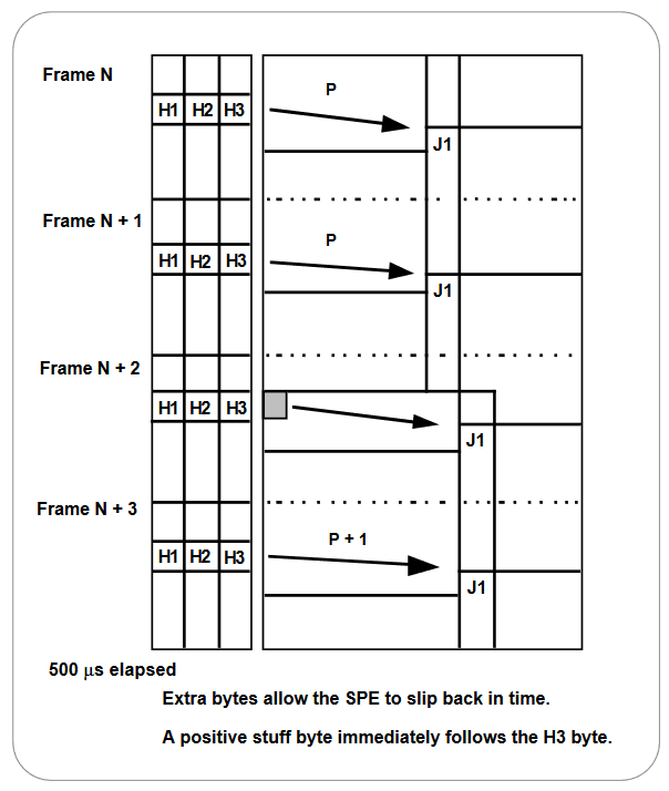
Positive Stuffing
When the frame rate of the SPE is too slow in relation to the rate of the STS-1, bits 7, 9, 11, 13, and 15 of the pointer word are inverted in one frame, thus allowing 5-bit majority voting at the receiver. (These bits are known as the I-bits or Increment bits.) Periodically, when the SPE is about one byte off, these bits are inverted, indicating that positive stuffing must occur. An additional byte is stuffed in, allowing the alignment of the container to slip back in time. This is known as positive stuffing, and the stuff byte is made up of non-information bits. The actual positive stuff byte immediately follows the H3 byte (that is, the stuff byte is within the SPE portion). The pointer is incremented by one in the next frame, and the subsequent pointers contain the new value. Simply put, if the SPE frame is traveling more slowly than the STS-1 frame, every now and then “stuffing” an extra byte in the flow gives the SPE a onebyte delay. See Figure 11.
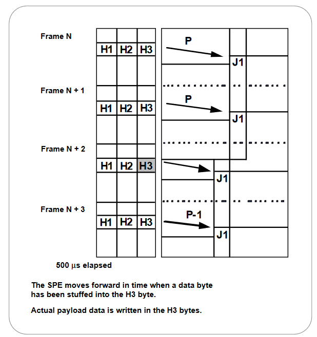
Negative Stuffing
Conversely, when the frame rate of the SPE frame is too fast in relation to the rate of the STS-1 frame, bits 8, 10, 12, 14, and 16 of the pointer word are inverted, thus allowing 5-bit majority voting at the receiver. (These bits are known as the D-bits, or Decrement bits.) Periodically, when the SPE frame is about one byte off, these bits are inverted, indicating that negative stuffing must occur. Because the alignment of the container advances in time, the envelope capacity must be moved forward. Thus, actual data is written in the H3 byte, the negative stuff opportunity (within the Overhead); this is known as negative stuffing.
The pointer is decremented by one in the next frame, and the subsequent pointers contain the new value. Simply put, if the SPE frame is traveling more quickly than the STS-1 frame, every now and then pulling an extra byte from the flow and stuffing it into the Overhead capacity (the H3 byte) gives the SPE a one-byte advance. In either case, there must be at least three frames in which the pointer remains constant before another stuffing operation (and therefore a pointer value change) can occur. See Figure 12.
Virtual Tributaries
In addition to the STS-1 base format, SONET also defines synchronous formats at sub-STS-1 levels. The STS-1 payload may be subdivided into virtual tributaries, which are synchronous signals used to transport lower-speed transmissions.The sizes of VTs are shown in Table 8.
In order to accommodate mixes of different VT types within an STS-1 SPE, the VTs are grouped together. An STS-1 SPE that is carrying Virtual Tributaries is divided into seven VT Groups, with each VT Group using 12 columns of the STS-1 SPE; note that the number of columns in each of the different VT types – 3, 4, 6, and 12 – are all factors of 12. Each VT Group can contain only one size (type) of Virtual Tributary, but within an STS-1 SPE, there can be a mix of the different VT Groups.
For example, an STS-1 SPE may contain four VT1.5 groups and three VT6 groups, for a total of seven VT Groups. Thus, an SPE can carry a mix of any of the seven groups. The groups have no overhead or pointers;they’re just a way of organizing the different VTs within an STS-1 SPE.
Since each of the VT Groups is allocated 12 columns of the Synchronous Payload Envelope, a VT Group would contain one of the following combinations:
- Four VT1.5s (with 3 columns per VT1.5)
- Three VT2s (with 4 columns per VT2)
- Two VT3s (with 6 columns per VT3)
- One VT6 (with 12 columns per VT6)
The 12 columns in a VT Group are not consecutive within the SPE; they’re interleaved column by column with respect to the other VT groups. As well, column 1 is used for the Path Overhead; the two columns of “fixed stuff” are assigned to columns 30 and 59.
The first VT Group, called Group 1, is found in every seventh column, starting with column 2, and skipping columns 30 and 59. That is, the 12 columns for VT Group 1 are columns 2, 9, 16, 23, 31, 38, 45, 52, 60, 67, 74, and 81.
Table 8. Virtua l Tr ibutar ies (VT)
| VT Type | Bit Rate | Size of VT |
| VT1.5 | 1.728 Mb/s | 9 rows, 3 column |
| VT2 | 2.304 Mb/s | 9 rows, 4 columns |
| VT3 | 3.456 Mb/s | 9 rows, 6 columns |
| VT6 | 6.912 Mb/s | 9 rows, 12 columns |
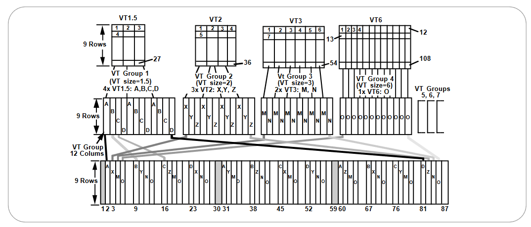
Just as the VT Group columns are not placed in consecutive columns in an STS-1 SPE, the Virtual Tributary columns within a group are not placed in consecutive columns within that group. The columns of the individual VTs within the VT Group are interleaved as well. See Figure 13.
The VT structure is designed for transport and switching of sub-STS-1 rate payloads. There are four sizes of VTs: VT1.5 (1.728 Mb/s), VT2 (2.304 Mb/s), VT3 (3.456 Mb/s), and VT6 (6.912 Mb/s). In the 87 column by 9 row structure of the STS-1 SPE, these VTs occupy columns 3, 4, 6, and 12, respectively.
To accommodate a mix of VT sizes efficiently, the VT structured STS-1 SPE is divided into seven VT groups. Each VT group occupies 12 columns of the 87 column STS-1 SPE, and may contain 4 VT1.5s, 3 VT2s,2 VT3s, or 1 VT6. A VT group can contain only one size of VTs; however,a different VT size is allowed for each VT group in an STS-1 SPE. See Figure 14.
STS-1 VT1.5 SPE Columns
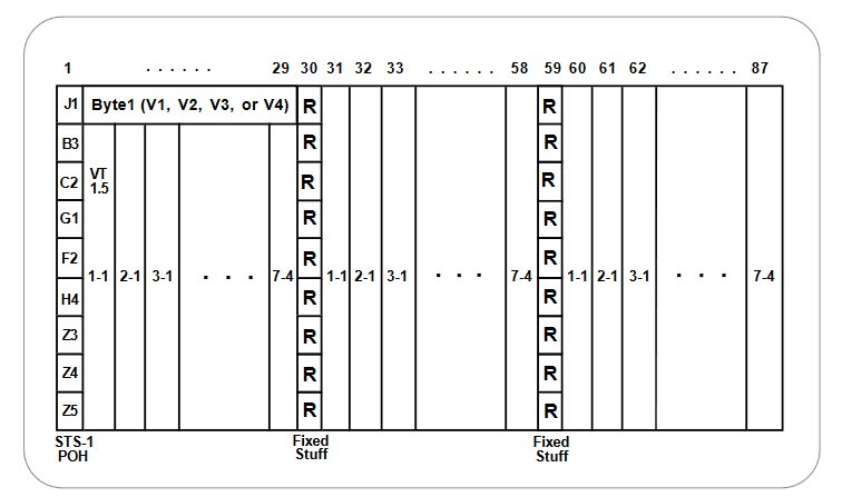
One of the benefits of SONET is that it can carry large payloads (above 50 Mb/s). However, the existing digital hierarchy can be accommodated as well, thus protecting investments in current equipment. To achieve this capacity, the STS Synchronous Payload Envelope (SPE) can be sub-divided into smaller components or structures, known as Virtual Tributaries (VT) for the purpose of transporting and switching payloads smaller than the STS-1 rate. All services below the DS3 rate are transported in the VT structure. Figure 15 shows the VT1.5 structured STS-1 SPE. Table 9 matches up the VT1.5 locations and the STS-1 SPE column numbers, per the Bellcore GR-253-CORE standard.
DS1 Visibility
Because the multiplexing is synchronous, the low-speed tributaries (input signals) can be multiplexed together but are still visible at higher rates. An individual VT containing a DS1 can be extracted without demultiplexing the entire STS-1. This improved accessibility improves switching and grooming at VT or STS levels.
In an asynchronous DS3 frame, the DS1s have gone through two levels of multiplexing (DS1 to DS2; DS2 to DS3) which include the addition of stuffing and framing bits. The DS1 signals are mixed somewhere in the information-bit fields and cannot be easily identified without completely demultiplexing the entire frame.
Different synchronizing techniques are used for multiplexing. In existing asynchronous systems, the timing for each fiber-optic transmission system terminal is not locked onto a common clock. Therefore, large frequency variations can occur. “Bit stuffing” is a technique used to synchronize the various low-speed signals to a common rate before multiplexing.
Table 9. VT1.5 Locations matched to the STS-1 SPE Column Numbers
| VT Group #, VT # | Column #s |
| 1,1 | 2,31,60 |
| 2,1 | 3,32,61 |
| 3,1 | 4,33,62 |
| 4,1 | 5,34,63 |
| 5,1 | 6,35,64 |
| 6,1 | 7,36,65 |
| 7,1 | 8,37,66 |
| 1,2 | 9,38,67 |
| 2,2 | 10,39,68 |
| 3,2 | 11,40,69 |
| 4,2 | 12,41,70 |
| 5,2 | 13,42,71 |
| 6,2 | 14,43,72 |
| 7,2 | 15,44,73 |
| 1,3 | 16,45,74 |
| 2,3 | 17,46,75 |
| 3,3 | 18,47,76 |
| 4,3 | 19,48,77 |
| 5,3 | 20,49,78 |
| 6,3 | 21,50,79 |
| 7,3 | 22,51,80 |
| 1,4 | 23,52,81 |
| 2,4 | 24,53,82 |
| 3,4 | 25,54,83 |
| 4,4 | 26,55,84 |
| 5,4 | 27,56,85 |
| 6,4 | 28,57,86 |
| 7,4 | 29,58,87 |
Column 1 = STS-1 POH
30 = Fixed Stuff
59 = Fixed Stuff
VT Superframe and Envelope Capacity
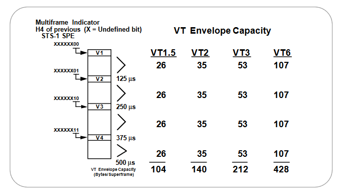
In addition to the division of VTs into VT groups, a 500-microsecond structure called a VT Superframe is defined for each VT. The VT Superframe contains the V1 and V2 bytes (the VT Payload Pointer), and the VT Envelope Capacity, which in turn contains the VT SPE. The VT Envelope Capacity, and therefore the size of the VT SPE, is different for each VT size. V1 is the first byte in the VT Superframe, while V2 through V4 appear as the first bytes in the following frames of the VT Superframe, regardless of the VT size. See Figure 16.
VT SPE and Payload Capacity
Four consecutive 125-microsecond frames of the VT-structured STS-1 SPE are organized into a 500-microsecond superframe, the phase of which is indicated by the H4 (Indicator) byte in the STS POH.
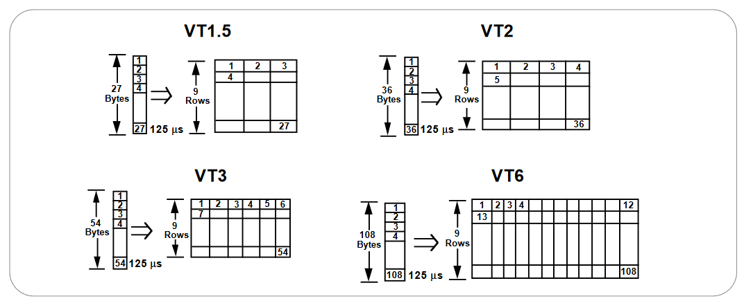
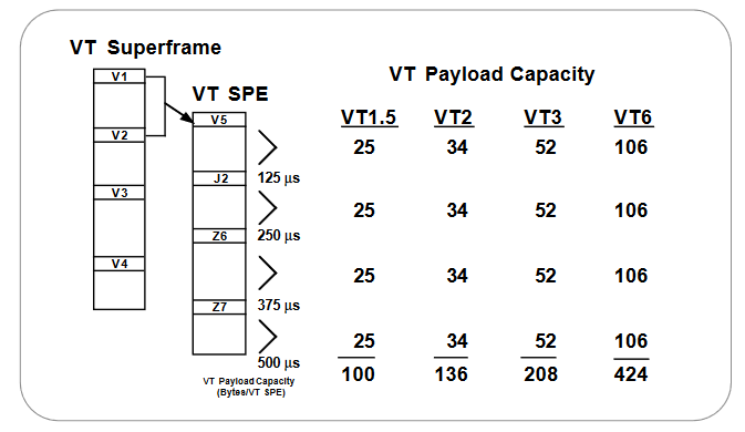
The VT Payload Pointer provides flexible and dynamic alignment of the VT SPE within the VT Envelope Capacity, independent of other VT SPEs. Figure 17 illustrates the VT SPEs corresponding to the four VT sizes. Each VT SPE contains four bytes of VT POH (V5, J2, Z6, and Z7),and the remaining bytes constitute the VT Payload Capacity, which is different for each VT.
SONET Multiplexing
The multiplexing principles of SONET are:
- Mapping – A process used when tributaries are adapted into Virtual Tributaries (VTs) by adding justification bits and Path Overhead (POH) information.
- Aligning – This process takes place when a pointer is included in the STS Path or VT Path Overhead, to allow the first byte of the Virtual Tributary to be located.
- Multiplexing – This process is used when multiple lower-order path-layer signals are adapted into a higher-order path signal, or when the higherorder path signals are adapted into the Line Overhead.
- Stuffing – SONET has the ability to handle various input tributary rates from asynchronous signals. As the tributary signals are multiplexed and aligned, some spare capacity has been designed into the SONET frame to provide enough space for all these various tributary rates. Therefore, at certain points in the multiplexing hierarchy this space capacity is filled with “fixed stuffing” bits that carry no information, but are required to fill up the particular frame.
One of the benefits of SONET is that it can carry large payloads (above 50 Mb/s). However, the existing digital hierarchy signals can be accommodated as well, thus protecting investments in current equipment.
To achieve this capability, the STS Synchronous Payload Envelope can be sub-divided into smaller components or structures, known as Virtual Tributaries (VTs), for the purpose of transporting and switching payloads smaller than the STS-1 rate. All services below DS3 rate are transported in the VT structure.
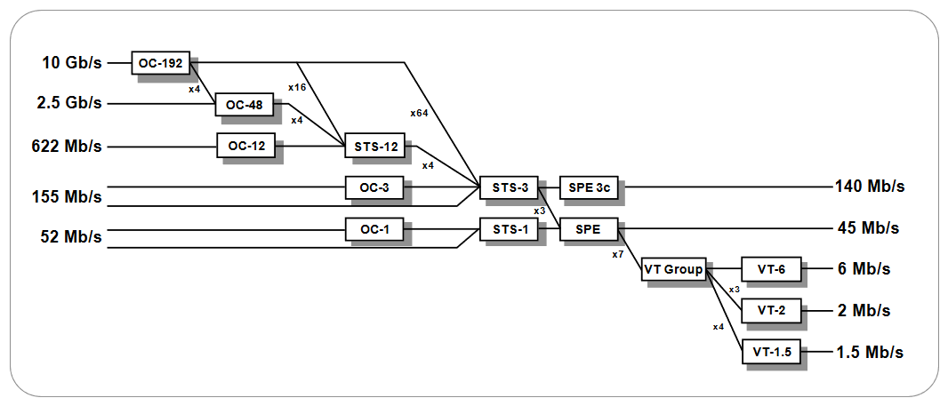
Figure 18 illustrates the basic multiplexing structure of SONET. Any type of service, ranging from voice to high-speed data and video, can be accepted by various types of service adapters. A service adapter maps the signal into the payload envelope of the STS-1 or virtual tributary (VT). New services and signals can be transported by adding new service adapters at the edge of the SONET network.
Except for concatenated signals, all inputs are eventually converted to a base format of a synchronous STS-1 signal (51.84 Mb/s or higher). Lower speed inputs such as DS1s are first bit- or byte-multiplexed into virtual tributaries. Several synchronous STS-1s are then multiplexed together in either a single- or two-stage process to form an electrical STS-N signal (N = 1 or more).
STS multiplexing is performed at the Byte Interleave Synchronous Multiplexer. Basically, the bytes are interleaved together in a format such that the low-speed signals are visible. No additional signal processing occurs except a direct conversion from electrical to optical to form an OC-N signal.
SONET Network Elements
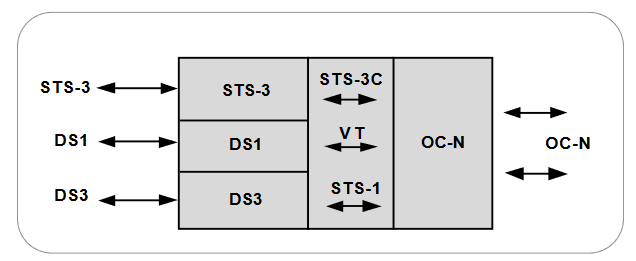
Terminal Multiplexer
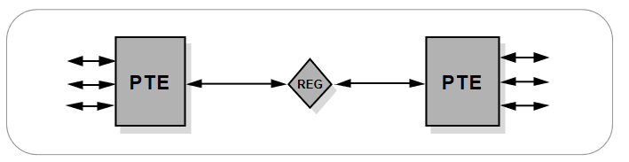
The path terminating element (PTE), an entry level path terminating terminal multiplexer, acts as a concentrator of DS1s as well as other tributary signals. Its simplest deployment would involve two terminal multiplexers linked by fiber with or without a regenerator in the link. This implementation represents the simplest SONET link (a Section, Line, and Path all in one link). See Figure 19.
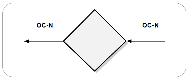
Regenerator
A regenerator is needed when, due to the long distance between multiplexers, the signal level in the fiber becomes too low.
The regenerator clocks itself off of the received signal and replaces the Section Overhead bytes before re-transmitting the signal. The Line Overhead, payload, and Path Overhead are not altered. See Figure 20.
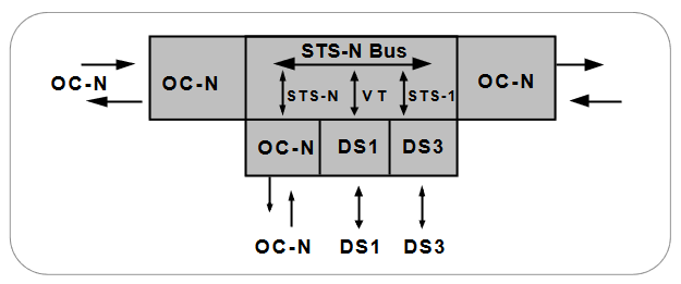
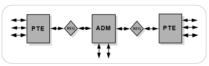
Add/Drop Multiplexer (ADM)
Although network elements (NEs) are compatible at the OC-N level, they may differ in features from vendor to vendor. SONET does not restrict manufacturers to providing a single type of product, nor require them to provide all types. For example, one vendor might offer an add/drop multiplexer with access at DS1 only, whereas another might offer simultaneous access at DS1 and DS3 rates. See Figure 21.
A single-stage multiplexer/demultiplexer can multiplex various inputs into an OC-N signal. At an add/drop site, only those signals that need to be accessed are dropped or inserted. The remaining traffic continues through the network element without requiring special pass-through units or other signal processing.
In rural applications, an ADM can be deployed at a terminal site or any intermediate location for consolidating traffic from widely separated locations. Several ADMs can also be configured as a survivable ring.
SONET enables drop and repeat (also known as drop and continue) – a key capability in both telephony and cable TV applications.With drop and repeat, a signal terminates at one node, is duplicated (repeated), and is then sent to the next and subsequent nodes.
In ring-survivability applications, drop and repeat provides alternate routing for traffic passing through interconnecting rings in a “matched-nodes” configuration. If the connection cannot be made through one of the nodes, the signal is repeated and passed along an alternate route to the destination node.
In multi-node distribution applications, one transport channel can efficiently carry traffic between multiple distribution nodes. When transporting video, for example, each programming channel is delivered (dropped) at the node and repeated for delivery to the next and subsequent nodes. Not all bandwidth (program channels) need be terminated at all the nodes. Channels not terminating at a node can be passed through without physical intervention to other nodes. The add-drop multiplexer provides interfaces between the different network signals and SONET signals.
Single-stage multiplexing can multiplex/demultiplex one or more Tributary (DS1) signals into/from an STS-N signal. It can be used in terminal sites, intermediate (add-drop) sites, or hub configurations. At an add-drop site, it can drop lower-rate signals to be transported on different facilities, or it can add lower-rate signals into the higher-rate STS-N signal. The rest of the traffic simply continues straight through.
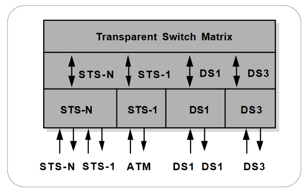
Wideband Digital Cross-Connects
A SONET cross-connect accepts various optical carrier rates, accesses the STS-1 signals, and switches at this level. It’s ideally used at a SONET hub. One major difference between a cross-connect and an adddrop multiplexer is that a cross-connect may be used to interconnect a much larger number of STS-1s. The broadband cross-connect can be used for grooming (consolidating or segregating) of STS-1s or for broadband traffic management. For example, it may be used to segregate high-bandwidth from low-bandwidth traffic and send them separately to the high-bandwidth (e.g., video) switch and a low-bandwidth (voice) switch. It’s the synchronous equivalent of a DS3 digital cross-connect and supports hubbed network architectures.
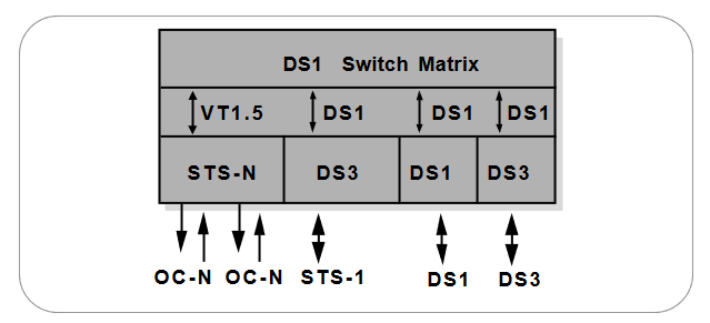
This type is similar to the broadband cross-connect except that the switching is done at VT levels (similar to DS1/DS2 levels). It is similar to a DS3/1 cross-connect because it accepts DS1s, DS3s, and is equipped with optical interfaces to accept optical carrier signals. It’s suitable for DS1 level grooming applications at hub locations. One major advantage of wideband digital cross-connects is that less demultiplexing and multiplexing is required because only the required tributaries are accessed and switched.
The Wideband Digital Cross-Connect (W-DCS) is a digital cross-connect that terminates SONET and DS3 signals, as well as having the basic functionality of VT and DS1-level cross-connections. It’s the SONET equivalent to the DS3/DS1 digital cross-connect, and accepts optical OC-N signals as well as STS-1s, DS1s and DS3s.
In a Wideband Digital Cross-Connect, the switching is done at the VT level (i.e., it cross-connects the constituent VTs between STS-N terminations).
Because SONET is synchronous, the low-speed tributaries are visible and accessible within the STS-1 signal. Therefore, the required tributaries can be accessed and switched without demultiplexing, which isn’t possible with existing digital cross-connects. As well, the W-DCS cross-connects the constituent DS1s between DS3 terminations, and between DS3 and DS1 terminations.
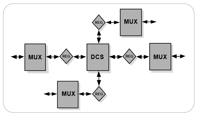
The features of the W-DCS make it useful in several applications.Because it can automatically cross-connect VTs and DS1s, the W-DCS can be used as a network management system. This capability, in turn,makes the W-DCS ideal for grooming at a hub location. See Figure 22.
Broadband Digital Cross-Connect
The Broadband Digital Cross-Connect interfaces various SONET signals and DS3s. It accesses the STS-1 signals, and switches at this level. It’s the synchronous equivalent of the DS3 digital cross-connect, except that the broadband digital cross-connect accepts optical signals and allows overhead to be maintained for integrated OAM&P (asynchronous systems prevent overhead from being passed from optical signal to signal).
The Broadband Digital Cross-Connect can make two-way cross-connections at the DS3, STS-1, and STS-Nc levels. It’s best used as a SONET hub, where it can be used for grooming STS-1s, for broadband restoration purposes, or for routing traffic. See Figure 23.
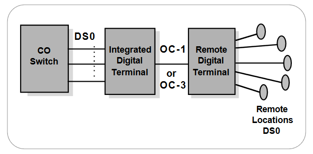
Digital Loop Carrier
The Digital Loop Carrier (DLC) may be considered a concentrator of lowspeed services before they are brought into the local central office for distribution. If this concentration were not done, the number of subscribers (or lines) that a central office could serve would be limited by the number of lines served by the CO. The DLC itself is actually a system of multiplexers and switches designed to perform concentration from the remote terminals to the community dial office and, from there, to the central office.
Whereas a SONET multiplexer may be deployed at the customer premises, a DLC is intended for service in the central office or a controlled environment vault (CEV) that belongs to the carrier. Bellcore document TR-TSY-000303 describes a generic Integrated Digital Loop Carrier (IDLC), which consists of intelligent Remote Digital Terminals (RDTs) and digital switch elements called Integrated Digital Terminals (IDTs), which are connected by a digital line. The IDLCs are designed to more efficiently integrate DLC systems with existing digital switches. See Figure 24.
SONET Network Configurations
Point-to-Point
The SONET multiplexer, an entry level path terminating terminal multiplexer, acts as a concentrator of DS1s as well as other tributaries. Its simplest deployment involves two terminal multiplexers linked by fiber with or without a regenerator in the link. This implementation represents the simplest SONET configuration.
In this configuration (Figure 25), the SONET path and the Service path (DS1 or DS3 links end-to-end) are identical and this synchronous island can exist within an asynchronous network world. In the future, point-topoint service path connections will span across the whole network and will always originate and terminate in a multiplexer.
Hub Network
The hub network architecture accommodates unexpected growth and change more easily than simple point-to-point networks. A hub (Figure 27) concentrates traffic at a central site and allows easy reprovisioning of the circuits.
There are two possible implementations of this type of network:
- Using two or more ADMs, and a wideband cross-connect switch which allows cross-connecting the tributary services at the tributary level.
- Using a broadband digital cross-connect switch which allows cross-connecting at both the SONET level and the tributary level.
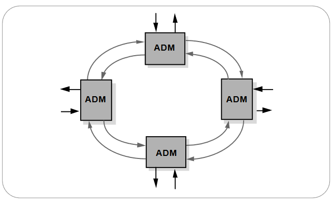
Ring Architecture
The SONET building block for a ring architecture is the ADM. Multiple ADMs can be put into a ring configuration for either bi-directional or uni-directional traffic (see Figure 28). The main advantage of the ring topology is its survivability; if a fiber cable is cut, the multiplexers have the intelligence to send the services affected via an alternate path through the ring without interruption.
The demand for survivable services, diverse routing of fiber facilities,flexibility to rearrange services to alternate serving nodes, as well as automatic restoration within seconds, have made rings a popular SONET topology
The Benefits of SONET
The transport network using SONET provides much more powerful networking capabilities than existing asynchronous systems. The key benefits provided by SONET are as follows.
Pointers, MUX/ DEMUX
As a result of SONET transmission, the network’s clocks are referenced to a highly stable reference point. Therefore, the need to align the data streams or synchronize clocks is unnecessary. Therefore, a lower rate signal such as DS1 is accessible, and demultiplexing is not needed to access the bitstreams. Also, the signals can be stacked together without bit stuffing.
For those situations in which reference frequencies may vary, SONET uses pointers to allow the streams to “float” within the payload envelope.Synchronous clocking is the key to pointers. It allows a very flexible allocation and alignment of the payload within the transmission envelope.
Reduced Back-to-Back Multiplexing
Separate M13 multiplexers (DS1 to DS3) and fiber optic transmission system terminals are used to multiplex a DS1 signal to a DS2, DS2 to DS3, and then DS3 to an optical line rate. The next stage is a mechanically integrated fiber/multiplex terminal.
In the existing asynchronous format, care must be taken when routing circuits in order to avoid multiplexing and demultiplexing too many times since electronics (and their associated capital cost) are required every time a DS1 signal is processed. With SONET, DS1s can be multiplexed directly to the OC-N rate. Because of synchronization, an entire optical signal doesn’t have to be demultiplexed, only the VT or STS signals that need to be accessed.
Optical Interconnect
Because of different optical formats among vendors’ asynchronous products, it’s not possible to optically connect one vendor’s fiber terminal to another. For example, one manufacturer may use 417 Mb/s line rate, another 565 Mb/s.
A major SONET value is that it allows mid-span meet with multi-vendor compatibility. Today’s SONET standards contain definitions for fiber-tofiber interfaces at the physical level. They determine the optical line rate, wavelength, power levels, pulse shapes, and coding. Current standards also fully define the frame structure, overhead, and payload mappings.Enhancements are being developed to define the messages in the overhead channels to provide increased OAM&P functionality.
SONET allows optical interconnection between network providers regardless of who makes the equipment. The network provider can purchase one vendor’s equipment and conveniently interface with other vendors’ SONET equipment at either the different carrier locations or customer premises sites. Users may now obtain the OC-N equipment of their choice and meet with their network provider of choice at that OC-N level.
Multipoint Configurations
The difference between point-to-point and multipoint systems was shown previously in Figures 25 and 26. Most existing asynchronous systems are only suitable for point-to-point, whereas SONET supports a multipoint or hub configuration.
A hub is an intermediate site from which traffic is distributed to three or more spurs. The hub allows the four nodes or sites to communicate as a single network instead of three separate systems. Hubbing reduces requirements for back-to-back multiplexing and demultiplexing, and helps realize the benefits of traffic grooming.
Network providers no longer need to own and maintain customer-located equipment. A multi-point implementation permits OC-N interconnects or mid-span meet, allowing network providers and their customers to optimize their shared use of the SONET infrastructure.
Convergence, ATM, IP, Video, and SONET
Convergence is the trend toward delivery of audio, data, images, and video through diverse transmission and switching systems that supply high-speed transportation over any medium to any location. Tektronix is pursuing every opportunity to lead the market providing test and measurement equipment to markets that process or transmit audio,data, image, and video signals over high-speed networks.
With its modular, service-independent architecture, SONET provides vast capabilities in terms of service flexibility. Some broadband services use Asynchronous Transfer Mode (ATM) – a fast packet-switching technique using short, fixed-length packets called cells. Asynchronous Transfer Mode multiplexes the payload into cells that may be generated and routed as necessary. Because of the bandwidth capacity it offers, SONET is a logical carrier for ATM. Also, as local and wide area networks converge, Packet over SONET (PoS) technologies allow the transport of IP packets of SONET rates.
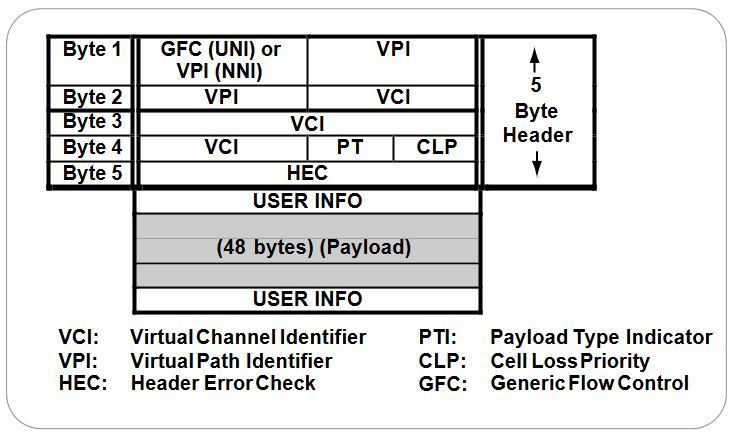
In principle, ATM is quite similar to other packet-switching techniques; however, the detail of ATM operation is somewhat different. Each ATM cell is made up of 53 octets, or bytes (see Figure 29). Of these, 48 octets make up the user-information field and five octets make up the header. The cell header identifies the “virtual path” to be used in routing the cell through the network. The virtual path defines the connections through which the cell is routed to reach its destination.
A Packet-based network is bandwidth-transparent, which allows handling of a dynamically variable mixture of services at different bandwidths. Packet networks also easily accommodate traffic of variable speeds. An example of an application that requires the benefits of variable-rate traffic is that of a video CODEC. The video signals can be packed within ATM or IP cells for transport.
Grooming
Grooming refers to either consolidating or segregating traffic to make more efficient use of the facilities. Consolidation means combining traffic from different locations onto one facility.
Segregation is the separation of traffic. With existing systems, the cumbersome technique of back-hauling might be used to reduce the expense of repeated multiplexing and demultiplexing.
Grooming eliminates inefficient techniques like back-hauling. It’s possible to groom traffic on asynchronous systems, however to do so requires expensive back-to-back configurations and manual DSX panels or electronic cross-connects. By contrast, a SONET system can segregate traffic at either an STS-1 or VT level to send it to the appropriate nodes.
Grooming can also provide segregation of services. For example, at an interconnect point, an incoming SONET line may contain different types of traffic, such as switched voice, data, or video. A SONET network can conveniently segregate the switched and non-switched traffic.
Reduced Cabling and Elimination of DSX Panels
Asynchronous systems are dominated by back-to-back terminals because the asynchronous fiber-optic transmission system architecture is inefficient for other than point-to-point networks. Excessive multiplexing and demultiplexing are used to transport a signal from one end to another, and many bays of DSX-1 cross-connect and DSX-3 panels are required to interconnect the systems. Associated expenses are the panel, bays, cabling, the labor installation, and the inconveniences of increased floor space and congested cable racks.
The corresponding SONET system allows a hub configuration, reducing the need for back-to-back terminals. Grooming is performed electronically so DSX panels are not used except when required to interface with existing asynchronous equipment.
Enhanced OAM&p
SONET allows integrated network OAM&P (also known as OA&M), in accordance with the philosophy of single-ended maintenance. In other words, one connection can reach all network elements (within a given architecture); separate links are not required for each network element. Remote provisioning provides centralized maintenance and reduced travel for maintenance personnel – which translates to expense savings.
Enhanced Performance Monitoring
Substantial overhead information is provided in SONET to allow quicker troubleshooting and detection of failures before they degrade to serious levels.
SDH Reference
Following development of the SONET standard by ANSI, the CCITT undertook to define a synchronization standard that would address interworking between the CCITT and ANSI transmission hierarchies. That effort culminated in 1989 with CCITT’s publication of the Synchronous Digital Hierarchy (SDH) standards. Synchronous Digital Hierarchy is a world standard, and as such, SONET can be considered a subset of SDH.
Transmission standards in the U.S., Canada, Korea, Taiwan, and Hong Kong (ANSI) and the rest of the world (ITU-T, formerly CCITT) evolved from different basic-rate signals in the non-synchronous hierarchy. ANSI Time Division Multiplexing (TDM) combines twenty four 64-kb channels (DS0s) into one 1.54-Mb/s DS1 signal. ITU-T TDM multiplexes thirty-two 64-kb channels (E0s) into one 2.048 Mb/s E-1 signal.
The issues between ITU-T and ANSI standards-makers involved how to efficiently accommodate both the 1.5-Mb/s and the 2-Mb/s nonsynchronous hierarchies in a single synchronization standard. The agreement reached specifies a basic transmission rate of 52 Mb/s for SONET and a basic rate of 155 Mb/s for SDH.
Synchronous and non-synchronous line rates and the relationships between each are shown in Tables 10 and 11.
Convergence of SONET and SDH Hierarchies
SONET and SDH converge at SONET’s 52-Mb/s base level, defined as STM-0 or “Synchronous Transport Module-0”. The base level for SDH is STM-1 which is equivalent to SONET’s STS-3 (3 x 51.84 Mb/s = 155.5 Mb/s). Higher SDH rates are STM-4 (622 Mb/s) and STM-16 (2.5 Gb/s). STM-64 (10 Gb/s) has also been defined.
Multiplexing is accomplished by combining – or interleaving – multiple lowerorder signals (1.5 Mb/s, 2 Mb/s, etc.) into higher-speed circuits (52 Mb/s, 155 Mb/s, etc.). By changing the SONET standard from bit-interleaving to byte-interleaving, it became possible for SDH to accommodate both transmission hierarchies.
Asynchronous and Synchronous Tributaries
SDH does away with a number of the lower multiplexing levels, allowing non-synchronous 2-Mb/s tributaries to be multiplexed to the STM-1 level in a single step. SDH recommendations define methods of subdividing the payload area of an STM-1 frame in various ways so that it can carry combinations of synchronous and asynchronous tributaries. Using this method, synchronous transmission systems can accommodate signals generated by equipment operating from various levels of the non-synchronous hierarchy.
Table 10. SONET/SDH Hierarchies
| SONET Signal | Bit Rate | SDH Signal | SONET Capacity | SDH Capacity |
| STS-1, OC-1 | 51.840 Mb/s | STM-0 | 28 DS1s or 1 DS3 | 21 E1s |
| STS-3, OC-3 | 155.520 Mb/s | STM-1 | 84 DS1s or 3 DS3s | 63 E1s or 1 E4 |
| STS-12, OC-12 | 622.080 Mb/s | STM-4 | 336 DS1s or 12 DS3s | 252 E1s or 4 E4s |
| STS-48, OC-48 | 2488.320 Mb/s | STM-16 | 1344 DS1s or 48 DS3s | 1008 E1s or 16 E4s |
| STS-192, OC-19 | 9953.280 Mb/s | STM-64 | 5376 DS1s or 192 DS3s | 4032 E1s or 64 E4s |
| STS-768, OC-768 | 39813.12 Mb/s | STM-256 | 21504 DS1s or 768 DS3s | 16128 E1s or 256 E4s |
NOTE: Although an SDH STM-1 has the same bit rate as the SONET STS-3, the two signals contain different frame structures.
STM = Synchronous Transport Module (ITU-T)
STS = Synchronous Transfer Signal (ANSI)
OC = Optical Carrier (ANSI)
Table 11. Non-Synchronous Hierarchies
| Signal | Bit Rate | Channels | Signal | Bit Rate | Channels |
| DS0 | 64 kb | 1 DS0 | 64-kb | 64 kb | 1 64-kb |
| DS1 | 1.544 Mb/s | 24 DS0s | E1 | 2.048 Mb/s | 1 E1 |
| DS2 | 6.312 Mb/s | 96 DS0s | E2 | 8.45 Mb/s | 4 E1s |
| DS3 | 44.7 Mb/s | 28 DS1s | E3 | 34 Mb/s | 16 E1s |
| not defined | E4 | 144 Mb/s | 64 E1s |
Find more valuable resources at TEK.COM
Copyright © Tektronix. All rights reserved. Tektronix products are covered by U.S. and foreign patents, issued and pending. Information in this publication supersedes that in all previously published material. Specification and price change privileges reserved. TEKTRONIX and TEK are registered trademarks of Tektronix, Inc. All other trade names referenced are the service marks, trademarks or registered trademarks of their respective companies.
8/01 2RW-11407-2