Introduction
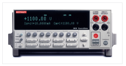
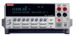
In 1996, Keithley Instruments launched the 2410 High Voltage SourceMeter® source measure unit (SMU) for performing current vs. voltage (IV) characterization on components such as high voltage semiconductor devices, transient suppression devices, circuit protection devices, connectors, relays, switches, and much more. The 2410 found its way into advanced research and development applications where new materials and devices were being innovated. The 2410 is a unique instrument, able to source up to 1100 V at 20 mA and provided the user with the ability to create IV sweeps directly from the front panel.
If you are not familiar with the SMU, the instrument provides precision voltage and current sourcing as well as measurement capabilities. The SMU instrument is both a highly stable DC power source and a true instrument-grade 6½-digit multimeter. The power source characteristics include low noise, precision, and readback while the multimeter provides high repeatability and low noise current and voltage measurements. The result is a compact, single-channel, DC parametric tester. In operation, these instruments can act as a voltage source, a current source, a voltage meter, a current meter, and an ohmmeter. The SMU offers four-quadrant operation. In the first and third quadrants they operate as a source, delivering power to a load. In the second and fourth quadrants they operate as a sink, dissipating power internally. Voltage, current, and resistance can be measured during source or sink operation.
By linking source and measurement circuitry in a single compact, half-rack unit, the SMU offers a variety of advantages over systems configured with separate source and measurement instruments, conserving precious “real estate” in the test rack or on the bench. For example, they minimize the time required for test station development, setup, and maintenance, while lowering the overall cost of system ownership. They simplify the test process itself by eliminating many of the complex synchronization and connection issues associated with using multiple instruments.
The 2410 SourceMeter
The 2410 SourceMeter was an industry workhorse when it was launched. Twenty-five years later, it continues to be used in labs and production floors around the world.
The 2410 enabled the user to create a number of sweep types to greatly accelerate testing with automation hooks, including Linear Staircase, Logarithmic Staircase, and Custom “List” Sweep. These sweep types could be programmed for singleevent or continuous operation. They are ideal for I/V, I/R, V/I,and V/R characterization.
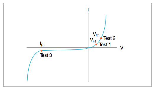
In addition, three sweep types, the 2410 also has a built-in test sequencer, which is referred to as a Source Memory List. The Source Memory List provides faster and easier testing by allowing the user to setup and execute up to 100 different tests that run without PC intervention. Each point of a Source Memory List can contain source settings, measurement settings, and pass/fail criteria. The pass/fail test can be executed as fast as 500 μs per point. For example, if you were testing something as simple as a Diode, an example test sequence might look like Figure 2.
| Test | Pass/Fail Test | If Passes Test | If Fails Test |
| Test 1 | Check VF1 at 100 mA against pass/fail limits | Go to Test 2 | 1. Bin part to bad bin 2. Transmit data to computer while handler is placing new part 3. Return to Test 1 |
| Test 2 | Check VF2 at 1 A againstpass/fail limits | Go to Test 3 | |
| Test 3 | Check leakage current at –500 V and test against pass/ fail limits | 1. Bin part to good bin 2. Transmit readings to computer while handler is placing new part 3. Return to Test 1 |
Figure 2: Example Diode Test Sequence
Unfortunately, like any good thing, the 2410’s life is coming to an end. You may have been a long-time user of the 2410 on your bench, or installed the SMU in your test systems, and want to continue to use it. The first thought that is probably going to cross your mind is what do I do if Keithley is no longer going to sell the 2410? How do I replace this great instrument? What does Keithley offer to help me replace the 2410? The answer is Keithley’s new 2470 High Voltage Graphical SourceMeter SMU.
The Keithley 2470 High Voltage Graphical SourceMeter
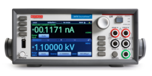
The Keithley 2470 High Voltage SourceMeter combines an innovative 5-inch touchscreen graphical user interface (GUI)to make testing intuitive and minimize the learning curve to help engineers and scientists learn faster, work smarter, and invent easier.
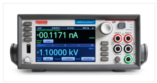
With its 1100 V and 10 fA measurement resolution capability, the 2470 is optimized for characterizing and testing high voltage, low leakage devices, materials, and modules, such as silicon carbide (SiC), gallium nitride (GaN), power MOSFETs, transient suppression devices, circuit protection devices, power modules, batteries, and much more. But the capabilities of the 2470 go far beyond the user interface. The 2470 is a great replacement for the legacy 2410 SMU and provides much more value. Let’s explore the unique capabilities and values the 2470 offers for you compared to the 2410
How the 2470 outperforms the 2410: A side by side comparison
When you look at the 2470 and 2410 side by side, the two SMUs are quite different (Figure 4).
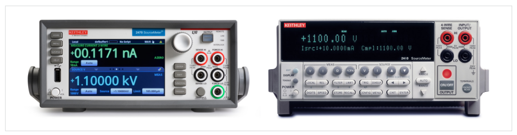
Some of the initial difference should be obvious. Notice the complete difference in the front panel. The 2410 uses a 2-line Vacuum Fluorescent Display (VFD) and a total of 31 functional front panel buttons compared to the 2470’s five-inch, full color,high resolution capacitive touch screen and only 10 physical function keys and buttons. Another difference is the control knob on the 2470. The control knob helps the user navigate the touchscreen and interact with options without even touching the screen. Additionally, the 2470 has a USB port on the front panel for saving data and screen captures.
Usability
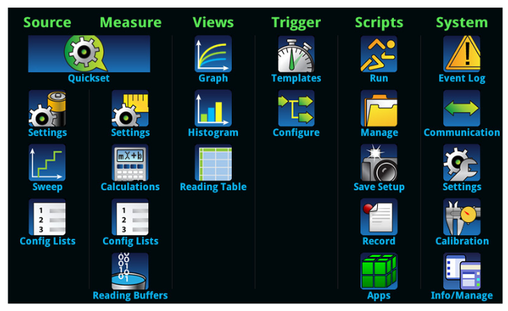
A big advantage the 2470 has over the 2410 is in the area of usability and user experience. The 2470 uses a flat icon-driven menu structure as shown in Figure 5 for fast instrument configuration including setting up IV test sweeps which will be discussed shortly. The iconic menuing approach is far superior to the menuing used on the 2410, which more resembles that of an operating system file folder. This means it could be difficult to find what you want to configure, and the settings could be a few layers deep. This is not efficient, and it does result in many users raising issues on how hard it is to navigate the menus from the front panel.
Why does the 2470 use the icon menuing approach and why use a touchscreen? Why not use a soft-key menu system? Touchscreens are the next step in the “faster time to answer” progression. The “see it, touch it, do it” quality of touchscreens not only makes these products fun to use but has made them more accessible to those who might otherwise be hesitant to try them. Touchscreens support faster, more intuitive learning, and faster setup times. And, because their operation is so intuitive, touchscreens can also give users more confidence in what they’re doing, drastically reducing user learning curves and training requirements while improving accuracy and efficiency.
With the 2470, operators at all levels of testing sophistication can become expert users practically from the first touch because its intuitive design is highly “learnable.” On-board, context-sensitive help even eliminates the need to consult a user manual to get the instrument up and running and minimizes the need to consult a manual during use. With simplified setups configured from the front panel, the 2470 supports faster time to measurement and drastic improvements in test productivity.
Some may question whether this graphical instrument interface approach is for everyone or only for novice or infrequent users. Some experienced instrument users might be hesitant to adopt touchscreen technology because they’re accustomed to working with front panels with buttons, keys, and knobs and need the tactile feedback that pressing a button or turning a knob provides. The good news with the 2470 is that the physical and touchscreen buttons have audio feedback when pressed and the knob incorporates a tactile feel when turning and pressing it. The touchscreen displays results using larger, more legible numerals and fonts, provide more details about the measurement, and offers graphing capabilities, which earlier single- or dual-line VFD displays couldn’t provide. The intuitive, highly learnable nature of touchscreen-based interfaces can also drastically reduce training time, increase operator accuracy, and improve overall operational efficiencies, which helps drive down the cost to own.
Sweep configurations
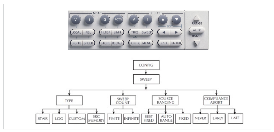
As previously mentioned, the 2410 provides three sweep types, linear, log, and custom sweeps. Configuring a sweep in the 2410 requires a number of menu and pushbutton selections as you can see in Figure 6. Configuring a sweep starts by pressing the CONFIG button on the front panel and working through various selections from the sweep configuration menu tree. This can be time consuming and prone to making mistakes.
The 2470 can perform linear staircase, logarithmic staircase, linear dual staircase, logarithmic dual staircase, and custom sweeps from the front panel or from a remote interface. Setting up sweeps is simple. You press theMENU key from the front panel. Then under Source column of the menu, touch the Sweep icon. The SWEEP SETTINGS screen is displayed. Everything you need to create a sweep is available in a single, scrollable UI. The screen is swipeable to see all of the options available. This eliminates the need to deal with all the cumbersome menuing on the 2410, saving valuable time.
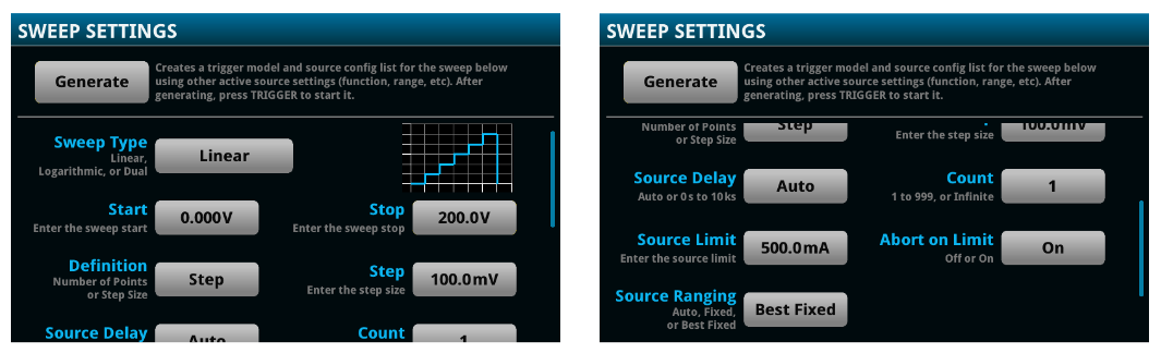
When you generate a sweep, the 2470 creates a trigger model and source configuration list using other active source settings (function, range, etc.). After the sweep has been generated all you have to do is press the TRIGGER key to start the sweep.
Displaying results
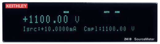
The 2410 displays the measured voltage or current on the primary line and the current or voltage source value and compliance value on the secondary display as shown in Figure 8. If you want to look at the results of a sweep, you need to recall the results from the menu and display each one individually, which could be a time consuming task. The only other option would be to download under PC control the test results back to the PC for analysis in Excel.
The user interface on the 2470 is quite different. The 2470’s home screen has three display regions(Figure 9).
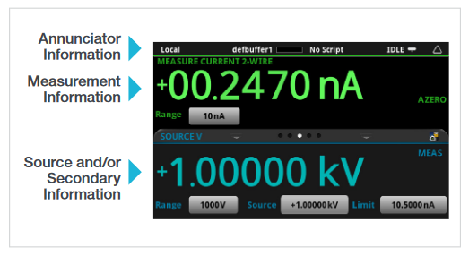
The on-screen buttons indicate the configuration settings,including the measurement range and set values. When the instrument is in auto-ranging mode, the display will also indicate the range on which the instrument is operating and update as ranges change.
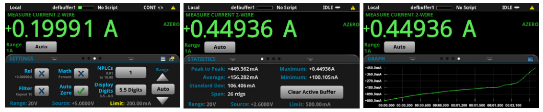
The touchscreen’s swipe capability in the Source and/or Secondary Information section simplifies and allows you to view other detailed measurement information quickly without the need to navigate a confusing menu structure. Figure 10 illustrates three typical swipe views.
One of the superior values of the 2470’s display compared to the 2410 is the ability to convert raw data to information right at your fingertips. A full graphical plotting window converts raw data and displays it immediately as useful information, such as semiconductor I-V curves and time-based waveforms. The instrument supports exporting data to a spreadsheet for further analysis, dramatically improving productivity for research, benchtop testing, device qualification, and debugging.
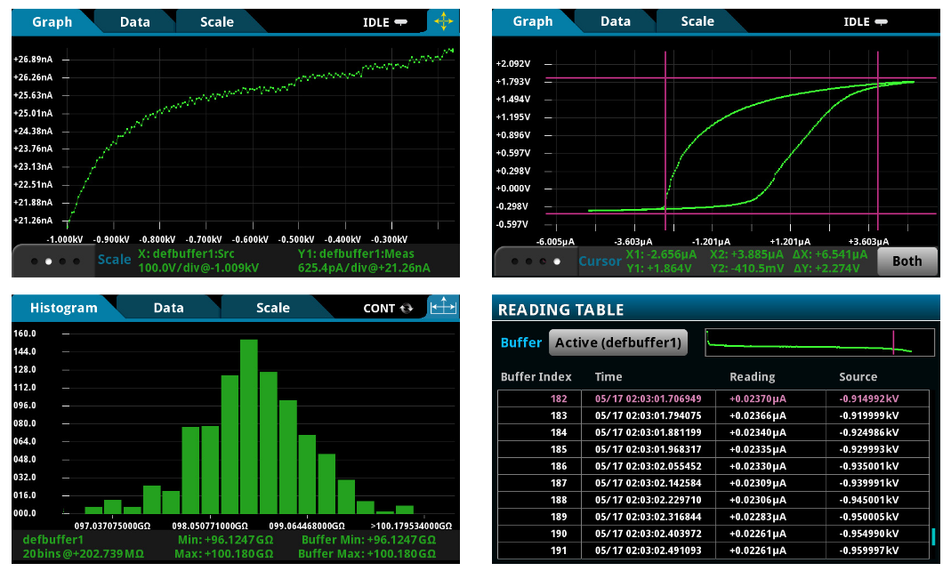
The graph and histogram charts support pinch and zoom to get deeper insights of a particular part of the plot. The 2470 also supports vertical and horizontal cursors, just like on an oscilloscope, which you can adjust to get more detailed information.Finally, the READING TABLE view enables you to scroll through all of the readings and actually see where the readings fall on the plot. This is far superior to the 2410 where you can only look at one data point at a time.
Instrument Triggering
It’s not uncommon with instrumentation to create triggering configurations which enable the instrument to execute actions based on a particular event. Both the 2410 and 2470 have the means of triggering based on certain events,but there are differences between the trigger models implemented on both SMUs.
With most SMUs, the primary actions of the trigger model are Source, Delay, and Measure. The source action outputs the programmed voltage or current value, and the programmed delay provides a settling period for the source before the measurement is performed.
The 2410’s trigger model of two layers, Arm and Trigger,is shown in Figure 12 . Programmable counters allow operations to be repeated, and various input and output trigger options are available to provide source-measure synchronization between the SourceMeter and other instruments.
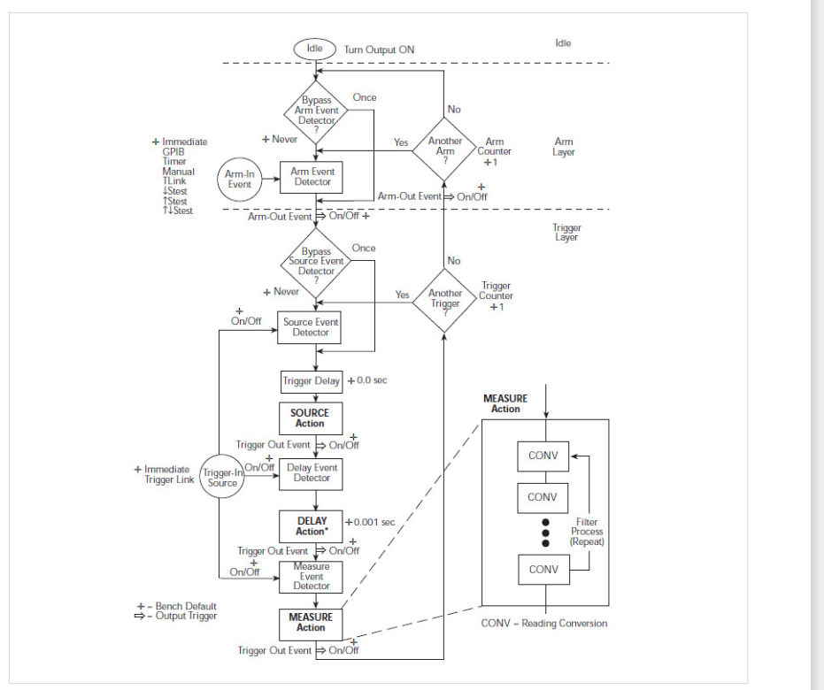
The trigger configuration tree looks as follows:
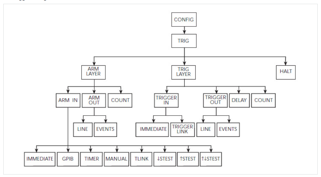
The operation of the trigger system is vastly different on the 2470 and much more flexible. Where the 2410 only gives you two layers of triggering, the 2470 offers up to 63 block levels,making it more user configurable versus being locked into a fixed two layer system.
The 2470 incorporates Keithley’s TriggerFlow®triggering system, which provides user control of instrument execution.TriggerFlow diagrams are created in much the same way that flow charts are developed, using four building blocks:
- Wait – Waits for an event to occur before the flow continues
- Branch – Branches when a condition has been satisfied
- Action – Initiates an action in the instrument, for example,measure, source, delay, set digital I/O, etc.
- Notify – Notifies other equipment that an event has occurred
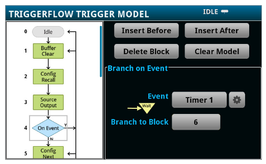
A TriggerFlow model using a combination of these building blocks can be created from the front panel or by sending remote commands. With the TriggerFlow system, users can build triggering models from very simple to complex, depending on the needs of the application. The 2470 also includes basic triggering functions, including immediate, timer, and manual triggering.
Programmability
Both the 2410 and 2470 are highly programmable for remote operation. Both the 2410 and 2470 uses the Standard Commands for Programmable Instruments (SCPI) protocol. SCPI defines a standard for syntax and commands to use in controlling programmable test and measurement devices. It is widely implemented by most test and measurement instrument suppliers.
The goal of SCPI is to provide a uniform and consistent command set for the control of test and measurement instruments. The same commands and queries control corresponding instrument functions in SCPI equipment, regardless of the manufacturer or the instrument type. However, despite SCPI’s intended function as a universal command set, the simple fact that new features are implemented with each new iteration of an instrument means that SCPI command sets will vary between instruments. This is the case with the 2470 given it has more capabilities and options than the 2410.
The main hurdle to overcome before taking the initiative to use a different command set is learning the new one,however adjusting to the nuances of a new SCPI command implementation is required every time a different instrument is in use, so it is not a hurdle that users are unfamiliar with.
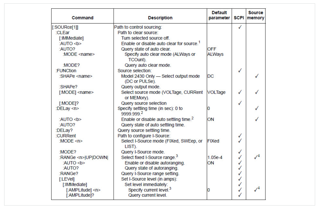
The SCPI command format was developed to be selfdescriptive. Each command is intended to describe its own function. All SCPI commands have an extended and abbreviated form. The more verbose form aids in user understanding as the commands hold more characters to help better define the action the specific command performs. The advantage of the abbreviated form is that the user can achieve the same outcome sending fewer characters. Every ASCII character sent and received takes time to propagate from sender to receiver. Therefore, fewer characters translate to less communication time. An example of SCPI commands used in the 2410 is shown in Figure 15.
Not only does the 2470 have an SCPI programming mode for those who wish to continue programming in that format,the 2470 also offers a scripting mode call TSP® for creating simple to very complex applications. Let’s explore TSP and scripting.
Keithley’s Test Script Processor (TSP) is a flexible hardware/ software architecture that allows message-based programming, much like SCPI, with enhanced capabilities for controlling test sequencing/flow, decision-making, and instrument autonomy. TSP-enabled instruments operate like conventional SCPI instruments by responding to a sequence of commands sent by the controller. You can send individual commands to the TSP-enabled instrument the same way you would when using SCPI with any other instrument. Making the switch to TSP will afford you improved throughput, access to additional interfacing options between both the PC and other instruments, and the convenience of autonomous instrumentation when desired.
The use of an on-board Test Script Processor in the 2470 has made it possible to create a “smart” instrument, with builtin decision making capabilities, which reduces the need to communicate so frequently with an external controller. This approach to test system design allows smart instrument systems to be much more efficient than those that rely on standard SCPI-based programming. TSP encompasses both the TSP command set and the TSP scripting language. The TSP scripting language is based on Lua, and when used together with the TSP command set, allows for logic and subroutines that would normally reside on a PC to run inside the instrument, which reduces the amount of data and number of messages sent over the communications bus by a considerable amount.
Making the switch to the TSP command set from SCPI is a simple matter of swapping analogous commands. While that concept seems daunting, it is not so different from learning the different SCPI command sets for each individual instrument model.
The example shown in Figure 16 utilizes a 2470 SourceMeter® source measure unit to produce an I-V sweep characterization of a solar cell. The voltage is swept from 0 V to 0.55 V in 56 steps. The resulting solar cell current is measured. The current and voltage measurements are stored in a default data buffer (defbuffer1). Finally, the buffer data is returned.
| SCPI | TSP |
| "*RST" | reset() |
| "SENS:FUNC 'CURR'" | smu.measure.func = smu.FUNC_DC_CURRENT |
| "SENS:CURR:RANG:AUTO ON" | smu.measure.autorange = smu.ON |
| "SENS:CURR:RSEN ON" | smu.measure.sense = smu.SENSE_4WIRE |
| "SOUR:FUNC VOLT" | smu.source.func = smu.FUNC_DC_VOLTAGE |
| "SOUR:VOLT:RANG 2" | smu.source.range = 2 |
| "SOUR:VOLT:ILIM 1" | smu.source.ilimit.level = 1 |
| "SOUR:SWE:VOLT:LIN 0, 0.55, 56, 0.1" | smu.source.sweeplinear("SolarCell", 0, 0.55,56, 0.1) |
| "INIT" | trigger.model.initiate() |
| "*WAI" | waitcomplete() |
| "TRAC:DATA? 1, 56, "defbuffer1", SOUR, READ" | printbuffer(1, 56, defbuffer1.sourcevalues,defbuffer1.readings) |
Figure 16: A 2470 example comparing SCPI to TSP commands.
This example could be taken a step further by using these basic TSP commands in conjunction with the full power of the TSP scripting language. The Test Script Processor in enabled instruments uses on-board scripting with the TSP command set.This allows for data interpretation to be handled locally by the instrument, as opposed to remotely by a controlling PC running programs such as Microsoft Excel. The calculations required to identify key points of data can be done by the instrument and displayed on the front panel or returned to an external computer.
The 2470’s TSP capability can help improve test throughput and increase the overall functionality of the SMU. TSP affords the user a multitude of advantages over SCPI, including the ability to return multiple readings at once, improved throughput, and better readability. Flexibility is a key asset of the TSP command set, allowing the user to tune their experience to their specific needs. TSP can be used in a similar manner to SCPI by being run from a controlling PC with TSP commands acting as analogous replacements to SCPI commands. It can be used to write scripts that are run locally on the instrument, or to manage large networks of other TSP enabled connected instruments.
To learn more about TSP and transitioning from SCPI to TSP,we encourage you to read the App Notes “How to Transition Code to TSP from SCPI” and “How to Write Scripts for Test Script Processing (TSP®)”, both available at www.tek.com.
Summary
The 2470 is a new and modern source measure unit with an extremely powerful user interface, triggering, programming, and configuration capability compared to the legacy 2410. The 2410 has served customers extremely well for over 25 years, but its life is approaching the end. The 2470 is a great replacement for the 2410, capable of serving the same applications and making it much easier for the user to do more with the instrument. The graphical SMU is designed such that you spend less time learning the SMU, but spend more time making measurements, reviewing results and information faster to make better engineering decisions. When time to market is so critical today to achieve a competitive advantage, the 2470 will help you achieve that goal. With all the new capabilities of the 2470, combined with Keithley’s decades of expertise in developing high precision, high-accuracy SMU instruments, the 2470 will be your “go-to instrument” for high-voltage source and low-current measurement applications in the lab and in the test rack.
 |
 |
|
| Key Feature Comparison | 2470 | 2410 |
| User Interface | 5-in Capacitive Touch | Multi-Button VFD |
| Maximum V | 1100 V | 1100 V |
| Maximum I | 1 A | 1 A |
| Max DC Power | 20 W | 20 W |
| Min Current Range | 10 nA | 1 µA |
| Measurement Resolution (I/V) | 10 fA / 100 nV | 1 pA / 100 nV |
| Memory Capacity | >1,000,000 Points | 5000 Points |
| Basic Accuracy | 0.012% | 0.012% |
| Input Connectors | F: Banana / R: HV Safety Triax | F: Banana / R: Banana |
| Programming Language | SCPI, TSP | SCPI |
| Communications Interface | GPIB, USB, Ethernet | GPIB, RS-232 |
| Safety Interlock | True Interlock | None |