Contact us


Call us at
Available 6:00 AM – 5:00 PM (PST) Business Days
Download
Download Manuals, Datasheets, Software and more:
Feedback
Automotive SENT Sensor Bus Troubleshooting

Automotive SENT Sensor Bus Troubleshooting
SENT bus (also known as SAE J2716) is a cost-effective, precise way to transmit sensor data to ECUs, with key advantages over analog PWM. But while the pulse-width encoding used in the standard is reliable, it is very difficult to decode by hand. Adding automated decoding and triggering to your oscilloscope, greatly simplifies troubleshooting.
How the SENT bus works
SENT transmits data in 4-bit nibbles between two falling edges, hence the name “Single Edge Nibble”. Timing of the SENT bus is measured in ticks, with each tick typically 3 μs wide. Each nibble starts with a logic-low period of at least 5 ticks, followed by a variable-length logic-high period representing the encoded data value. A 0000 binary data value is represented by a logic-high duration of 12 ticks. A 0001 binary data value is represented by a logic-high duration of 13 ticks, and so on, up to a 1111 binary data value is represented by a logic-high duration of 27 ticks.
- Electrical signaling: signal line, a +5V supply voltage line, and a ground
- Signal levels: Low < 0.5V and high > 4.1V
- Data rate: up to 30 kb/s
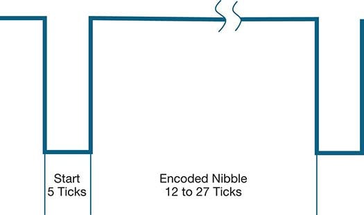
Single Edge Nibble encodes four bits in a single pulse.
Decoding fast channel SENT messages
The SENT “fast channel” message begins with a sync pulse where the time between successive falling edges is 56 clock ticks. The SENT message is 32 bits long, consisting of:
- Four bits of status / communication information (12-27 ticks)
- Six 4-bit nibbles of data (12-27 ticks each)
- Four bits (12-27 ticks) of CRC for error detection
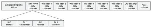
A fast channel message comprised of sync pulse, status nibble, six data nibbles, CRC and optional pause.
Decoding slow channel SENT messages
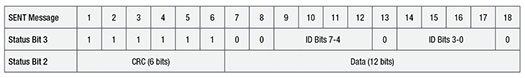
A slow channel message transmitted in the status nibble of 18 consecutive messages
The SENT standard also supports “slow channel” messages, in which data is transmitted 1 or 2 bits at a time via bits 2 and 3 of the 4-bit status nibble, in 16 or 18 successive fast channel messages. These bits are accumulated to build the slow channel message.
Setting up an oscilloscope for SENT decoding and triggering
The SENT bus is a single-ended, ground-referenced signal. Although the oscilloscope can acquire and decode the bus using standard single-ended probing, the signal fidelity and noise immunity may be improved by using differential probing.
On Tektronix oscilloscopes equipped with SENT decoding and triggering, pressing the front panel Bus button enables you to define inputs to the scope as a bus. To enable the oscilloscope to decode the packet data, you enter some basic parameters regarding your specific SENT implementation.
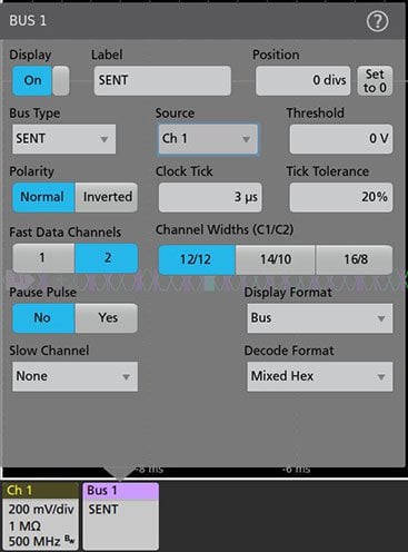
Parameters for setting up SENT decoding and triggering on a 5 Series MSO.
Viewing a decoded SENT bus on the oscilloscope
The time-correlated waveform and bus decode display is useful for looking at system timing relationships. The decoded bus waveform indicates the elements of a SENT fast-channel message, including:
- Sync pulse
- Status nibble
- Data
- CRC
- Pause (if applicable)
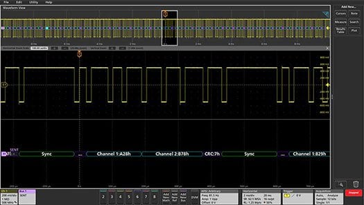
A decoded fast channel SENT message is shown at the bottom of this 5 Series MSO display.
Interpreting slow channel SENT messages
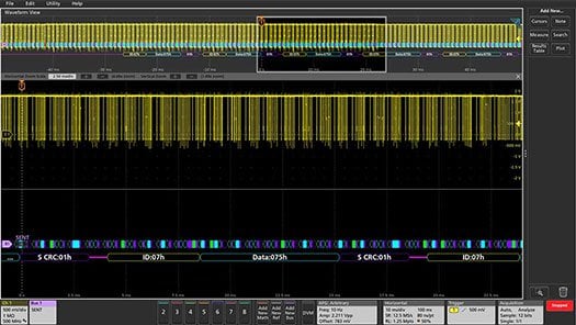
Slow channel SENT bus packets displayed below fast channel packets
The decoded SENT bus can display both fast and slow channel packets in a single waveform display, with the slow channel packets shown below the fast channel packets.
Triggering and searching on SENT bus values
Bus triggering tells the oscilloscope to capture all the input signals based on a specified bus event. That event will be positioned at the trigger point. For the SENT bus, the 5 Series MSO can be set up to trigger on:
- Start of Packet
- Fast channel data
- Pause Pulse
- Error
Similar to bus triggers, the oscilloscope can also search through all its aqcuired data, for bus conditions that match specified values.
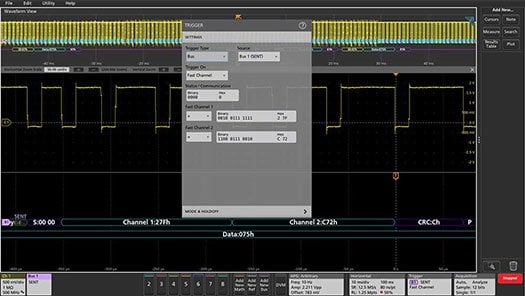
Setup to trigger on status value of 0000 binary, fast channel 1 data value 0x27F, and fast channel 2 data value 0xC72.
Featured Content
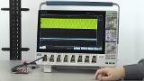
SENT Bus Decode and Trigger on 5 Series MSO
Video
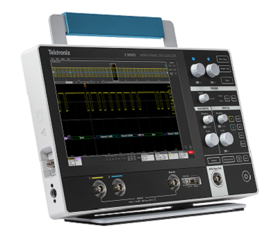
Up to 6 channels in a bench-friendly scope
4 Series MSO Mixed Signal Oscilloscope
- 13.3-inch HD display: view multiple waveforms and decoded bus activity
- Available with 4 or 6 FlexChannel® inputs for a wide system view
- Versatile triggering and search to locate specific bus traffic or errors
Get unprecedented visibility into your ECU designs
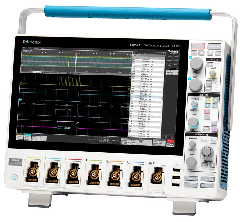
5 Series MSO Mixed Signal Oscilloscope

- 15.6-inch HD display: view multiple waveforms and decoded bus activity
- Available with 4, 6, or 8 Flexchannel inputs, for a wide system view
- Versatile triggering and search to locate specific bus traffic or errors
Portability and power in a compact form factor
2 Series MSO Mixed Signal Oscilloscope
- 70 MHz to 500 MHz bandwidth
- 2 or 4 analog channels; 16 digital channels (optional)
- 10.1-inch capacitive touchscreen display