

Cellular networks continue to grow at a rapid pace around the world. In many regions, network operators are bringing cdma2000 1xEV-DO capabilities into commercial service as part of the evolution towards Third-Generation (3G) networks.
This technical brief will introduce the reader to cdma2000 1xEV-DO wireless network concepts and will provide understanding and insight into the air interface. In order to assist maintenance personnel in achieving the high data rates promised by EVDO technology, a particular focus will be given to base station forward-link transmissions. We begin with a review of the evolution of cdma2000 1xEV-DO, followed by a description of the forward-link air interface and key RF parameters. We will then discuss some of the testing challenges in cdma2000 1xEV-DO and describe state-of-the-art test tools that can help wireless networks meet quality of service (QoS) goals.
Evolution of cdma2000 1xEV-DO
Code division multiple access (CDMA) is a second-generation cellular technology that utilizes spread-spectrum techniques. CDMA came to market as an alternative to GSM-based frequency-hopping architectures. Basic CDMA systems deliver approximately 10X the voice capacity of earlier analog systems.
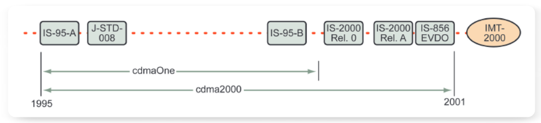
The first CDMA standard commonly deployed by wireless service providers was IS-95A. It contained the core elements for voice transmission that are present in all later versions. Additional standards such as J-STD-008 and IS-95B were released after IS-95A to enhance performance and accommodate various frequency bands around the world. The series of standards released in this time period are collectively known as cdmaOne. The CDMA wireless technology evolution is shown in Figure 1.
More recently, IS-2000 Release 0 and IS-2000 Release A were introduced. Commonly referred to as cdma2000 or cdma2000 1xRTT (Radio Transmission Technology),these standards increased voice service capacity and improved data transmission rates. Finally, cdma2000 1xEV-DO (IS-856) was released to further increase data transmission rates.
The acronym EV-DO stands for "Evolution-Data Only" (sometimes referred to as "Data Optimized"). The 3GPP2 standards group defines cdma2000 1xEV-DO in the C.S0024-0 v4.0 standard (www.3gpp2.org). Similarly, the Telecommunications Industry Association (TIA) defines the architecture in specification IS-856 in the United States. For the sake of simplicity, cdma2000 1xEV-DO will be referred to in the balance of this document as "EVDO".
While cdma2000 1xRTT is capable of data rates of approximately 144 kbps, the higher data rates significantly reduce the ability of the CDMA carrier to support voice traffic channels. As a result, many wireless service providers have been reluctant to allow high data rates in 1xRTT and, instead, have opted to implement a dedicated carrier using EVDO technology.
EVDO increases network data capacity to a maximum of approximately 2.4 Mbps. This new benchmark allows networks to offer true high-bandwidth data services such as streaming video within their current CDMA spectrum.
EVDO Overview
Cdma2000 1xRTT brought packet switching to CDMA networks. EVDO dramatically enhances the packetswitched capabilities, while coexisting with many of the 1xRTT features.
Packet-switched systems conserve resources, using network capacity (bandwidth) only when there is data to be transferred. The variable nature of packet-switched systems makes it difficult for older wireless systems based on dedicated channels and circuit switched technologies to provide the data rates now expected in modern packet switched networks. The EVDO system implements a number of techniques that make it more compatible with high data rate packet switch networks.
The EVDO forward link is designed to optimize the transmission of data and, at the same time, use the allotted spectrum more efficiently. Its success in achieving these goals depends on three key attributes.
Time Division Multiplexing (TDM)
One major difference between EVDO and 1xRTT is EVDO’s use of TDM. Unlike traditional TDM systems where each user is assigned a particular timeslot, EVDO assigns timeslots dynamically depending on the needs and reception conditions of each user. The use of TDM also allows all available power to be dedicated to one user, resulting in better signal quality and, ultimately, higher data rates.
New Modulation Formats
cdma2000 systems utilize Quadrature Phase Shift Keying (QPSK) to transmit data. In order to transmit at higher data rates, EVDO also implements 8-Phase Shift Keying (8PSK) and 16-Quadrature Amplitude Modulation (16QAM). While 8PSK and 16QAM are an effective method of increasing data rates, they are more susceptible than QPSK to transmission errors due to environmental conditions such as interference.
Highly Adaptive Data Rates
In addition to the modulation format, other features are present in EVDO to increase and decrease rates for optimal performance and data throughput. This includes special algorithms to schedule packets based on fading conditions, prediction of expected rates, and a host of rate control mechanisms.
The Forward Link RF Interface
To implement EVDO, operators must devote a 1.25 MHz CDMA carrier to packet data. An EVDO carrier is used for packet data only (although other CDMA carriers within the system may still carry voice traffic). EVDO utilizes the same chip rates and filters used in cdma2000 1xRTT and earlier CDMA systems, so spectrum utilization is identical to that of cdma2000.
TDM
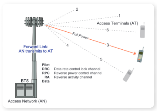
As stated earlier, EVDO uses TDM to dedicate all transmit power—and the corresponding data bandwidth—to just one Access Terminal (AT) at a time. This scheme is illustrated in Figure 2.
Using TDM and dedicating all power to a single AT is very different than the method used in 1xRTT. In 1xRTT, transmissions to users are differentiated by Walsh code and occur in parallel. The number of simultaneous transmissions in 1xRTT, transmit power levels, and various other factors determine the achievable the data rate. EVDO transmits data to one AT at a time, allowing all signal power to be dedicated to that AT.
To make better use of available bandwidth, EVDO does not pre-assign timeslots. Instead, the Access Network (AN)makes the assignment dynamically. This flexibility allows ATs to receive more or less timeslots based on need, priority,and reception conditions.
Channel Structure
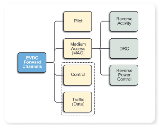
The EVDO forward link channel structure contains four channels: Pilot, Medium Access (MAC), Control, and Traffic (data). The medium access channel (MAC) further subdivides into three sub-channels: Reverse Activity, Data Rate Channel (DRC), and Reverse Power Control. The channels are illustrated in Figure 3.
Of the channels shown in Figure 3, only the Control channel and MAC are used to transmit data to multiple ATs at the same time. Before describing the function of each channel in detail, it will be useful to understand the timing of an EVDO forward link transmission.
EVDO Channel Format
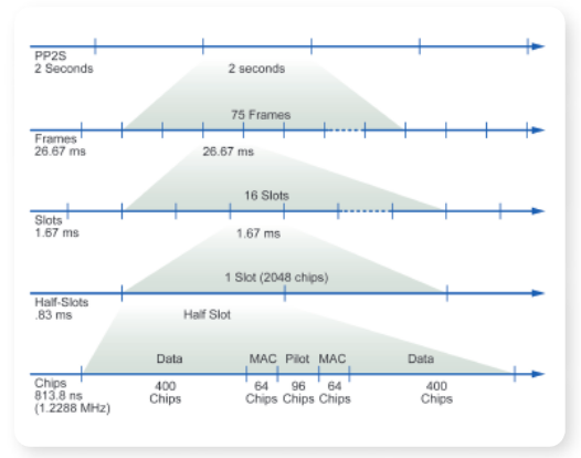
The EVDO forward link carrier occupies a bandwidth of 1.25MHz. The forward link transmission consists of time slots that are 2048 chips in length. Each timeslot is further subdivided into half slots that are 1024 chips in length. Groups of 16 slots are known as frames. The hierarchy of timing assignments is shown in Figure 4.
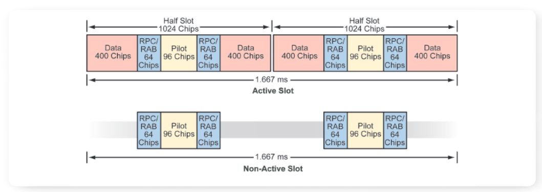
As depicted in Figure 5, the Pilot, MAC and Traffic or Control Channels are time-division multiplexed. A slot that passes without traffic or control data is considered an idle slot. During this time the sector transmits the Pilot and MAC Channels only, reducing potential interference with other sectors.
During idle slots, the Data interval transmit power is reduced by at least 7 dB relative to the Pilot/MAC interval.This helps reduce interference to adjacent sectors. Note that a PN Short Code identifying the AN’s sector is mixed with every time slot.
Pilot, MAC, Data and Control Channel Configuration Details
Pilot Channel
The Pilot Channel acts as the forward link signal’s main timing reference. As in 1xRTT, all EVDO ANs derive their timing from GPS and transmit synchronously throughout the system. The power level of the pilot determines the size (or footprint) of the cell.
The Pilot Channel transmits the PN sequence with a fixed delay (PN Offset) from the GPS timing reference. Each AN uses a different PN Offset to distinguish itself from other ANs. The pilot acts as a beacon to mobile stations within range. ATs use the Pilot power level to set initial power levels and to arbitrate Mobile Assisted Handoffs (MAHO) between other ANs (other PNs).
Medium Access Channel (MAC)
Unlike data in the Traffic Channel, the MAC is used to send information to multiple ATs simultaneously. This is done in a similar manner to 1xRTT. Each AT is assigned one Walsh code and uses that code to acquire its own information.
The MAC’s primary role is control of AT power levels and data rates. MAC data is sent to many different ATs at once, separated by one of 64 Walsh codes. MAC channels 0 to 3 are reserved. Channel 4 is used to send the Reverse Activity Bit (RAB), requesting a higher or lower average reverse data rate. Channels 5 to 63 are used to send Reverse Power Control (RPC) and Data Rate Control Lock (DRC Lock) information to each AT. The RPC is used for power control and the DRC Lock indicates that the AN can not receive the AT’s Data Rate Control channel information. The DRC Lock information is sent by periodically replacing the RPC bit.
Preamble (Traffic Channel Control)
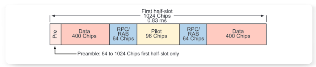
As illustrated by Figure 6, the first half-slot transmitted within a user data packet includes a preamble. The preamble is transmitted in the same timeslot as Traffic data and can vary from 64 to 1024 chips (extending into the second half slot if necessary). All ATs decode the preamble.
There are 64 unique preambles. Preambles 5 to 63 indicate that the associated packet data is intended for a single AT. Preambles 2 and 3 indicate that the associated packet data is system Control information intended for all ATs.Preambles 0, 1, and 4 are currently unused.
Traffic Channel
Data in the Traffic Channel undergoes a series of complex processes including turbo coding, scrambling of the content to randomize the data, interleaving, and ultimately mapping to I and Q values for transmission.
EVDO transmission data rates vary from 38.4 kbps to 2457.6 kbps, dependent on AN to AT link quality. Poor
quality links due to inaccurate modulation, noise, interference, or distortion will receive additional error correction and utilize a slower modulation format (QPSK).Correspondingly, "good" signals require less error correction and utilize faster modulation formats (8PSK or 16QAM).
EVDO data rates are determined by the coding rate,modulation, and repetition factor, as summarized in Table 1.
| DRC Index | Data Rate kb/s | Slots | No.of Bits | Code Rate | Repetition Factor | Modulation Format |
| 1 | 38.4 | 16 | 1,024 | 1/5 | 9.6 | QPSK |
| 2 | 76.8 | 8 | 1,024 | 1/5 | 4.8 | QPSK |
| 3 | 153.6 | 4 | 1,024 | 1/5 | 2.4 | QPSK |
| 4 | 307.2 | 2 | 1,024 | 1/5 | 1.2 | QPSK |
| 5 | 307.2 | 4 | 2,048 | 1/3 | 2.04 | QPSK |
| 6 | 614.4 | 1 | 1,024K | 1/3 | 1 | QPSK |
| 7 | 614.4 | 2 | 2,048 | 1/3 | 1.02 | QPSK |
| 8 | 921.6 | 2 | 3,072 | 1/3 | 1.02 | 8PSK |
| 9 | 1,228.8 | 1 | 2,048 | 2/3 | 1 | QPSK |
| 10 | 1,228.8 | 2 | 4,096 | 1/3 | 1.02 | 16QAM |
| 11 | 1,843.2 | 1 | 3,072 | 2/3 | 1 | 8PSK |
| 12 | 2,457.6 | 1 | 4,096 | 2/3 | 1 | 16QAM |
Code rate is the amount of redundancy added to the data stream to ensure accurate reconstruction of the signal upon demodulation. For the slowest EVDO data rate (38.4 kbps),5 bits of data are created for each bit of actual data. At the highest rate (2457.6 kbps), 3 bits are created for every 2-bits of actual data.
In addition to changing the coding rate to protect data,EVDO will repeat the data. As can be seen from Table 1,the amount of data transmitted in a packet is decreased at lower data rates and the number of slots required to transmit the data is increased.
Finally, more efficient modulation formats are used at the higher data rates to improve performance further. At lower rates, QPSK modulation is used to provide 2-bits of data per symbol. At data rates of 921.6 Mbps and 1,843.2 Mbps the data receives 8PSK modulation resulting in 3-bits per symbol. At the data rates of 1,228.8 Mbps and 2.4576 Mbps the data is modulated with 16QAM, equivalent to 4-bits per symbol.
Keeping Track Of RF Conditions
In the real world of mobile operation, conditions in the RF environment change constantly. In EVDO systems,the AN and AT constantly assess the situation and make adjustments. Other techniques, such as packet scheduling and Automatic Request Control (ARQ), further optimize EVDO for a changing environment.
AN and AT monitoring
The AT constantly monitors Packet Error Rates (PER) and the RF environment in which it is operating. Based on these measurements, the AT calculates the appropriate modulation, coding and data rate in each successive time slot.This information is then transmitted up the 4-bit Data Rate Control (DRC) reverse link channel to inform the base station. This allows for flexible data rate assignment to each AT on the sector.
At the same time, the AN monitors the AT’s pilot channel,assessing environmental conditions, like fading, in order to predict rates and schedule packets. The AN manages fast power control for numerous ATs simultaneously through the reverse power control channel.
Scheduling
The EVDO forward link utilizes scheduling algorithms to take advantage of multi-user diversity and fading to increase data throughput. Although the standard does not call out one specific scheduling algorithm, many operators achieve an acceptable balance between (maximized) system capacity and fairness among individual ATs by using a technique known as the proportional fair scheduling algorithm. In a static channel condition in which only white noise is present1, the algorithm gives each AT equal transmission time.
In an environment that experiences gradual fading, the proportional fair scheduling algorithm can give preference to an AT whose channel is trending stronger ("up-fade"). Simultaneously, it may delay data transmission to ATs that are trending weaker ("down-fading"). In effect, this is a form of diversity reception, though it serves multiple ATs rather than just one receiver. Ultimately this technique tends to increase sector throughput by directing more data to the ATs with better link quality and delaying transmissions to ATs where poor link quality may improve.
Hybrid Automatic Request Control
The hybrid Automatic Request Control (ARQ) scheme is another tool that boosts spectral efficiency. Packets are sent incrementally as sub-packets, transmitted in discrete time slots in interlaced fashion. There are three slots between any two related sub-packets. The packets are transmitted with enough redundancy to make reception of one slot adequate for decoding the entire packet. Each time the packet is repeated, the likelihood of successful decoding by the AT increases. As soon as a packet is decoded, perhaps before all repeats occur, the AT terminates the transmission.
RF Modulation Methods
As summarized in Table 1, EVDO uses one of three modulation formats to encode the data stream information onto the RF signal. As indicated earlier, the selection of the format depends on RF environmental conditions.
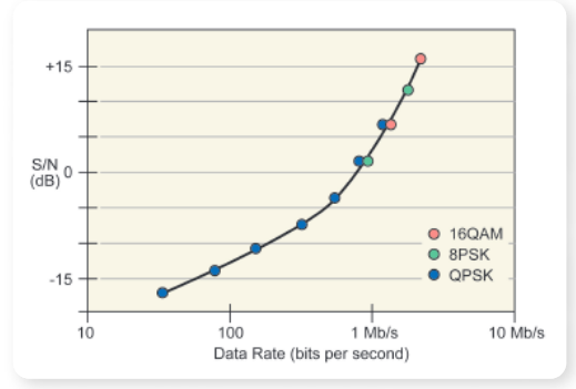
The AT’s distance from the AN’s transmission antenna greatly affects the strength of the received signal. Distant ATs receive less power from the serving AN, more interference from adjacent ANs, and greater relative noise from the environment. All these factors increase the signal to noise ratio (S/N), resulting in lower data rates. Figure 7 describes the relationship between signal to noise, data rate, and modulation type.
EVM - Error Vector Magnitude
EVM is a measurement which evaluates the signal quality. EVM is computed from the vector difference between the actual received signal and a calculated,ideal reference signal (Figure 8).
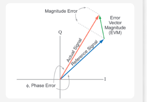
EVM is simply a visualization of the digital modulation process. The horizontal axis represents the real (I) component of the transmitted signal, while the vertical axis maps the imaginary (Q) component. Using this depiction, the magnitude and phase of every symbol state on the modulation constellation can be shown.
The symbols represented by the modulated signal need to be demodulated and decoded within discrete decision points in the constellation in order to be error free. These points are like "targets" that the modulated signal’s phase and magnitude components must hit, within a tolerance, to support acceptable error rates. This tolerance is the EVM (Error Vector Magnitude), a key measurement of signal quality. EVM is computed from the vector difference between the actual received signal and a calculated ideal reference signal. When EVM is high, the system has difficulty decoding symbols. Degradation of the received RF signal due to impairments such as interference, noise, modulation quality, and distortion along the RF path will increase EVM.

QPSK Modulation
Quadrature phase shift keying is the simplest and most robust of the available EVDO formats. QPSK modulation has four different phase shifts and maps 2-bit values to each of the four possibilities. It delivers the lowest data rate of the three modulation methods, but it has a high immunity to errors. The EVM can be quite large before there is a possibility of one symbol being confused with another. Figure 9 shows an IQ diagram for QPSK modulation.
Notice that the error vector tolerance (the radius described by the red arrow) is large; in fact, almost as large as the quadrant itself. QPSK is suitable for the worst-case transmission conditions near the AN’s outer cell boundary.
8PSK Modulation
8PSK modulation takes over to deliver higher EVDO data rates as the transmission environment improves. This scheme allows 8 different phase shifts and mapping of 3-bit data patterns to each symbol (Figure 10). The data transmission rate increases by 50% over QPSK modulation.
Note, however, that the radius of the maximum permissible error vector has been reduced by approximately half. The vectors have a much smaller "target" area to hit. Moreover, the ability to recover from a decoding error is worse; where QPSK-encoded signals lose 2-bits if a single decoding error occurs, 8PSK signals lose three bits for every decoding error.

16QAM Modulation
Under optimum transmission conditions, the EVDO system switches to 16QAM modulation (Figure 11) to deliver its maximum data rates. This modulation scheme requires changes in phase and amplitude to reach each decision point. 16QAM provides for 16 different phase shifts and mapping of 4-bit data patterns to each symbol. The data transmission rate increases by 100% over QPSK modulation.
Using 16QAM, the maximum allowable tolerances are reduced even further. Small errors now result in the loss of 4-bits of data. To achieve the highest EVDO data rates using 16QAM modulation, accurate modulation, a very clean RF environment, low noise, and low distortion are all required.
Measurement Issues and Challenges
EVDO is all about providing practical, high-throughput data services to mobile customers. Users are embracing these services wherever they are installed, paying a premium for the new capabilities. Consequently they have high expectations with regard to interference, dropped calls, transmission speed, and responsiveness.

A mobile web link must be more reliable than its voice-only predecessors, yet these complex high-speed links are more susceptible to problems, particularly as subscribership grows. The operator who cannot manage these challenges risks the mass defection of dissatisfied subscribers.
Historically, dropped calls have been the biggest factor in customer dissatisfaction. But operators deploying EVDO are likely to encounter the same situation that their GSM/EDGE colleagues have seen: today’s premium subscriber is most concerned about the responsiveness of his or her mobile data features. It is a challenge that, at its heart, relates to signal quality. As signal quality declines, EVDO will fall back to a very robust but slow data rate. Under these circumstances, user frustration increases and perception of value decreases accordingly. To make matters worse, these conditions will not manifest themselves in traditional network statistics like dropped call rates.
As we have seen, EVDO monitors dynamic RF environmental conditions and the AT’s responses to them. The higher the received signal quality, the higher the data rate can be.Therefore, keeping track of signal quality on the forward link is crucially important, allowing the highest data rate possible furthest from the base station.
It is a situation that implies a need for rigorous testing at installation time, and frequent preventive maintenance measurements. Of particular interest are:
Modulation accuracy including Error Vector Magnitude and Waveform Quality (Rho)
Accurate modulation is required if an EVDO system is to provide high data rates at locations far from the AN.
The TDM structure of EVDO requires multiple rho measurements made over the course of a transmission.There are separate measurements for the network equipment, for the pilot channel, and for the entire transmission including traffic.
Power measurements during transmission
Precise Power settings are critical in CDMA systems. Low power settings result in interference at cell boundaries, dropped calls, and premature handoffs. High power settings result in interference to neighboring cells and reduced capacity. Small changes as much as 1 dB can reduce AN capacity significantly.
Note that a pulsed transmission scheme such as EVDO is by definition transmitting only part of the time. Therefore the power measurement applies only to the active duty cycle. EVDO Code Domain Power specifications require code channels to be within ± 0.5 dB of the nominal value. There are additional requirements for the MAC-code channels.
Emissions, with special provisions for measurements during idle slots
Both active and idle slots have the same emission limits. However, the idle slot, as its name implies, is not "on" constantly. Therefore measurements must synchronize with the "on" state. Furthermore, amplifiers used in ANs add delays that must be accounted for when synchronizing the sampling.
Measurement Solutions Ready For Installation & Maintenance
For most network operators, the measurements just summarized are easily within the capabilities of their top technicians and benchtop tools. The real challenge is one of scale: hundreds of base stations to be outfitted with EVDO features, then tested, then maintained ever after. Operators need tools that are portable, affordable, and easy for entry-level technicians to use.
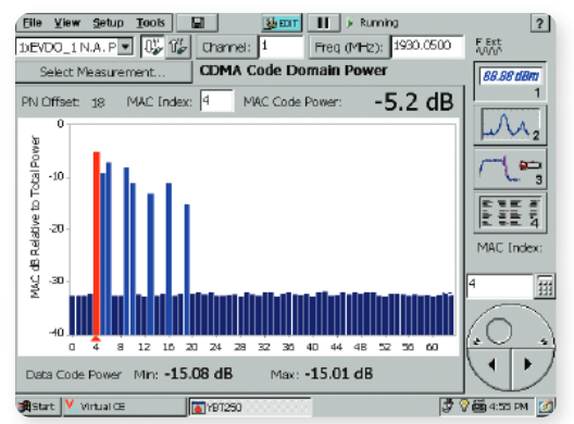
The Tektronix NetTek® analyzer is a handheld, multi-standard BTS field measurement tool. When equipped with the YBT250 test module, the NetTek analyzer is ready to troubleshoot and verify EVDO base stations quickly and easily. The YBT250 test module can be used for many other wireless standards as well, including, IS-95 and cdma2000 1xRTT.
The YBT250 test module is optimized to perform the dayto-day RF and demodulation measurement tasks that occupy the majority of a technician's time. The tool brings built-in expertise to EVDO installation and maintenance measurements, allowing users of all experience levels to complete on-site tests without difficulty. Common measurements have been optimized for quick, repeatable results.
With the cdma2000 1xEV-DO option, the NetTek analyzer can perform MAC code domain power, pilot EVM/Rho, overall EVM/Rho, PN offset, data modulation type identification, and other critical EVDO measurements. Figure 12 illustrates a MAC code domain power measurement taken from a cdma2000 1xEV-DO base station.
Conclusion
cdma2000 1X EV-DO brings important new capabilities to CDMA-based networks, and is becoming a reliable revenue generator for operators. EVDO is one of the least costly upgrades on the path to 3G technology, yet it provides unmatched data rates though its dedicated data channel. Operators, keenly aware of the benefits of bringing data features to market in the shortest possible time, are racing to qualify and install EVDO in their networks.
EVDO brings with it a host of new RF measurement considerations as technical personnel install new EVDO hardware.Each new installation on hundreds of base stations calls for a series of complex verification measurements.
In this technical brief we have discussed what makes EVDO work. In the companion piece "cdma2000 1xEV-DO Wireless Networks: Challenges in Maintenance and Testing" we examine the specific measurements that accompany an EVDO installation or maintenance procedure.
For Further Information
Tektronix maintains a comprehensive, constantly expanding collection of application notes, technical briefs and other resources to help engineers working on the cutting edge of technology. Please visit www.tektronix.com
Copyright © 2005, Tektronix, Inc. All rights reserved. Tektronix products are covered by U.S. and foreign patents, issued and pending. Information in this publication supersedes that in all previously published material. Specification and price change privileges reserved. TEKTRONIX and TEK are registered trademarks of Tektronix, Inc. All other trade names referenced are the service marks, trademarks or registered trademarks of their respective companies.
01/05 DM/WOW 2FW-18494-0