

Document number: SPEC-2001L
Specifications are subject to change without notice.
Introduction
The following pages contain the complete specifications for the Model 2001. Every effort has been made to make these specifications complete by characterizing its performance under the variety of conditions often encountered in production, engineering, and research.
The 2001 provides 5-minute, 1-hour, 24-hour, 90-day, 1-year, and 2-year specifications, with full specifications for the 90-day, 1-year, and 2-year specifications. This allows the user to utilize 90-day, 1-year, or 2-year recommended calibration intervals, depending upon the level of accuracy desired. As a general rule, the 2-year performance of the Model 2001 exceeds a 5½-digit DMM's 90-day, 180-day, or 1-year specifications. 6½- or 7½-digit performance is assured using 90-day or 1-year specifications.
ABSOLUTE ACCURACY
Based on factory calibration, all 90-day, 1-year, and 2-year specifications are absolute accuracy, traceable to the International System of Units (SI) through a National Metrology Institute (NMI).
TYPICAL ACCURACIES
Accuracy can be specified as typical or warranted. All specifications shown are warranted unless specifically noted. Almost 99% of the 2001's specifications are warranted specifications. In some cases, it is not possible to obtain sources to maintain traceability on the performance of every unit in production on some measurements (for example, high-voltage, high frequency signal sources with sufficient accuracy do not exist). Since these values cannot be verified in production, the values are listed as typical.
2001 SPECIFIED CALIBRATION INTERVALS
| MEASUREMENT FUNCTION | 24 HOUR1 | 90 DAY2 | 1 YEAR2 | 2 YEAR2 |
| DC Volts |
• |
• | • | • |
| DC Volts Peak Spikes | •3 | • | • | |
| AC Volts RMS | •3 | • | • | |
| AC Volts Peak | •3 | • | • | |
| AC Volts Average | •3 | • | • | |
| AC Volts Crest Factor | •3 | • | • |
|
| Ohms | • | • | • | • |
| DC Current | • | • | • | • |
| DC In-Circuit Current | • | • | • | |
| AC Current | •3 | • | • | |
| Frequency | • | • | • | |
| Temperature (Thermocouple) | • | • | • |
|
| Temperature (RTD) | • | • | • |
1 For TCAL 1 °C.
2 For TCAL ±5 °C.
3 For ±2 °C of last AC self cal.
DC VOLTS
DCV INPUT CHARACTERISTICS AND ACCURACY
|
RANGE |
FULL SCALE |
RESOLUTION |
INPUT RESISTANCE |
ACCURACY4 |
TEMPERATURE COEFFICIENT ±(ppm of reading + ppm of range)/°C Outside TCAL ±5°C |
||||
|
5 Minutes5 |
24 Hours6 |
90 Days7 |
1 Year7 |
2 Years7 |
|||||
|
200mV8 |
±210.0mV |
10nV |
>10GΩ |
3 + 3 |
10 + 6 |
25 + 6 |
37 + 6 |
50 + 6 |
3.3 + 1.5 |
|
2V |
±2.10V |
100nV |
>10GΩ |
2 + 1.5 |
7 + 2 |
18 + 2 |
25 + 2 |
32 + 2 |
2.6 + 0.15 |
|
20V |
±21.0V |
1µV |
>10GΩ |
2 + 1.5 |
7 + 4 |
18 + 4 |
24 + 4 |
32 + 4 |
2.6 + 0.7 |
|
200V |
±210.0V |
10µV |
10MΩ±1% |
2 + 1.5 |
13 + 3 |
27 + 3 |
38 + 3 |
52 + 3 |
4.3 + 1 |
|
1000V |
±1100.0V |
100µV |
10MΩ ±1% |
10 + 1.5 |
17 + 6 |
31 + 6 |
41 + 6 |
55 + 6 |
4.1 + 1 |
4 Specifications are for 1 power line cycle, Auto Zero on, 10-reading digital filter, except as noted.
5 DCV Transfer Stability typical applications are standard cell comparisons and relative accuracy measurements. Specs apply for 10 power line cycles, 20-reading digital filter, autozero on with type synchronous, fixed range following 2-hour warm-up at full scale to 10% of full scale, at TREF ±1 °C (TREF is the initial ambient temperature). Specifications on the 1000 V range are for measurements within 5% of the initial measurement value and following measurement settling.
6 For TCAL ±1 °C, following 55-minute warm-up. TCAL is ambient temperature at calibration, which is 23 °C from factory.
7 For TCAL ±5 °C, following 55-minute warm-up.
8 When properly zeroed using REL function.
DC VOLTAGE UNCERTAINTY = ± [(ppm of reading) × (measured value) + (ppm of range) × (range used)] / 1,000,000.
% ACCURACY = (ppm or accuracy) /10,000.
1PPM OF RANGE = 2 counts for ranges up to 200V, 1 count on 1000V range at 6½ digits.
SPEED AND ACCURACY9
|
ACCURACY 90 Days |
||||
|
RANGE |
1PLC DFILT On, 10 Readings |
1PLC DFILT Off |
0.1PLC DFILT Off |
0.01PLC11 DFILT Off |
|
200mV8 |
25+6+0 |
25+6+0.6 |
25+30+10 |
100+200+15 |
|
2V |
18+2+0 |
18+2+0.2 |
18+25+1 |
130+200+3 |
|
20V |
18+4+0 |
18+4+0.3 |
18+20+0.5 |
130+200+3 |
|
200V |
27+3+0 |
27+5+0.3 |
27+20+0.8 |
130+200+3 |
|
1000V |
31+6+0 |
31+6+0.1 |
31+21+0.5 |
90+200+2 |
|
PLC = power line cycle; DFILT = digital filter |
||||
9 For TCAL ±5 °C, 90-day accuracy. 1-year or 2-year accuracy can be found by applying the same speed accuracy ppm changes to the 1‑year or 2‑year base accuracy.
10 Typical values when properly zeroed using the REL function with a 4-wire Kelvin short, DC Amps tested open circuit, 1000 readings.
11 In burst mode, display off. Burst mode requires Auto Zero refresh (by changing resolution or measurement function) once every 24 hours.
NOISE REJECTION (dB)
|
SPEED |
AC and DC CMRR12 |
AC NMRR |
|||
|
Line Sync On13 |
Internal Trigger14 |
Line Sync On13 |
Line Sync On13 DFILT Off |
Internal Trigger14 DFILT Off |
|
|
NPLC = 10 |
140 |
120 |
90 |
80 |
60 |
|
NPLC ≥ 1 |
140 |
120 |
90 |
80 |
60 |
|
NPLC < 1 |
60 |
50 |
30 |
20 |
0 |
|
Effective noise is reduced by a factor of 10 for every 20 dB of noise rejection (140 dB reduces effective noise by 10,000,000:1). CMRR is rejection of undesirable AC or DC signal between LO and earth. NMRR is rejection of undesirable AC signal between HI and LO. |
|||||
12 Applies for 1 kΩ imbalance in the LO lead. For 400 Hz operation, subtract 10 dB.
13 For noise synchronous to the line frequency.
14 For line frequency ±0.1%.
DCV READING RATES10, 15
200mV, 2V, 200V RANGES
|
NPLC |
MEASUREMENT APERTURE |
BITS |
DEFAULT DIGITS |
READINGS/SECOND TO MEMORY |
READINGS/SECOND TO IEEE-488 |
READINGS/SECOND WITH TIME STAMP TO IEEE-488 |
|||
|
Auto Zero Off |
Auto Zero On |
Auto Zero Off |
Auto Zero On |
Auto Zero Off |
Auto Zero On |
||||
|
10 |
167ms (200ms) |
28 |
7½ |
6 (5.1) |
2 (1.7) |
6 |
2 (1.6) |
6 (4.1) |
2 (1.6) |
|
2 |
33.4ms (40ms) |
26 |
7½ |
30 (25) |
9 (7.6) |
28 (23) |
9 (7.3) |
27 (22) |
8 (7.2) |
|
1 |
16.7ms (20ms) |
25 |
6½ |
58 (48) |
44 (34) |
54 (45) |
41 (32) |
49 (41) |
37 (30) |
|
0.2 |
3.34ms (4ms) |
22 |
6½ |
214 (186) |
127 (112) |
183 (162) |
104 (101) |
140 (126) |
88 (85) |
|
0.1 |
1.67ms (2ms) |
21 |
5½ |
272 (272) |
150 (148) |
228 (225) |
129 (123) |
156 (153) |
100 (96) |
|
0.02 |
334µs (400µs) |
19 |
5½ |
284 (287) |
156 (155) |
230 (230) |
136 (134) |
158 (156) |
104 (103) |
|
0.01 |
167µs (167µs) |
16 |
4½ |
417 (417) |
157 (157) |
317 (317) |
137 (134) |
198 (198) |
105 (103) |
|
0.0111 |
167µs (167µs) |
16 |
4½ |
2000 (2000) |
— |
2000 (2000) |
— |
— |
— |
20V, 1000V RANGES
|
NPLC |
MEASUREMENT APERTURE |
BITS |
DEFAULT DIGITS |
READINGS/SECOND TO MEMORY |
READINGS/SECOND TO IEEE-488 |
READINGS/SECOND WITH TIME STAMP TO IEEE-488 |
|||
|
Auto Zero Off |
Auto Zero On |
Auto Zero Off |
Auto Zero On |
Auto Zero Off |
Auto Zero On |
||||
|
10 |
167ms (200ms) |
28 |
7½ |
6 (5.1) |
2 (1.7) |
6 |
2 (1.6) |
6 |
2 (1.6) |
|
2 |
33.4ms (40ms) |
26 |
7½ |
30 (25) |
9 (8.2) |
28 (23) |
9 (7.8) |
27 (22) |
9 (7.7) |
|
1 |
16.7ms (20ms) |
25 |
6½ |
57 (48) |
42 (38) |
54 (45) |
43 (35) |
48 (41) |
39 (32) |
|
0.2 |
3.34ms (4ms) |
22 |
6½ |
201 (186) |
102 (113) |
173 (162) |
102 (99) |
129 (127) |
84 (83) |
|
0.1 |
1.67ms (2ms) |
21 |
5½ |
201 (201) |
126 (116) |
175 (173) |
105 (105) |
129 (128) |
86 (86) |
|
0.02 |
334µs (400µs) |
19 |
5½ |
227 (227) |
129 (129) |
178 (178) |
114 (114) |
138 (138) |
90 (90) |
|
0.01 |
167µs (167µs) |
16 |
4½ |
422 (422) |
130 (130) |
333 (333) |
117 (117) |
199 (199) |
95 (95) |
|
0.0111 |
167µs (167µs) |
16 |
4½ |
2000 (2000) |
— |
2000 (2000) |
— |
— |
— |
SETTLING CHARACTERISTICS: <500µs to 10ppm of step size. Reading settling times are affected by source impedance and cable dielectric absorption characteristics. Add 10ppm of range for first reading after range change.
ZERO STABILITY: Typical variation in zero reading, 1 hour, TREF ±1 °C, 6½-digit default resolution, 10-reading digital filter:
|
Range |
1 Power Line Cycle Integration |
10 Power Line Cycle Integration |
|
2V to 1000V |
±3 counts |
±2 counts |
|
200mV |
±5 counts |
±3 counts |
ISOLATED POLARITY REVERSAL ERROR: This is the portion of the instrument error that is seen when high and low are reversed when driven by an isolated source. This is not an additional error — it is included in the overall instrument accuracy spec. Reversal Error: <2 counts at 10V input at 6½ digits, 10 power line cycles, 10-reading digital filter.
INPUT BIAS CURRENT: <100pA at 25 °C.
LINEARITY: <1ppm of range typical, <2ppm maximum.
AUTORANGING: Autoranges up at 105% of range, down at 10% of range.
15 See Operating speed for additional detail. For DELAY=0, internal trigger, digital filter off, display off (or display in “hold” mode). Aperture is reciprocal of line frequency. These rates are for 60 Hz and (50 Hz).
DCV PEAK SPIKES MEASUREMENT
REPETITIVE SPIKES ACCURACY16 90 Days, ±2 °C from last AC self-cal ±(% of reading+% of range)
|
RANGE |
0 to 1kHz17 |
1kHz to 10kHz |
10kHz to 30kHz |
30kHz to 50kHz |
50kHz to 100kHz |
100kHz to 300kHz |
300kHz to 500kHz |
500kHz to 750kHz |
750kHz to 1MHz |
TEMPERATURE COEFFICIENT |
|
200mV |
0.08+0.7 |
0.08+0.7 |
0.1+0.7 |
0.15+0.7 |
0.25+0.7 |
1.0+0.7 |
2.5+0.7 |
5.5+0.7 |
9+0.7 |
0.002+0.03 |
|
2V |
0.08+0.3 |
0.08+0.3 |
0.1+0.3 |
0.15+0.3 |
0.25+0.3 |
1.0+0.3 |
2.5+0.3 |
5.5+0.3 |
9+0.3 |
0.002+0.03 |
|
20V |
0.09+0.7 |
0.1+0.7 |
0.12+0.7 |
0.17+0.7 |
0.25+0.7 |
1.0+0.7 |
2.5+0.7 |
5.5+0.7 |
9+0.7 |
0.004+0.03 |
|
200V18 |
0.09+0.3 |
0.1+0.3 |
0.12+0.3 |
0.17+0.3 |
0.25+0.3 |
1.0+0.310 |
2.5+0.310 |
5.5+0.310 |
9+0.310 |
0.004+0.03 |
|
1000V18 |
0.1 +0.6 |
0.13+0.6 |
0.16+0.6 |
0.25+0.610 |
0.5 +0.610 |
— |
— |
— |
— |
0.01+0.02 |
|
Max. % of Range |
±125% |
±125% |
±125% |
±125% |
±125% |
±125% |
±125% |
±100% |
±75% |
— |
REPETITIVE SPIKES ACCURACY16 1 OR 2 YEARS, TCAL ±5 °C ±(% OF READING+% OF RANGE)
|
RANGE |
0 to 1kHz4 |
1kHz to 10kHz |
10kHz to 30kHz |
30kHz to 50kHz |
50kHz to 100kHz |
100kHz to 300kHz |
300kHz to 500kHz |
500kHz to 750kHz |
750kHz to 1MHz |
TEMPERATURE COEFFICIENT |
|
200mV |
0.08+0.7 |
0.09+0.7 |
0.1+0.7 |
0.15+0.7 |
0.25+0.7 |
1.0+0.7 |
2.5+0.7 |
5.5+0.7 |
9+0.7 |
0.002+0.03 |
|
2V |
0.08+0.3 |
0.09+0.3 |
0.1+0.3 |
0.15+0.3 |
0.25+0.3 |
1.0+0.3 |
2.5+0.3 |
5.5+0.3 |
9+0.3 |
0.002+0.03 |
|
20V |
0.1+0.7 |
0.11+0.7 |
0.14+0.7 |
0.19+0.7 |
0.25+0.7 |
1.0+0.7 |
2.5+0.7 |
5.5+0.7 |
9+0.7 |
0.004+0.03 |
|
200V18 |
0.1+0.3 |
0.11+0.3 |
0.14+0.3 |
0.19+0.3 |
0.25+0.3 |
1.0+0.310 |
2.5+0.310 |
5.5+0.310 |
9+0.310 |
0.004+0.03 |
|
1000V18 |
0.12+0.6 |
0.16+0.6 |
0.2+0.6 |
0.25+0.610 |
0.5+0.610 |
— |
— |
— |
— |
0.01+0.02 |
|
Max. % of Range |
±125% |
±125% |
±125% |
±125% |
±125% |
±125% |
±125% |
±100% |
±75% |
— |
DEFAULT MEASUREMENT RESOLUTION: 3½ digits.
MAXIMUM INPUT: ±1100 V peak value, 2×10⁷ V•Hz (for inputs above 20 V).
NON-REPETITIVE SPIKES: 10% of range per µs typical slew rate.
SPIKE WIDTH: Specifications apply for spikes ≥ 1 µs.
RANGE CONTROL: In Multiple Display mode, voltage range is the same as DCV range.
SPIKES MEASUREMENT WINDOW: Default is 100ms per reading (settable from 0.1 s to 9.9 s in Primary Display mode).
INPUT CHARACTERISTICS: Same as ACV input characteristics.
SPIKES DISPLAY: Access as multiple display on DC Volts. First option presents positive peak spikes and highest spike since reset. Second option presents negative spikes and lowest spike. Highest and lowest spike can be reset by pressing DCV function button. Third option displays the maximum and minimum levels of the input signal. Spikes displays are also available through CONFIG-ACV-ACTYPE as primary displays.
16 Specifications apply for 10-reading digital filter. If no filter is used, add 0.25% of range typical uncertainty.
17 Specifications assume AC+DC coupling for frequencies below 200Hz. Below 20Hz, add 0.1% of reading additional uncertainty.
18 Add 0.001% of reading × (VIN/100V)2 additional uncertainty for inputs above 100V.
AC VOLTS
AC MAGNITUDE: RMS or Average. Peak and Crest Factor measurements also available.
ACV INPUT CHARACTERISTICS
|
RMS |
PEAK |
FULL SCALE |
RESOLUTION |
DEFAULT |
INPUT IMPEDANCE |
TEMPERATURE COEFFICIENT19 |
|
200 mV |
1V |
210.0mV |
100nV |
1µV |
1MΩ ±2% with <140pF |
0.004 + 0.001 |
|
2V |
8V |
2.10V |
1µV |
10µV |
1MΩ ±2% with <140pF |
0.004 + 0.001 |
|
20V |
100V |
21.0V |
10µV |
100µV |
1MΩ ±2% with <140pF |
0.006 + 0.001 |
|
200V |
800V |
210.0V |
100µV |
1mV |
1MΩ ±2% with <140pF |
0.006 + 0.001 |
|
750V |
1100V |
775.0V |
1mV |
10mV |
1MΩ ±2% with <140pF |
0.012 + 0.001 |
19 Temperature coefficient applies to RMS or average readings. For frequencies above 100kHz, add 0.01% of reading/°C to temperature coefficient.
AC VOLTAGE UNCERTAINTY = ± [(% of reading) × (measured value) + (% of range) × (range used)] / 100.
PPM ACCURACY = (% of accuracy) × 10,000.
0.015% OF RANGE = 30 counts for ranges up to 200V and 113 counts on 750V range at 5½ digits.
LOW FREQUENCY MODE RMS20
90 days, ±2 °C from last AC self-calibration, for 1% to 100% of range21 ±(% of reading + % of range)
|
RANGE |
1–10Hz10 |
10–50Hz |
50–249Hz |
251Hz–2kHz |
2–10kHz |
10–30kHz |
30–50kHz |
50–100kHz |
100–200kHz |
0.2–1MHz |
1–2MHz |
|
200mV |
0.09+0.015 |
0.04+0.015 |
0.03+0.015 |
0.03+0.015 |
0.03+0.015 |
0.035+0.015 |
0.05+0.015 |
0.3+0.015 |
0.75+0.025 |
2+0.1 |
5+0.2 |
|
2V |
0.09+0.015 |
0.04+0.015 |
0.03+0.015 |
0.03+0.015 |
0.03+0.015 |
0.035+0.015 |
0.05+0.015 |
0.3+0.015 |
0.75+0.025 |
2+0.1 |
5+0.2 |
|
20V |
0.1+0.015 |
0.05+0.015 |
0.04+0.015 |
0.04+0.015 |
0.06+0.015 |
0.08+0.015 |
0.1+0.015 |
0.3+0.015 |
0.75+0.025 |
4+0.2 |
7+0.210 |
|
200V22 |
0.1+0.015 |
0.05+0.015 |
0.04+0.015 |
0.04+0.015 |
0.06+0.015 |
0.08+0.015 |
0.1+0.015 |
0.3+0.015 |
0.75+0.02510 |
4+0.210 |
— |
|
750V22 |
0.13+0.015 |
0.09+0.015 |
0.08+0.015 |
0.08+0.015 |
0.09+0.015 |
0.12 +0.015 |
0.15+0.01510 |
0.5+0.01510 |
— |
— |
— |
LOW FREQUENCY MODE RMS20
1 or 2 years, TCAL ±5 °C for 1% to 100% of range21 ±(% of reading + % of range)
|
RANGE |
1–10Hz10 |
10–50Hz |
50–249Hz |
251Hz–2kHz |
2–10kHz |
10–30kHz |
30–50kHz |
50–100kHz |
100–200kHz |
0.2–1MHz |
1–2MHz |
|
200mV |
0.11+0.015 |
0.06+0.015 |
0.05+0.015 |
0.05+0.015 |
0.05 +0.015 |
0.05+0.015 |
0.06+0.015 |
0.3+0.015 |
0.75+0.025 |
2+0.1 |
5+0.2 |
|
2V |
0.11+0.015 |
0.06+0.015 |
0.05+0.015 |
0.05+0.015 |
0.05 +0.015 |
0.05+0.015 |
0.06+0.015 |
0.3+0.015 |
0.75+0.025 |
2+0.1 |
5+0.2 |
|
20V |
0.12+0.015 |
0.07+0.015 |
0.06+0.015 |
0.06+0.015 |
0.085+0.015 |
0.12+0.015 |
0.13+0.015 |
0.3+0.015 |
0.75+0.025 |
4+0.2 |
7+0.210 |
|
200V22 |
0.12+0.015 |
0.07+0.015 |
0.06+0.015 |
0.06+0.015 |
0.085+0.015 |
0.12+0.015 |
0.13+0.015 |
0.3+0.015 |
0.75+0.02510 |
4+0.210 |
— |
|
750V22 |
0.15+0.015 |
0.11+0.015 |
0.1+0.015 |
0.1+0.015 |
0.13+0.015 |
0.18+0.015 |
0.22+0.01522 |
0.5+0.01522 |
— |
— |
— |
20 Specifications apply for sine wave input, AC + DC coupling, 1 power line cycle, digital filter off, following 55 minute warm-up.
21 For 1% to 5% of range below 750 V range, and for 1% to 7% of 750 V range, add 0.01% to range uncertainty. For inputs from 200 kHz to 2 MHz, specifications apply above 10% of range.
22 Add 0.001% of reading × (VIN/100V)2 additional uncertainty above 100VRMS.
NORMAL MODE RMS20
90 days, ±2 °C from last AC self-calibration for 1% to 100% of range21 ±(% of reading + % of range)
|
RANGE |
20–50Hz |
50–100Hz |
0.1–2kHz |
2–10kHz |
10–30kHz |
30–50kHz |
50–100kHz |
100–200kHz |
0.2–1MHz |
1–2MHz |
|
200mV |
0.25+0.015 |
0.07+0.015 |
0.03+0.015 |
0.03+0.015 |
0.035+0.015 |
0.05+0.015 |
0.3+0.015 |
0.75+0.025 |
2+0.1 |
5+0.2 |
|
2V |
0.25+0.015 |
0.07+0.015 |
0.03+0.015 |
0.03+0.015 |
0.035+0.015 |
0.05+0.015 |
0.3+0.015 |
0.75+0.025 |
2+0.1 |
5+0.2 |
|
20V |
0.25+0.015 |
0.07+0.015 |
0.04+0.015 |
0.06+0.015 |
0.08 +0.015 |
0.1 +0.015 |
0.3+0.015 |
0.75+0.025 |
4+0.2 |
7+0.210 |
|
200V22 |
0.25+0.015 |
0.07+0.015 |
0.04+0.015 |
0.06+0.015 |
0.08 +0.015 |
0.1 +0.015 |
0.3+0.015 |
0.75+0.02510 |
4+0.210 |
— |
|
750V22 |
0.25+0.015 |
0.1 +0.015 |
0.08+0.015 |
0.09+0.015 |
0.12 +0.015 |
0.15+0.01510 |
0.5+0.01510 |
— |
— |
— |
NORMAL MODE RMS20
1 or 2 years, TCAL ±5 °C for 1% to 100% of range21 ±(% of reading + % of range)
|
RANGE |
20–50Hz |
50–100Hz |
0.1–2kHz |
2–10kHz |
10–30kHz |
30–50kHz |
50–100kHz |
100–200kHz |
0.2–1MHz |
1–2MHz |
|
200mV |
0.25+0.015 |
0.08+0.015 |
0.05+0.015 |
0.05+0.015 |
0.05+0.015 |
0.06+0.015 |
0.3+0.015 |
0.75+0.025 |
2+0.1 |
5+0.2 |
|
2V |
0.25+0.015 |
0.08+0.015 |
0.05+0.015 |
0.05+0.015 |
0.05+0.015 |
0.06+0.015 |
0.3+0.015 |
0.75+0.025 |
2+0.1 |
5+0.2 |
|
20V |
0.25+0.015 |
0.08+0.015 |
0.06+0.015 |
0.085+0.015 |
0.12+0.015 |
0.13 +0.015 |
0.3+0.015 |
0.75+0.025 |
4+0.2 |
7+0.210 |
|
200V22 |
0.25+0.015 |
0.08+0.015 |
0.06+0.015 |
0.085+0.015 |
0.12+0.015 |
0.13+0.015 |
0.3+0.015 |
0.75+0.02510 |
4+0.210 |
— |
|
750V22 |
0.27+0.015 |
0.11+0.015 |
0.1+0.015 |
0.13+0.015 |
0.18+0.015 |
0.22+0.01522 |
0.5+0.01510 |
— |
— |
— |
DB ACCURACY RMS
±dB, 90 days, 1 or 2 years, TCAL ±5 °C, Reference=1V, Autoranging, Low Frequency Mode, AC+DC Coupling
|
INPUT |
1 to 100Hz |
0.1 to 30kHz |
30 to 100kHz |
100 to 200kHz |
0.2 to 1MHz |
1 to 2MHz |
|
–54 to –40 dB (2mV to 10mV) |
0.230 |
0.225 |
0.236 |
0.355 |
— |
— |
|
–40 to –34 dB (10mV to 20mV) |
0.036 |
0.031 |
0.041 |
0.088 |
— |
— |
|
–34 to 6 dB (20mV to 2V) |
0.023 |
0.018 |
0.028 |
0.066 |
0.265 |
0.630 |
|
6 to 26 dB (2V to 20V) |
0.024 |
0.024 |
0.028 |
0.066 |
0.538 |
0.82010 |
|
26 to 46 dB (20V to 200V) |
0.024 |
0.024 |
0.028 |
0.06610 |
0.53810 |
— |
|
46 to 57.8 dB (200V to 775V) |
0.018 |
0.021 |
0.04910 |
— |
— |
— |
ACV READING RATES10, 23
|
NPLC |
MEASUREMENT |
BITS |
DEFAULT |
READINGS/SECOND TO MEMORY |
READINGS/SECOND TO IEEE-488 |
READINGS/SECOND WITH TIME STAMP TO IEEE-488 |
|||
|
Auto Zero |
Auto Zero On |
Auto Zero |
Auto Zero On |
Auto Zero |
Auto Zero |
||||
|
10 |
167ms (200ms) |
28 |
6½ |
6 (5.1) |
2 (1.7) |
2 |
2 (1.6) |
2 |
2 (1.5) |
|
2 |
33.4ms (40ms) |
26 |
5½ |
30 (24) |
9 (7.9) |
28 (23) |
9 (7.6) |
27 (22) |
9 (7.5) |
|
1 |
16.7ms (20ms) |
25 |
5½ |
57 (48) |
38 (35) |
53 (45) |
36 (33) |
48 (41) |
34 (30) |
|
0.1 |
1.67ms (2ms) |
21 |
5½ |
136 (136) |
70 (70) |
122 (122) |
64 (64) |
98 (98) |
56 (56) |
|
0.01 |
167µs (167µs) |
16 |
4½ |
140 (140) |
71 (71) |
127 (127) |
66 (66) |
99 (99) |
58 (58) |
|
0.0111 |
167µs (167µs) |
16 |
4½ |
2000 (2000) |
— |
2000 (2000) |
— |
— |
— |
23 For DELAY=0, digital filter off, display off (or display in “hold” mode). Internal Trigger, Normal mode. See Operating speed for additional detail. Aperture is reciprocal of line frequency. These rates are for 60Hz and (50Hz). Applies for RMS and average mode. Low frequency mode rate is typically 0.2 readings per second.
AC COUPLING
For AC only coupling, add the following % of reading:
|
|
1 to 10Hz |
10 to 20Hz |
20 to 50Hz |
50 to 100Hz |
100 to 200Hz |
|
Normal Mode (RMS, average) |
— |
— |
0.41 |
0.07 |
0.015 |
|
Low Frequency Mode (RMS) |
0.1 |
0.01 |
0 |
0 |
0 |
For low frequency mode below 200 Hz, specifications apply for sine wave inputs only.
AC+DC COUPLING
For DC > 20% of AC RMS voltage, apply the following additional uncertainty, multiplied by the ratio (DC/AC RMS). Applies to RMS and average measurements.
|
RANGE |
% of Reading |
% of Range |
|
200mV, 20V |
0.05 |
0.1 |
|
2V, 200V, 750V |
0.07 |
0.01 |
AVERAGE ACV MEASUREMENT
Normal mode RMS specifications apply from 10% to 100% of range, for 20Hz to 1MHz. Add 0.025% of range for 50 kHz to 100 kHz, 0.05% of range for 100 kHz to 200 kHz, and 0.5% of range for 200 kHz to 1 MHz.
ACV CREST FACTOR MEASUREMENT24
CREST FACTOR: = Peak AC / RMS AC.
CREST FACTOR RESOLUTION: 3 digits
CREST FACTOR ACCURACY: Peak AC uncertainty + AC normal mode RMS uncertainty.
MEASUREMENT TIME: 100 ms plus RMS measurement time.
INPUT CHARACTERISTICS: Same as ACV input.
CREST FACTOR FREQUENCY RANGE: 20 Hz to 1 MHz.
CREST FACTOR DISPLAY: Access as multiple display on AC volts.
24 Subject to peak input voltage specification.
HIGH CREST FACTOR ADDITIONAL ERROR ±(% of reading)
Applies to RMS measurements.
|
CREST FACTOR: |
1 to 2 |
2 to 3 |
3 to 4 |
4 to 5 |
|
ADDITIONAL ERROR: |
0 |
0.1 |
0.2 |
0.4 |
ACV PEAK VALUE MEASUREMENT25
REPETITIVE PEAK ACCURACY, ±(% of reading+% of range), 90 days, 1 year or 2 years, TCAL ±5 °C
|
RANGE |
20Hz to 1kHz26 |
1kHz to10kHz |
10kHz to 30kHz |
30kHz to 50kHz |
50kHz to 100kHz |
100kHz to 300kHz |
300kHz to 500kHz |
500kHz to 750kHz |
750kHz to 1MHz |
TEMPERATURE COEFFICIENT |
|
200 mV |
0.08+0.7 |
0.09+0.7 |
0.1 +0.7 |
0.15+0.7 |
0.25+0.7 |
1.0+0.7 |
2.5+0.7 |
5.5+0.7 |
9+0.7 |
0.002 + 0.03 |
|
2V |
0.08+0.3 |
0.09+0.3 |
0.1 +0.3 |
0.15+0.3 |
0.25+0.3 |
1.0+0.3 |
2.5+0.3 |
5.5+0.3 |
9+0.3 |
0.002 + 0.03 |
|
20V |
0.1 +0.7 |
0.11+0.7 |
0.14+0.7 |
0.19+0.7 |
0.25+0.7 |
1.0+0.7 |
2.5+0.7 |
5.5+0.7 |
9+0.7 |
0.004 + 0.03 |
|
200V 22 |
0.1 +0.3 |
0.11+0.3 |
0.14+0.3 |
0.19+0.3 |
0.25+0.3 |
1.0+0.310 |
2.5+0.310 |
5.5+0.310 |
9+0.310 |
0.004 + 0.03 |
|
750V22 |
0.12+0.6 |
0.16+0.6 |
0.2 +0.6 |
0.25+0.610 |
0.5+0.610 |
— |
— |
— |
— |
0.01 + 0.02 |
|
Valid % of Range27 |
10% to 400% |
10% to 400% |
10% to 400% |
10% to 350% |
10% to 350% |
10% to 250% |
10% to 150% |
10% to 100% |
7.5% to 75% |
— |
DEFAULT MEASUREMENT RESOLUTION: 4 digits.
NON-REPETITIVE PEAK: 10% of range per µs typical slew rate for single spikes.
PEAK WIDTH: Specifications apply for all peaks ≥1 µs.
PEAK MEASUREMENT WINDOW: 100ms per reading.
MAXIMUM INPUT: ±1100 VPEAK
SETTLING CHARACTERISTICS:
Normal Mode (RMS, avg.) <300 ms to 1% of step change
<450 ms to 0.1% of step change
<500 ms to 0.01% of step change
Low Frequency Mode (RMS) <5 s to 0.1% of final value
COMMON MODE REJECTION: For 1 kΩ imbalance in either lead: >60 dB for line frequency ±0.1%
MAXIMUM VOLT•Hz PRODUCT: 2 × 10⁷ V•Hz (for inputs above 20 V).
AUTORANGING: Autoranges up at 105% of range; down at 10% of range.
25 Specifications apply for sine wave input with a 10-reading digital filter. If no filter is used, add 0.25% of range typical uncertainty.
26 AC peak specifications assume AC + DC coupling for frequencies below 200 Hz.
27 For overrange readings 200% to 300% of range, add 0.1% of reading. For 300% to 400% of range, add 0.2% of reading.
OHMS
TWO-WIRE AND FOUR-WIRE OHMS (2W and 4W ohms functions)28
|
RANGE |
FULL SCALE |
RESOLUTION |
CURRENT SOURCE29 |
OPEN CIRCUIT10 |
MAXIMUM LEAD RESISTANCE30 |
MAXIMUM OFFSET COMPENSATION31 |
TEMPERATURE COEFFICIENT |
|
20Ω |
21.0Ω |
1µΩ |
9.2mA |
5V |
1.7Ω |
±0.2V |
8 + 1.5 |
|
200Ω |
210.0Ω |
10µΩ |
0.98mA |
5V |
12Ω |
±0.2V |
4 + 1.5 |
|
2kΩ |
2.1kΩ |
100µΩ |
0.98mA |
5V |
100Ω |
−0.2V to +2V |
3.0 + 0.2 |
|
20kΩ |
21.0kΩ |
1mΩ |
89µA |
5V |
1.5kΩ |
−0.2V to +2V |
4 + 0.2 |
|
200kΩ |
210.0kΩ |
10mΩ |
7µA |
5V |
1.5kΩ |
— |
11 + 0.2 |
|
2MΩ35 |
2.10MΩ |
100mΩ |
770nA |
5V |
1.5kΩ |
— |
25 + 0.2 |
|
20MΩ35 |
21.0MΩ |
1Ω |
70nA |
5V |
1.5kΩ |
— |
250 + 0.2 |
|
200MΩ35 |
210.0MΩ |
10Ω |
4.4nA |
5V |
1.5kΩ |
— |
4000 + 10 |
|
1GΩ35 |
1.050GΩ |
100Ω |
4.4nA |
5V |
1.5kΩ |
— |
4000 + 10 |
RESISTANCE ACCURACY32
±(ppm of reading + ppm of range)
|
RANGE |
24 Hours33 |
90 Days34 |
1 Year34 |
2 Years34 |
|
20Ω |
29 + 7 |
52 + 7 |
72 + 7 |
110 + 7 |
|
200Ω |
24 + 7 |
36 + 7 |
56 + 7 |
90 + 7 |
|
2kΩ |
22 + 4 |
33 + 4 |
50 + 4 |
80 + 4.5 |
|
20kΩ |
19 + 4 |
32 + 4 |
50 + 4 |
80 + 4.5 |
|
200kΩ |
20 + 4.5 |
72 + 4.5 |
90 + 4.5 |
130 + 5 |
|
2MΩ35 |
50 + 4.5 |
110 + 4.5 |
160 + 4.5 |
230 + 5 |
|
20MΩ35 |
160 + 4.5 |
560 + 4.5 |
900 + 4.5 |
1100 + 5 |
|
200MΩ35 |
3000 + 100 |
10000 +100 |
20000 + 100 |
30000 + 100 |
|
1GΩ35 |
9000 + 100 |
20000 +100 |
40000 + 100 |
60000 + 100 |
RESISTANCE UNCERTAINTY: = ±[ (ppm of reading) × (measured value) + (ppm of range) × (range used) ] / 1,000,000.
% ACCURACY: = (ppm accuracy) / 10,000.
1PPM OF RANGE: = 2 counts for ranges up to 200MΩ and 1 count on 1GΩ range at 6½ digits.
28 When measuring resistance of inductive loads, the inductance of that load must be 10mH or less.
29 Current source is typically ±9% of absolute accuracy.
30 Total of the measured value and lead resistance cannot exceed full scale.
31 Maximum offset compensation plus source current times measured resistance must be less than source current times resistance selected.
32 Specifications are for 1 power line cycle, 10 reading digital filter, Auto Zero on, 4-wire mode, offset compensation on (for 20Ω to 20kΩ ranges).
33 For TCAL ±1 °C, following 55-minute warm-up. TCAL is ambient temperature at calibration (23 °C at the factory).
34 For TCAL ±5 °C, following 55-minute warm-up.
35 For 2-wire mode.
2-WIRE ACCURACY34
±(ppm of range) when properly zeroed using the REL function with a 4-wire Kelvin short.
|
RANGE |
20Ω |
200Ω |
2kΩ |
|
ADDITIONAL UNCERTAINTY |
300ppm |
30ppm |
3ppm |
|
TEMPERATURE COEFFICIENT |
70ppm/°C |
7ppm/°C |
0.7ppm/°C |
SPEED AND ACCURACY36
|
RANGE |
ACCURACY 90 Days |
||
|
1PLC DFILT Off |
0.1PLC37 DFILT Off |
0.01PLC11 DFILT Off |
|
|
20Ω |
52 + 7+0.6 |
52 + 30+10 |
110 + 200+35 |
|
200Ω |
36 + 7+0.6 |
36 + 30+10 |
110 + 200+35 |
|
2kΩ |
33 + 4+0.2 |
33 + 24+1 |
130 + 230+5 |
|
20kΩ |
32 + 4+0.2 |
32 + 24+2 |
130 + 230+5 |
|
200kΩ |
72 + 4.5+0.5 |
72 + 25+4 |
150 + 300+10 |
|
2MΩ35 |
110 + 4.5+2 |
110 + 25+15 |
150 + 300+150 |
|
20MΩ35 |
560 + 4.5+5 |
560 + 30+20 |
560 + 300+150 |
|
200MΩ35 |
10,000 + 100+40 |
10,000 + 120+80 |
10,000 + 700+250 |
|
1GΩ35 |
20,000 + 100 + 40 |
20,000 + 120+80 |
20,000 + 700+250 |
|
PLC = Power Line Cycles. DFILT = Digital Filter. |
|||
SETTLING CHARACTERISTICS: For first reading following step change, add the total 90-day measurement error for the present range. Pre-programmed settling delay times are for <200 pF external circuit capacitance. For 200 MΩ and 1 GΩ ranges, add total 1 year errors for first reading following step change. Reading settling times are affected by source impedance and cable dielectric absorption characteristics.
OHMS MEASUREMENT METHOD: Constant current.
OFFSET COMPENSATION: Available on 20 Ω to 20 kΩ ranges.
OHMS VOLTAGE DROP MEASUREMENT: Available as a multiple display.
AUTORANGING: Autoranges up at 105% of range, down at 10% of range.
360 For TCAL ±5 °C, 90-day accuracy. 1-year and 2-year accuracy can be found by applying the same speed accuracy ppm changes to the 1-year or 2-year base accuracy.
37 Ohms measurements at rates lower than 1 power line cycle are subject to potential noise pickup. Care must be taken to provide adequate shielding.
2-WIRE RESISTANCE READING RATES10, 38
20Ω, 200Ω, 2kΩ, and 20kΩ ranges
|
NPLC |
MEASUREMENT APERTURE |
BITS |
DEFAULT DIGITS |
READINGS/SECOND TO MEMORY |
READINGS/SECOND TO IEEE‑488 |
READINGS/SECOND WITH |
|||
|
Auto Zero |
Auto Zero |
Auto Zero |
Auto Zero |
Auto Zero |
Auto Zero On |
||||
|
10 |
167ms (200ms) |
28 |
7½ |
6 (5.1) |
2 (1.7) |
5 (4) |
2 (1.6) |
5 (4) |
2 (1.6) |
|
2 |
33.4ms (40ms) |
26 |
7½ |
30 (25) |
8 (7.1) |
28 (23) |
8 (6.8) |
27 (22) |
8 (6.7) |
|
1 |
16.7ms (20ms) |
25 |
6½ |
58 (48) |
40 (34) |
53 (45) |
37 (32) |
49 (41) |
35 (31) |
|
0.237 |
3.34ms (4ms) |
22 |
6½ |
219 (189) |
109 (97) |
197 (162) |
97 (87) |
140 (129) |
79 (74) |
|
0.137 |
1.67ms (2ms) |
21 |
5½ |
300 (300) |
126 (118) |
248 (245) |
112 (108) |
164 (163) |
89 (88) |
|
0.0237 |
334µs (400µs) |
19 |
5½ |
300 (300) |
130 (130) |
249 (249) |
114 (114) |
165 (165) |
91 (91) |
|
0.0137 |
167µs (167µs) |
16 |
4½ |
421 (421) |
135 (135) |
306 (306) |
114 (114) |
189 (189) |
92 (92) |
|
167µs (167µs) |
16 |
4½ |
2000 (2000) |
— |
2000(2000) |
— |
— |
— |
|
2-WIRE RESISTANCE READING RATES10, 38
20MΩ range
|
NPLC |
MEASUREMENT APERTURE |
BITS |
DEFAULT DIGITS |
READINGS/SECOND TO MEMORY |
READINGS/SECOND WITH TIME STAMP TO IEEE-488 |
||
|
Auto Zero Off |
Auto Zero On |
Auto Zero Off |
Auto Zero On |
||||
|
10 |
167ms (200ms) |
28 |
7½ |
6 (5.1) |
1 (0.8) |
2 (1.8) |
1 (0.8) |
|
2 |
33.4ms (40ms) |
26 |
7½ |
30 (25) |
1 (0.8) |
16 (14.5) |
1 (0.8) |
|
1 |
16.7ms (20ms) |
25 |
6½ |
58 (48) |
4 (3.8) |
25 (22) |
4 (3.5) |
|
0.137 |
1.67ms (2ms) |
21 |
5½ |
300 (296) |
5 (5) |
43 (39) |
5 (4.7) |
|
0.0237 |
334µs (400µs) |
19 |
5½ |
300 (300) |
5 (5) |
43 (43) |
5 (5) |
|
0.0137 |
167µs (167µs) |
16 |
4½ |
412 (412) |
5 (5) |
43 (43) |
5 (5) |
4-WIRE RESISTANCE READING RATES10, 38
Any range
|
NPLC |
MEASUREMENT APERTURE |
BITS |
DEFAULT DIGITS |
READINGS or READINGS WITH TIME STAMP/SECOND |
|
|
Offset Comp. Off |
Offset Comp. On |
||||
|
10 |
167ms (200ms) |
28 |
7½ |
2 (1.6) |
0.6 (0.5) |
|
2 |
33.4ms (40ms) |
26 |
7½ |
7 (6.1) |
2 (1.6) |
|
1 |
16.7ms (20ms) |
25 |
6½ |
12 (11.6) |
3 (3.7) |
|
0.137 |
1.67ms (2ms) |
21 |
5½ |
20 (20) |
6 (6) |
|
0.0137 |
167µs (167µs) |
16 |
4½ |
21 (21) |
7 (7) |
38 For DELAY=0, digital filter off, internal trigger, display off. Aperture is reciprocal of line frequency. These rates are for 60Hz and (50Hz). Speed for 200kΩ range is typically 10% slower than 20kΩ range; speed for 2MΩ range is typically 3 times faster than 20MΩ range; speed for 1GΩ range is typically 30% to 50% as fast as 20MΩ range. See the Operating speed section for additional detail.
DC AMPS
DCI INPUT CHARACTERISTICS AND ACCURACY39
|
RANGE |
FULL SCALE |
RESOLUTION |
MAXIMUM BURDEN |
ACCURACY41 |
TEMPERATURE COEFFICIENT |
|||
|
24 Hours42 |
90 Days43 |
1 Year43 |
2 Years43 |
|||||
|
200µA |
210.0µA |
10pA |
0.25V |
63 + 25 |
300 + 25 |
500 + 25 |
1350 + 25 |
58 + 7 |
|
2mA |
2.10mA |
100pA |
0.31V |
64 + 20 |
300 + 20 |
400 + 20 |
750 + 20 |
58 + 5 |
|
20mA |
21.0mA |
1nA |
0.4V |
65 + 20 |
300 + 20 |
400 + 20 |
750 + 20 |
58 + 5 |
|
200mA |
210.0mA |
10nA |
0.5V |
96 + 20 |
500 + 20 |
500 + 20 |
750 + 20 |
58 + 5 |
|
2A |
2.10A |
100nA |
1.5V |
500 + 20 |
800 + 20 |
900 + 20 |
1350 + 20 |
300 + 5 |
39 Add 50 ppm of range for current above 0.5 A for self-heating.
40 Actual maximum voltage burden = (maximum voltage burden) × (IMEASURED/IFULL SCALE).
41 Specifications are for 1 power line cycle, Auto Zero on, 10 reading digital filter.
42 For TCAL ±1 °C, following 55 minute warm-up.
43 For TCAL ±5 °C, following 55 minute warm-up.
DC CURRENT UNCERTAINTY = ±[ (ppm reading)x(measured value) + (ppm of range) × (range used)] / 1,000,000.
% ACCURACY = (ppm accuracy) / 10,000.
10PPM OF RANGE = 20 counts at 6½ digits
DCI READING RATES10, 44
|
NPLC |
MEASUREMENT APERTURE |
BITS |
DEFAULT DIGITS |
READINGS/SECOND TO MEMORY |
READINGS/SECOND TO IEEE-488 |
READINGS/SECOND WITH TIME STAMP TO IEEE-488 |
|||
|
Auto Zero Off |
Auto Zero On |
Auto Zero Off |
Auto Zero On |
Auto Zero Off |
Auto Zero On |
||||
|
10 |
167ms (200ms) |
28 |
7½ |
6 (5.1) |
2 (1.7) |
6 (4.8) |
2 (1.6) |
6 (4.8) |
2 (1.6) |
|
2 |
33.4ms (40ms) |
26 |
7½ |
30 (24) |
10 (8.2) |
28 (23) |
9 (7.8) |
27 (22) |
9 (7.7) |
|
1 |
16.7ms (20ms) |
25 |
6½ |
57 (48) |
45 (38) |
53 (45) |
41 (35) |
48 (41) |
40 (32) |
|
0.2 |
3.34ms (4ms) |
22 |
6½ |
217 (195) |
122 (111) |
186 (168) |
109 (98) |
135 (125) |
88 (85) |
|
0.1 |
1.67ms (2ms) |
21 |
5½ |
279 (279) |
144 (144) |
234 (229) |
123 (123) |
158 (156) |
99 (98) |
|
0.02 |
334µs (400µs) |
19 |
5½ |
279 (279) |
148 (148) |
234 (234) |
130 (130) |
158 (158) |
101 (101) |
|
0.01 |
167µs (167µs) |
16 |
4½ |
298 (298) |
150 (150) |
245 (245) |
132 (132) |
164 (164) |
102 (102) |
|
0.0111 |
167µs (167µs) |
16 |
4½ |
2000 (2000) |
— |
2000 (2000) |
— |
— |
— |
44 For DELAY=0, digital filter off, display off. Internal trigger. Aperture is reciprocal of line frequency. These rates are for 60 Hz and (50 Hz). See the Operating speed section for additional detail.
SPEED AND ACCURACY45
|
RANGE |
ACCURACY 90 Days |
||
|
1PLC DFILT Off |
0.1PLC DFILT Off |
0.01PLC11 DFILT Off |
|
|
200µA |
300+25+0.3 |
300+50+8 |
300+200+80 |
|
2mA |
300+20+0.3 |
300+45+8 |
300+200+80 |
|
20mA |
300+20+0.3 |
300+45+8 |
300+200+80 |
|
200mA |
300+20+0.3 |
300+45+8 |
300+200+80 |
|
2A |
600+20+0.3 |
600+45+8 |
600+200+80 |
|
PLC = Power Line Cycle. DFILT = Digital Filter. |
|||
45 For TCAL ±5 °C, 90-day accuracy. 1-year and 2-year accuracy can be found by applying the same speed accuracy ppm changes to the 1-year or 2-year base accuracy.
SETTLING CHARACTERISTICS: <500µs to 50ppm of step size. Reading settling times are affected by source impedance and cable dielectric absorption characteristics. Add 50ppm of range for first reading after range change.
MAXIMUM ALLOWABLE INPUT: 2.1A, 250V.
OVERLOAD PROTECTION: 2A fuse (250V), accessible from front (for front input) and rear (for rear input).
AUTORANGING: Autoranges up at 105% of range, down at 10% of range.
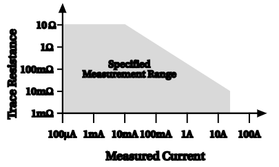
DC IN-CIRCUIT CURRENT
The DC in-circuit current measurement function allows a user to measure the current through a wire or a circuit board trace without breaking the circuit. When the In-Circuit Current Measurement function is selected, the 2001 will first perform a 4-wire resistance measurement, then a voltage measurement, and will display the calculated current.
TYPICAL RANGES:
Current: 100µA to 12A.
Trace Resistance: 1mΩ to 10Ω typical.
Voltage: ±200mV maximum across trace
Speed: 4 measurements/second at 1 power line cycle
Accuracy: ±(5% + 2 counts). For 1 power line cycle, Auto Zero on, 10 reading digital filter, TCAL±5 °C, after being properly zeroed. 90 days, 1 year, or 2 years.
MEASUREMENT RANGE CHART
AC AMPS
AC magnitude: RMS or Average
ACI INPUT CHARACTERISTICS
|
RMS RANGE |
PEAK INPUT |
FULL SCALE RMS |
RESOLUTION |
MAXIMUM BURDEN VOLTAGE46 |
TEMPERATURE COEFFICIENT |
|
200µA |
1mA |
210.0mA |
100pA |
0.25V |
0.01 + 0.001 |
|
2mA |
10mA |
2.10mA |
1nA |
0.31V |
0.01 + 0.001 |
|
20mA |
100mA |
21.0mA |
10nA |
0.4V |
0.01 + 0.001 |
|
200mA |
1A |
210.0A |
100nA |
0.5V |
0.01 + 0.001 |
|
2A |
2A |
2.10A |
1µA |
1.5V |
0.01 + 0.001 |
ACI ACCURACY47, 48
90 days, 1 year or 2 years, TCAL ±5 °C, for 5% to 100% of range, ±(% of reading + % of range)
|
RANGE |
20Hz–50Hz |
50Hz–200Hz |
200Hz–1kHz |
1kHz–10kHz |
10kHz–30kHz10 |
30kHz–50kHz10 |
50kHz–100kHz10 |
|
200µA |
0.35 + 0.015 |
0.2 + 0.015 |
0.4 + 0.015 |
0.5 + 0.015 |
— |
— |
— |
|
2mA |
0.3 + 0.015 |
0.15 + 0.015 |
0.12 + 0.015 |
0.12 + 0.015 |
0.25 + 0.015 |
0.3 + 0.015 |
0.5 + 0.015 |
|
20mA |
0.3 + 0.015 |
0.15 + 0.015 |
0.12 + 0.015 |
0.12 + 0.015 |
0.25 + 0.015 |
0.3 + 0.015 |
0.5 + 0.015 |
|
200mA |
0.3 + 0.015 |
0.15 + 0.015 |
0.12 + 0.015 |
0.15 + 0.015 |
0.5 + 0.015 |
1 + 0.015 |
3 + 0.015 |
|
2A |
0.35 + 0.015 |
0.2 + 0.015 |
0.3 + 0.015 |
0.45 + 0.015 |
1.5 + 0.015 |
4 + 0.015 |
— |
AC CURRENT UNCERTAINTY = ±[ (% of reading) × (measured value) + (% of range) × (range used) ] / 100.
PPM ACCURACY = (% accuracy) × 10,000.
0.015% OF RANGE = 30 counts at 5½ digits.
AC COUPLING
For AC only coupling, add the following % of reading.
|
20Hz to 50Hz |
50Hz to 100Hz |
100Hz to 200kHz |
|
|
RMS, Average |
0.55 |
0.09 |
0.015 |
AC+DC COUPLING
For DC>20% of AC RMS voltage, apply the following additional uncertainty, multiplied by the ratio (DC/AC RMS).
|
% of Reading |
% of Range |
|
|
RMS, Average |
0.05 |
0.1 |
46 Actual maximum voltage burden = (maximum voltage burden) × (IMEASURED/IFULL SCALE).
47 Specifications apply for sine wave input, AC+DC coupling, 1 power line cycle, digital filter off, following 55-minute warm-up.
48 Add 0.005% of range uncertainty for current above 0.5A RMS for self-heating.
ACI READING RATES10, 49
|
NPLC |
MEASUREMENT APERTURE |
BITS |
DEFAULT DIGITS |
READINGS/SECOND TO MEMORY |
READINGS/SECOND TO IEEE-488 |
READINGS/SECOND WITH TIME STAMP TO IEEE-488 |
|||
|
Auto Zero Off |
Auto Zero On |
Auto Zero Off |
Auto Zero On |
Auto Zero Off |
Auto Zero On |
||||
|
10 |
167ms (200ms) |
28 |
6½ |
6 (5.1) |
2 (1.7) |
6 (4.9) |
2 (1.6) |
6 (4.8) |
2 (1.6) |
|
2 |
33.4ms (40ms) |
26 |
5½ |
30 (25) |
9 (7.9) |
28 (23) |
9 (7.6) |
27 (22) |
9 (7.5) |
|
1 |
16.7ms (20ms) |
25 |
5½ |
57 (48) |
39 (35) |
53 (45) |
37 (33) |
49 (41) |
34 (30) |
|
0.1 |
1.67ms (2ms) |
21 |
5½ |
157 (136) |
70 (70) |
123 (123) |
62 (62) |
107 (107) |
56 (53) |
|
0.01 |
167µs (167µs) |
16 |
4½ |
156 (136) |
70 (70) |
140 (140) |
63 (63) |
113 (113) |
56 (56) |
|
0.0111 |
167µs (167µs) |
16 |
4½ |
2000 (2000) |
— |
2000 (2000) |
— |
— |
— |
SETTLING CHARACTERISTICS:
<300ms to 1% of step change
<450ms to 0.1% of step change
<500ms to 0.01% of step change
AUTORANGING: Autoranges up at 105% of range, down at 10% of range.
AVERAGE ACI MEASUREMENT: RMS specifications apply for 10% to 100% of range.
HIGH CREST FACTOR ADDITIONAL ERROR
±(% of reading)
Applies to RMS measurements.
|
CREST FACTOR |
1 – 2 |
2 – 3 |
3 – 4 |
4 – 5 |
|
ADDITIONAL ERROR |
0 |
0.1 |
0.2 |
0.4 |
FREQUENCY COUNTER
FREQUENCY/PERIOD INPUT CHARACTERISTICS AND ACCURACY
90 days, 1 year, or 2 years
|
|
Frequency |
Period |
Resolution |
Minimum Signal Level51 |
Maximum |
Trigger |
Accuracy |
||
|
1Hz–1MHz |
1–5MHz |
5–15MHz |
|||||||
|
AC Voltage Input |
1Hz–15MHz |
67ns – 1s |
5 digits |
60mV |
60mV |
400mV |
1100V pk50 |
0V–600V |
0.03 |
|
AC Current Input |
1Hz – 1MHz |
1µs – 1s |
5 digits |
150µA |
— |
— |
1A pk |
0mA–600mA |
0.03 |
MEASUREMENT TECHNIQUE: Unique pulse count/time count at overflow.
TIME BASE: 7.68MHz ± 0.01%, 0 °C to 55 °C.
READING TIME: 420ms maximum.
TRIGGER LEVEL ADJUSTMENT: Trigger level is adjustable in 0.5% of range steps to ±60% of range in real-time using the up and down range buttons.
FREQUENCY RANGING: Autoranging from Hz to MHz.
FREQUENCY COUPLING: AC only.
49 For DELAY=0, digital filter off, display off, internal trigger. Aperture is reciprocal of line frequency. These rates are for 60Hz and (50Hz).
50 Subject to 2 × 10⁷ V·Hz product (for inputs above 20V).
51 Valid for the lowest range. For each range increase, multiply these numbers by ten. Signals in RMS.
TEMPERATURE (RTD)52
|
RANGE |
RESOLUTION |
4-WIRE ACCURACY53 |
|||
|
1 Hour54 |
90 Days |
1 Year |
2 Years |
||
|
–100° to +100°C |
0.001°C |
±0.005°C |
±0.05°C |
±0.08°C |
±0.12°C |
|
–200° to +630°C |
0.001°C |
±0.005°C |
±0.12°C |
±0.14°C |
±0.18°C |
|
–212° to +180°F |
0.001°F |
±0.009°F |
±0.09°F |
±0.15°F |
±0.22°F |
|
–360° to +1102°F |
0.001°F |
±0.009°F |
±0.15°F |
±0.18°F |
±0.33°F |
RTD TYPE: 100Ω platinum; DIN 43 760 or IPTS-68, alpha 0.00385, 0.00390, 0.003916, or 0.00392, 4-wire.
MAXIMUM LEAD RESISTANCE (each lead): 12 Ω (to achieve rated accuracy).
SENSOR CURRENT: 1 mA (pulsed).
COMMON MODE REJECTION: <0.005 °C/V at DC, 50 Hz, 60 Hz and 400 Hz, (100 Ω imbalance, LO driven).
TEMPERATURE COEFFICIENT: ±(0.0013% + 0.005 °C)/°C or ±(0.0013% + 0.01 °F)/°C outside TCAL ±5 °C.
RTD TEMPERATURE READING RATES55 (2-WIRE OR 4-WIRE)
|
NPLC |
READINGS or READINGS WITH TIME STAMP/SECOND |
|
|
Autozero Off |
Autozero On |
|
|
10 |
1 (1) |
1 (1) |
|
2 |
5 (4.3) |
4 (3.6) |
|
1 |
7 (6.5) |
6 (5.5) |
|
0.1 |
12 (10.8) |
9 (9) |
|
0.01 |
12 (12) |
10 (10) |
TEMPERATURE (THERMOCOUPLE)
|
Thermocouple Type |
Range |
Default Resolution |
Accuracy56 |
|
J |
–200° to +760°C |
0.1°C |
±0.5°C |
|
K |
–200° to +1372°C |
0.1°C |
±0.5°C |
|
T |
–200° to +400°C |
0.1°C |
±0.5°C |
|
E |
–200° to +1000°C |
0.1°C |
±0.6°C |
|
R |
0° to +1768°C |
1°C |
±3°C |
|
S |
0° to +1768°C |
1°C |
±3°C |
|
B |
+350° to +1820°C |
1°C |
±5°C |
52 Accuracy for all thermocouple types and the 100 Ω platinum, D100, and F100 RTD types based on ITS-90. Accuracy for the PT385 and PT3916 RTD types based on IPTS-68.
53 Excluding probe errors. TCAL ±5 °C.
54 For ambient temperature ±1 °C, measured temperature ±10 °C, 10-reading digital filter
55 Typical speeds for Auto Zero on. For DELAY=0, digital filter off, display off, internal trigger. Rates are for 60 Hz and (50 Hz).
56 Relative to external 0 °C reference junction; exclusive of thermocouple errors. Junction temperature may be external. Applies for 90 days, 1 year or 2 years, TCAL ±5 °C.
TC TEMPERATURE READING RATES55
|
NPLC |
READINGS/SECOND TO MEMORY |
READINGS/SECOND TO IEEE-488 |
READINGS/SECOND WITH |
|||
|
Off |
On |
Off |
On |
Off |
On |
|
|
10 |
6 (5.1) |
2 (1.7) |
4 (3.4) |
2 (1.4) |
4 (3.4) |
2 (1.4) |
|
2 |
30 (25) |
9 (7.6) |
28 (23) |
9 (7.3) |
27 (22) |
8 (7.2) |
|
1 |
57 (48) |
43 (37) |
53 (45) |
40 (32) |
49 (41) |
37 (30) |
|
0.1 |
139 (139) |
95 (95) |
126 (123) |
85 (84) |
99 (99) |
72 (72) |
|
0.01 |
177 (177) |
98 (98) |
156 (156) |
87 (87) |
119 (119) |
73 (73) |
OPERATING SPEED
The following diagram illustrates the factors that determine a DMM's reading rate.

COMMAND RECEIVE AND INTERPRET SPEED
|
|
FASTEST |
TYPICAL |
SLOWEST |
|
Time per character |
0.16ms |
0.28ms |
0.66ms |
|
Characters per second |
6250 |
3751 |
1515 |
TYPICAL COMMAND TIMES
|
COMMAND |
RECEIVE AND INTERPRET TIME |
RATE |
|
SENSE1:VOLTAGE:AC: |
9.4ms |
106 |
|
VOLT:AC:RES:MAX |
4.1ms |
243 |
|
SENSE1:FUNC "VOLT:AC" |
6.3ms |
158 |
|
RESISTANCE:RANGE:UPPER 1E9 |
9.0ms |
111 |
|
STATUS:QUEUE:CLEAR |
5.1ms |
196 |
|
STAT:QUE:CLE |
3.1ms |
322 |
|
*TRG |
1.2ms |
833 |
MEASUREMENT SPEED CHANGE TIMES57, 58
Typical delay before first reading after making a speed change.
|
FUNCTION |
From |
To |
AUTO ZERO OFF |
AUTO ZERO ON |
|
DCV, DCI, ACI |
Any |
≤0.1 PLC |
66ms |
44ms |
|
Any |
1 PLC |
190ms |
140ms |
|
|
Any |
10 PLC |
1540ms |
1195ms |
|
|
ACV |
Any |
≤0.1 PLC |
120ms |
100ms |
|
Any |
1 PLC |
250ms |
197ms |
|
|
Any |
10 PLC |
1600ms |
1250ms |
|
|
Ohms (2-wire) |
Any |
≤0.1 PLC |
69ms |
57ms |
|
Any |
1 PLC |
195ms |
170ms |
|
|
Any |
10 PLC |
1540ms |
1370ms |
|
|
Ohms (4-wire) |
Any |
≤0.1 PLC |
110ms |
46ms |
|
Any |
1 PLC |
240ms |
165ms |
|
|
Any |
10 PLC |
1590ms |
1370ms |
|
|
TC Temperature |
Any |
≤0.1 PLC |
80ms |
55ms |
|
Any |
1 PLC |
195ms |
170ms |
|
|
Any |
10 PLC |
1545ms |
1370ms |
57 With display off, 1 power line cycle, autorange off, filter off, triggers halted. Display on may impact time by 3% worst case. To eliminate this impact, press ENTER (hold) to lock out display from front panel.
58 Based on using 20V, 2kΩ, 200mA ranges.
FUNCTION CHANGE SPEED57
|
FROM Function |
TO Function |
RANGES |
AUTO ZERO OFF |
AUTO ZERO ON |
||
|
TIME |
RATE |
TIME |
RATE |
|||
|
Any |
DCV |
200mV, 2V |
8.1ms |
120 |
36ms |
27 |
|
Any |
ACV |
Any |
563ms |
1.8 |
563ms |
1.8 |
|
Any except ACI |
DCI |
200µA, 2mA, 20mA |
4.5ms |
220 |
5.1ms |
190 |
|
Any |
ACI |
Any |
521ms |
1.9 |
521ms |
1.9 |
|
Any |
Ohms (2-wire) |
20Ω, 200Ω, 2kΩ, 20kΩ |
6.0ms |
165 |
34ms |
29 |
|
Any |
Ohms (4-wire) |
20Ω, 200Ω, 2kΩ, 20kΩ |
12ms |
140 |
34.1ms |
29 |
|
Any except ACI and Ohms |
Frequency59 |
Any |
61ms |
16 |
60ms |
17 |
|
Any |
RTD Temp. (2-wire) |
Any |
6.0ms |
165 |
33ms |
30 |
RANGE CHANGE SPEED57
|
FUNCTION |
From |
To |
AUTO ZERO OFF |
AUTO ZERO ON |
||
|
TIME |
RATE |
TIME |
RATE |
|||
|
DCV |
200mV, 2V |
20V |
4.5ms |
220 |
3.1ms |
190 |
|
ACV |
Any |
Any |
563ms |
1.8 |
563ms |
1.8 |
|
DCI |
Any |
200µA, 2mA, 20mA |
4.5ms |
220 |
5.2ms |
190 |
|
ACI |
Any |
Any |
525ms |
1.9 |
525ms |
1.9 |
|
Ohms (2-wire) |
Any |
20Ω, 200Ω, 2kΩ, 20kΩ |
6.0ms |
160 |
34ms |
29 |
|
Ohms (4-wire) |
Any |
20Ω, 200Ω, 2kΩ, 20kΩ |
8ms |
160 |
34ms |
29 |
59 Based on 100kHz input frequency.
TRIGGER SPEED (EXTERNAL TRIGGER OR TRIGGER-LINK)
|
|
Autozero On |
Autozero Off |
|
Trigger Latency |
1.2 ms typical |
2µs |
|
Trigger Jitter |
— |
±0.5µs |
ENGINEERING UNIT CONVERSION SPEED
Included in reading times for multiple measurements; add to total time for single measurements only.
|
CONFIGURATION |
TIME |
RATE (per second) |
|
DCV |
2.4ms |
416 |
|
DCV, Filter on |
2.4ms |
416 |
|
DCV, Relative on |
2.5ms |
400 |
|
DCV, Ratio on |
3.7ms |
270 |
|
ACV |
5.3ms |
188 |
|
ACV, Relative on |
5.3ms |
188 |
|
ACV, Filter on |
6.8ms |
147 |
|
ACV, dB |
9.4ms |
106 |
|
ACV, dBm |
17.3ms |
57 |
DISPLAY SPEED
Display updated 20 times per second. Display update can be suspended by holding the display (press ENTER) or setting Display Enable Off from GPIB.
MATH AND LIMITS CALCULATION SPEED57
|
CALCULATION |
NOMINAL TIME |
NOMINAL RATE (per second) |
MAXIMUM TIME |
|
mx + b |
0.35ms |
2850 |
0.44ms |
|
Percent |
0.60ms |
1660 |
0.64ms |
|
Limits60 |
0.35ms |
2850 |
0.37ms |
|
None |
0.07ms |
— |
0.08ms |
GPIB DATA FORMATTING TRANSMISSION TIME61
|
FORMAT |
READINGS ONLY |
READINGS WITH TIME STAMP |
||
|
Time |
Readings/s |
Time |
Reading/s |
|
|
DREAL |
0.30ms |
3330 |
2.0ms |
500 |
|
SREAL |
0.37ms |
2710 |
2.1ms |
475 |
|
ASCII |
3.9ms |
255 |
8.2ms |
120 |
60 Time to measure, evaluate limits, and set digital outputs are found by summing measurement time with limits calculation time
61 Auto Zero off, using 386SX/16 computer, average time for 1000 readings, byte order swapped, front panel disabled.
SINGLE FUNCTION SCAN SPEED62 (internal scanner)
|
TYPE |
DCV (20V)63 |
2-Wire Ohms |
4-Wire Ohms |
ACV |
Frequency |
TC Temperature |
RTD Temperature |
|||||||
|
Time |
Rate |
Time |
Rate |
Time |
Rate |
Time |
Rate |
Time |
Rate |
Time |
Rate |
Time |
Rate |
|
|
Ratio or Delta64
|
4ms |
250 |
4.4ms |
230 |
18.5ms |
54 |
— |
— |
— |
— |
— |
— |
— |
— |
|
Fast Scan |
5.5ms |
181 |
7ms |
140 |
— |
— |
520ms |
1.9 |
958ms |
1 |
13.8ms |
72 |
— |
— |
|
Normal Scan |
10.3ms |
97 |
12.1ms |
80 |
21ms |
47 |
532ms |
1.8 |
974ms |
1 |
18ms |
55 |
95ms |
10 |
MIXED FUNCTION SCAN SPEED57 (internal scanner)
|
SCAN CONFIGURATION |
Average Time/Channel |
Average Rate(Channel/s) |
|
5 chan. DCV, 5 chan, 2wΩ |
20ms |
50 |
|
3 DCV, 3 2wΩ, 4 TC |
22ms |
45 |
|
5 2wRTD, 5 TC |
60ms |
17 |
|
5 2wΩ, 5 2wRTD |
60ms |
17 |
|
9 DCV, 1 ACV |
73ms |
13 |
|
2 DCV 1, ACV, 2 2wΩ, 1 4wΩ |
122ms |
8 |
|
5 DCV, 5 Freq. |
490ms |
2 |
|
3 DCV, 3 ACV, 2 4wΩ |
220ms |
5 |
DELAY AND TIMER
| TIME STAMP | Resolution: 1µs. Accuracy: ±0.01% ± 1µs. Maximum: 2,100,000.000 000 seconds (24 days, 20 hours). |
| DELAY TIME | (Trigger edge to reading initiation) Maximum: 999,999.999 seconds (11 days, 12 hours). Resolution: 1ms. Jitter: ±1ms. |
| TIMER | (Reading initiation to reading initiation) Maximum: 999,999.999 seconds (11 days, 12 hours). Resolution: 1ms. Jitter: ±1ms. |
NOTE: To find measurement speed, see each measurement section.
62 Typical times for 0.01 power line cycle, autoranging off, Delay=0, 100 measurements into buffer.
63 Auto Zero off.
64 Ratio and delta functions output one value for each pair of measurements.
MAXIMUM INPUT LEVELS
|
|
Rated Input65 |
Overload Recovery Time |
|
HI to LO |
±1100V pk |
< 900ms |
|
HI Sense to LO |
± 350V pk 250V RMS |
< 900ms |
|
LO Sense to LO |
± 350V pk 250V RMS |
< 900ms |
|
AMPS Input to LO |
2A, ± 250V (fused) |
— |
|
HI to Earth |
±1600V |
< 900ms |
|
LO to Earth |
±500V |
— |
IEEE-488 BUS IMPLEMENTATION
IMPLEMENTATION: IEEE-488.2, SCPI-1991.0.
MULTILINE COMMANDS: DCL, LLO, SDC, GET, GTL, UNT, UNL, SPE, SPD.
UNILINE COMMANDS: IFC, REN, EOI, SRQ, ATN.
INTERFACE COMMANDS: SH1, AH1, T5, TE0, L4, LE0, SR1, RL1, PP0, DC1, DT1, C0, E1.
DIGITAL I/O
CONNECTOR TYPE: 8 pin "D" subminiature.
INPUT: One pin, TTL compatible.
OUTPUTS: Four pins. Open collector, 30V maximum pull-up voltage, 100mA maximum sink current, 10Ω output impedance.
CONTROL: Direct control by output or set real-time with limits.
65 For voltages between other terminals, these ratings can be algebraically added.
GENERAL SPECIFICATIONS AND STANDARDS COMPLIANCE
| POWER | Voltage: 90V to 134V and 180V to 250V, universal self-selecting. Frequency: 50Hz, 60Hz, or 400Hz, self-identifying. Consumption: <55VA. |
| ENVIRONMENTAL | Operating Temperature: 0 °C to 50 °C. Storage Temperature: −40 °C to 70 °C. Humidity: 80% R.H., 0 °C to 35 °C, per MIL-T-28800E66 Para 4.5.5.1.2 |
| NORMAL CALIBRATION | Type: Software. No manual adjustments required. Sources: 2 DC voltages (2V, 20V) and 2 resistances (19k and 1M). Different calibration source values are allowed. All other functions calibrated (adjusted) from these sources and a short circuit. No AC calibrator required for adjustment. |
| PHYSICAL | Case Dimensions: 90mm high × 214mm wide × 369mm deep (3½ in. × 8½ in. × 14½ in.). Working Dimensions: From front of case to rear including power cord and IEEE-488 connector: 15.0 inches. Net Weight: <4.2kg (<9.2 lb). Shipping Weight: <9.1kg (<20 lb). |
| STANDARDS | EMI/RFI: Conforms to VDE 0871B (per Vfg 1046/1984), IEC 801-2. Meets FCC part 15 Class B, CISPR-22 (EN55022). Safety: Conforms to IEC348, CAN/CSA-C22.2. No. 231, MIL-T-28800E66. Designed to UL1244. Reliability: MIL-T-28800E66. Maintainability: MIL-T-28800E66. Mean time to repair (MTTR): <90 minutes (includes disassembly and assembly, excludes recalibration). Mean time between failure (MTBF), estimated: >75,000 hours (Bellcore method). Mean time to calibrate (MTTC): <20 minutes for normal calibration. <6 minutes for AC self-calibration. Process: MIL-STD 45662A and BS5750. |
EXTENDED MEMORY/NONVOLATILE MEMORY OPTIONS
DATA STORAGE
|
Model |
Size (Bytes) |
4½-Digit |
6½-Digit |
Type |
Setup Storage |
|
|
Number |
Type |
|||||
|
2001 |
8k |
2,027 |
404 |
volatile |
1 |
nonvolatile |
|
2001/MEM1 |
32k |
6,909 |
1,381 |
nonvolatile |
5 |
nonvolatile |
|
2001/MEM2 |
128k |
29,908 |
5,980 |
nonvolatile |
10 |
nonvolatile |
These are the minimum sizes to expect.
66 For MIL-T-28800E, applies to Type III, Class 5, Style E.