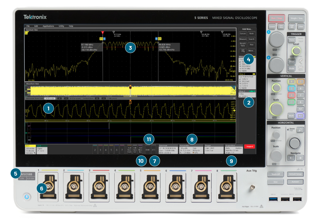
1) User interface designed for both touch and mouse
2) Large touchscreen HD displays (1,920 × 1,080)
3) Integrated spectrum analysis
4) Powerful analysis
- Automated measurements with trend, histogram, and spectrum plots
- Advanced jitter analysis
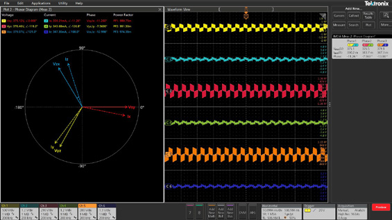
- Single-phase and 3-phase power measurement options
- User-defined filter creation
5) Bandwidth
- Models from 100 MHz to 10 GHz
- All models offer upgradeable bandwidth
6) Input channels
- 2 to 8 inputs depending on model
- Low-loading probes included for each channel
7) Built in Arbitrary/Function Generator option
8) Record length
- 10 Mpoints to 1 Gpoints depending on model
9) Up to 12-bit vertical resolution (up to 16 bits in High Res mode)
10) Protocol options
- 1-Wire
- 8b10b
- Automotive Ethernet
- CAN / CAN FD
- CXPI
- eSPI
- Ethernet
- EtherCAT
- eUSB2
- FlexRay
- I2C / SPI
- I2S Audio
- I3C
- LIN
- Manchester
- MDIO
- MIL-STD-1533 / ARINC 429
- MIPI CSI/DSI
- NFC
- NRZ
- PSI5
- RS-232 / UART
- SDLC
- SENT
- SMBus
- SpaceWire
- SPMI
- SVID
- USB 2.0
11) Integrated DVM and trigger frequency counter free with product registration
Usability and Display
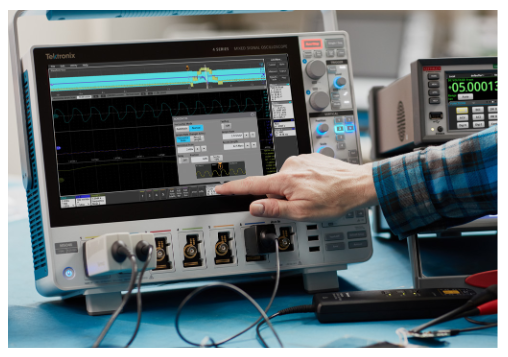
Touch Interaction Done Right
These next-generation oscilloscopes feature the industry’s first oscilloscope user interface truly designed for touch. The same intuitive gestures you use with your phone or tablet work on the big HD displays and the gestures are common among the 3, 4, 5 and 6 Series.
- Control inputs, triggers and acquisitions by tapping badges in the settings bar at the bottom of the display
- Drag waveforms to adjust position or to pan
- Pinch to change horizontal or vertical scale

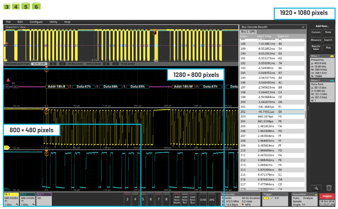
Stunning HD Displays
The 15.6" displays on 5 and 6 Series MSOs have 1920 × 1080 HD resolution. You can see many signals at once, along with critical readouts and plots for an extensive view of your system.
Even with their bench-friendly footprints, the 3 and 4 Series offer the largest displays in their classes, with full 1920 × 1080 HD resolution.
Performance and Measurements
More Inputs and Mixed Signal Analysis
The 4, 5 and 6 Series MSOs let you see more signals by going beyond the traditional 4-channel limit, offering up to 8 analog input channels.
FlexChannel™ inputs on the 4, 5, and 6 Series MSOs expand your visibility even further. Whenever you need to see more signals, just plug a TLP058 logic probe into any input. The single analog channel converts to 8 digital channels. FlexChannel inputs are compatible with TekVPI probes.
The 3 Series MDO offers 16 digital channels through a dedicated logic probe, included with the MSO option.
Industry-leading Vertical Resolution
See more signal detail. The 4, 5, and 6 Series MSOs feature 12-bit analog-to-digital converters (ADCs) that provide 16 times more vertical resolution than common 8-bit ADCs.
A new High Res mode further boosts vertical resolution and uses smart filtering to limit noise. High Res mode always provides at least 12 bits and extends all the way to 16 bits of vertical resolution.

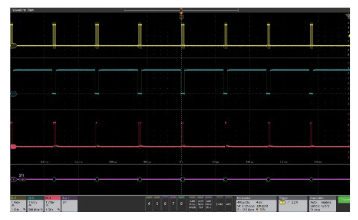
Stacked Display Mode
Most scopes display all waveforms in the same graticule and rely on vertical scale controls to fit signals on the display. Each waveform uses a fraction of the available ADC range, leading to less accurate measurements.
New stacked display mode lets you view each waveform in its own "slice" of the display. Each slice represents the full ADC range for the waveform for more accurate measurements.
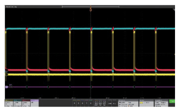
The more traditional overlay display mode is also available, for easy direct comparison of waveforms.
Powerful Measurements
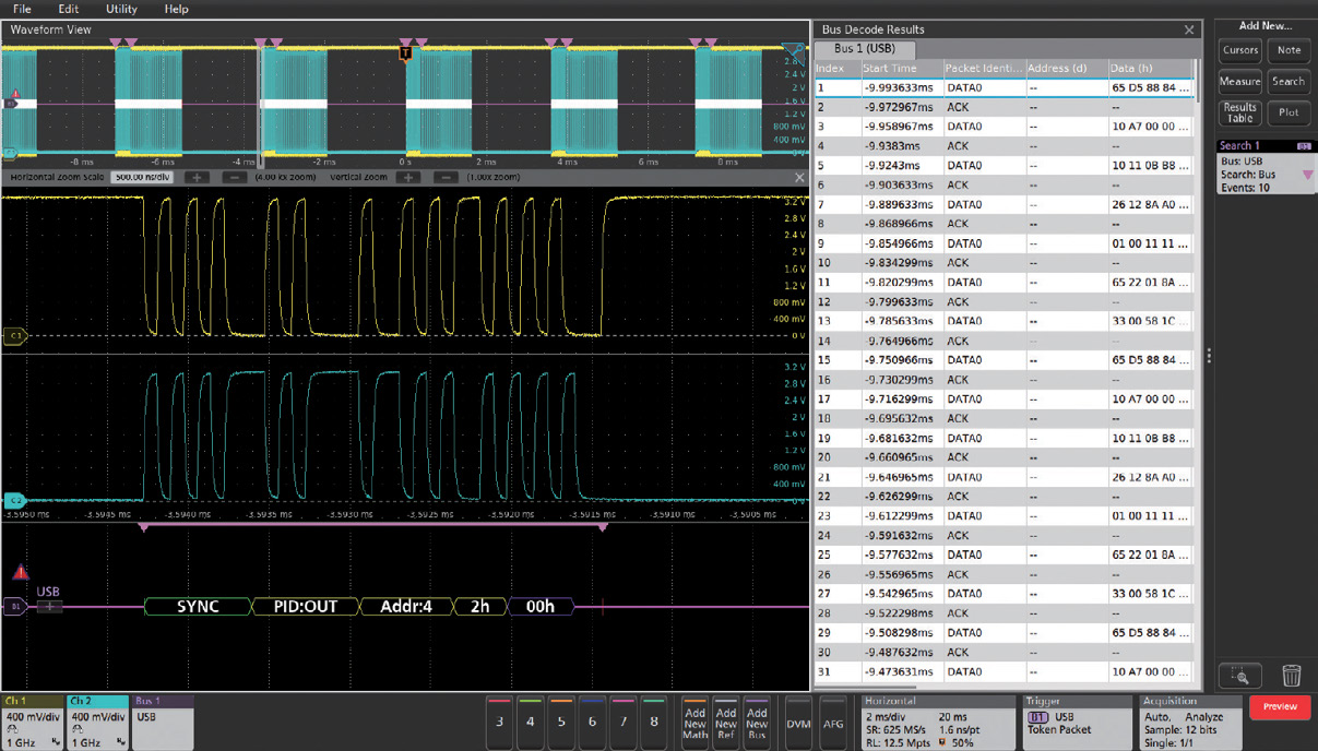
The Results Bar on the right side of the display includes immediate, one-tap access to the most common analytical tools such as:
- Cursors
- Automated measurements
- Measurement statistics
- Searches
- Bus decode tables
Gain rich insights with easy access to measurement statistics. Turn on statistics in the Results Bar to get a quick overview.
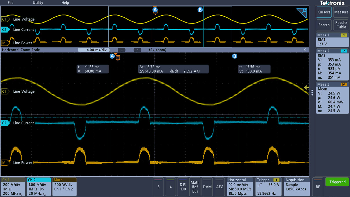
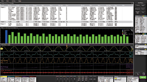
Advanced Measurements and Analysis
Dive into measurements with Results Tables. Results Tables show statistics for the current acquisition and for all acquisitions. Get insight into one measurement, a hundred measurements, or millions of measurements at a glance.
Plots, such as measurement trends and histograms, provide quick visualizations.

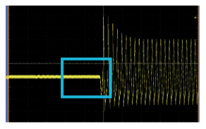
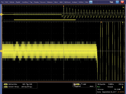
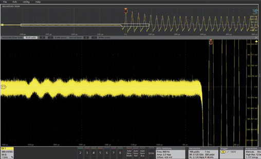
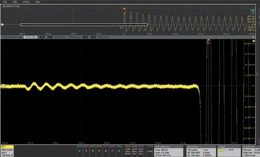
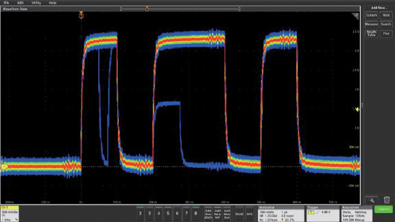
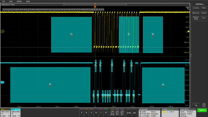
FastAcq™ High Speed Waveform Capture
FastAcq captures at high speed to increase the probability of seeing infrequent problems such as runt pulses, glitches, timing issues, and more.
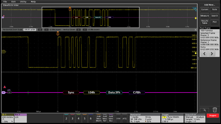
FastFrame™ Segmented Memory and History Mode
Make the most efficient use of acquisition memory by not storing deadtime between serial packets or bursts. Capture many triggered frames in a single record.
Triggering and Search
A complete set of basic and advanced triggers and search criteria.
- Runt
- Logic
- Pulse width
- Timeout
- Rise/Fall time
- Setup and hold violations
- Serial and parallel bus activity
- Sequence
- Video
- Visual triggers*
- RF vs Time*
- Window*
*4, 5, 6 Series only
An Oscilloscope for Every Engineer
 |
 |
 |
 |
|
| Bandwidth | 100 MHz, 200 MHz,350 MHz, 500 MHz, 1 GHz | 200 MHz, 350 MHz,500 MHz, 1 GHz, 1.5 GHz | 350 MHz, 500 MHz,1 GHz, 2 GHz | 1 GHz, 2.5 GHz, 4 GHz,6 GHz, 8 GHz, 10 GHz |
| Max channels, analog | 4 | 6 | 8 | 8 |
| Max channels, digital | 16 | 48 | 64 | 64 |
| Inputs | TekVPI inputs | FlexChannel inputs | FlexChannel inputs | FlexChannel inputs |
| Max sample rate | 2.5 GS/s or 5 GS/s, all channels | 6.25 GS/s, all channels | 6.25 GS/s, all channels | 50 GS/s, 2 channels |
| Record length | 10 Mpoints | Up to 62.5 Mpoints | Up to 500 Mpoints | Up to 1 Gpoints |
| Vertical resolution | 8 bits | 12 bits | 12 bits | 12 bits |
| Advanced analysis(optional) | Serial bus, Power | Serial bus, Power, 3-Phase Power | Serial bus, Power, Compliance, Jitter, Inverters, Motors and Drives | Serial bus, Power, Compliance, Jitter, Inverters, Motors and Drives, DDR3, LVDS |
| Spectrum analysis | Hardware Spectrum Analyzer | Spectrum View | Spectrum View | Spectrum View |
| Operating system | Embedded | Embedded | Embedded Windows (optional) |
Embedded Windows (optional) |
| Display | 11.6" HD, capacitive touch 1920 × 1080 | 13.3" HD, capacitive touch 1920 × 1080 | 15.6" HD, capacitive touch 1920 × 1080 | 15.6" HD, capacitive touch 1920 × 1080 |
| Starting price | $4,510 USD | $9,000 USD | $19,100 USD | $34,700 USD |
Pricing shown in US currency and is subject to change. Please check respective product series pages for the most up to date pricing by model.
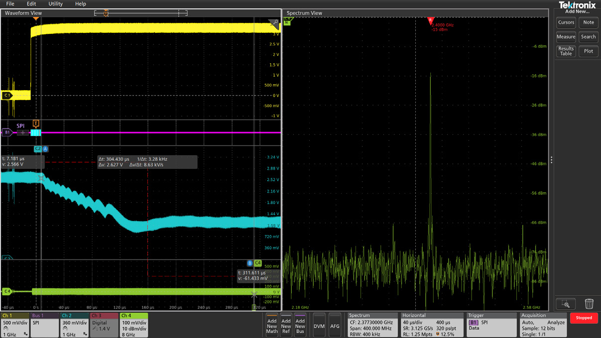
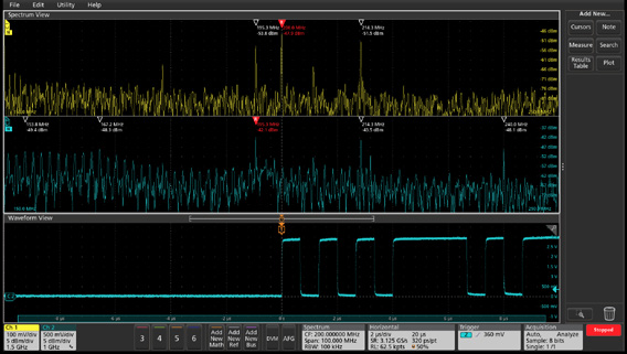
Integrated Spectrum Analysis
Spectrum View
Because traditional scope FFTs are driven by the same acquisition system that delivers the analog time-domain view, it is virtually impossible to get optimized views in both domains at once.
Spectrum View is different. It lets you independently adjust time and frequency-domain views, by using patented technology behind each FlexChannel input. You can turn on a spectrum view for any analog channel, enabling multi-channel mixed domain analysis.
Intuitive spectrum analyzer controls like center frequency, span and resolution bandwidth (RBW) make setups easy, and RF vs time triggers make capturing anomalies straightforward.
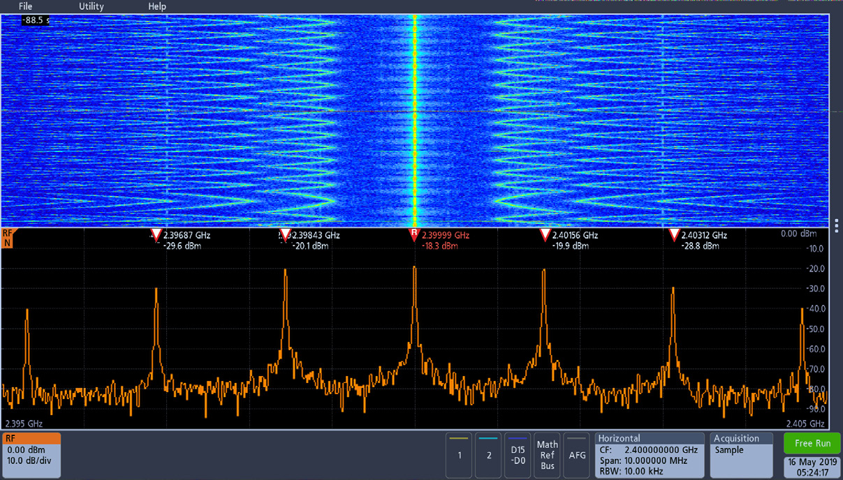
Built-in Spectrum Analyzer
The Tektronix 3 Series MDO offers an integrated, hardware-based spectrum analyzer ranging from 9 kHz to 1 GHz (standard) or 3 GHz enabling spectral analysis on IoT and most consumer wireless standards.

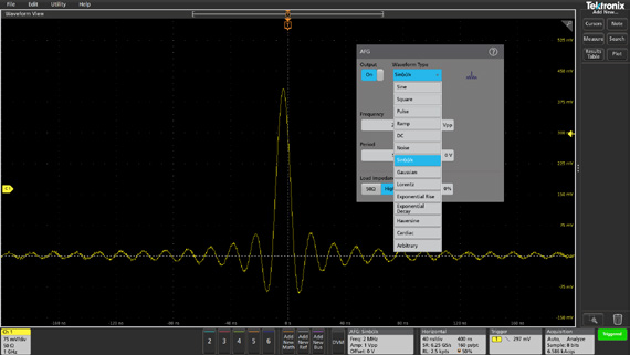
Built-in Arbitrary/Function Generator (AFG)
An integrated function generator is perfect for testing frequency response, simulating sensor signals, and adding noise to signals for stress testing.
- 13 standard waveform functions
- 50 MHz Sine / 25 MHz Square and Pulse (100 MHz Sine / 50 MHz Square and Pulse on 5 Series B MSO)
- 128k, 250 MS/s arbitrary waveforms
Connectivity
Every instrument includes a USB device port and LXI-compliant Ethernet port for remote control. A thoroughly documented programming interface supports custom programming.
With e*Scope built-in, you can control the oscilloscope over a network using only a standard web browser.
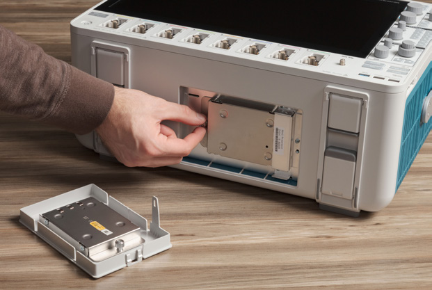
Optional Windows OS
The 5 and 6 Series MSOs offer the option of including a Microsoft Windows™ operating system. The option provides a Windows desktop where you can install and run additional applications on the oscilloscope.
Upgrading to Windows is as simple as plugging in a pre-configured SSD.

Applications and Advanced Analysis.Emphasis on Analysis.
Built-in features, available probes, and optional analysis packages support a wide range of applications.
SignalVu-PC Vector Signal Analysis
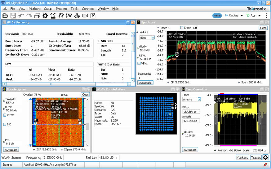
SignalVu-PC turns your Windows-equipped 5 or 6 Series MSO into a wideband vector signal analyzer. It can be customized to suit your appplication.
- Perform multi-channel RF measurements
- Demodulate and analyze RF signals
- Validate radar or pulsed RF
- Measure 5G NR signals
Advanced Analysis
Software
TekScope PC Analysis Software
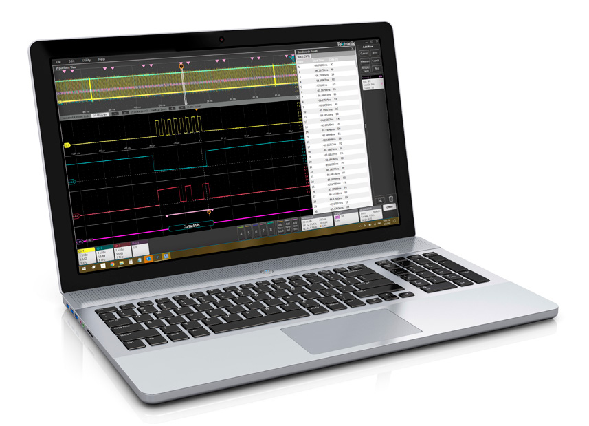
TekScope emulates the operation of a 4, 5 or 6 Series on your PC.The starter license enables you to view and analyze waveforms, make measurements, remotely access your oscilloscope, and decode I2C, SPI and RS-232.
Advanced licenses add:
- Multi-scope waveform processing (4/5/6 Series)
- Serial bus decoding
- Power analysis
- Automotive Measurements
- Aerospace Measurements
TekDrive
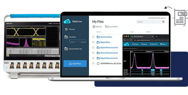
An oscilloscope-to-cloud software solution that facilitates data management and collaboration across oscilloscopes, PCs, smart phones, and tablets. On 4, 5 and 6 Series MSOs, TekDrive is accessible right from the Save/Recall controls. TekDrive also includes a well-documented API that enables integration with any software application for automation or analysis.
Probes
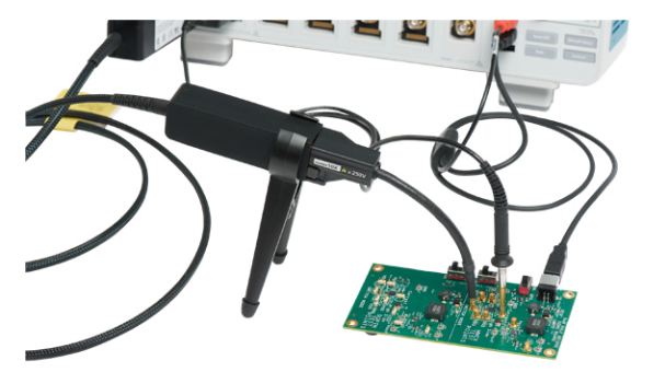
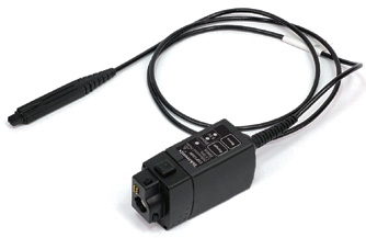
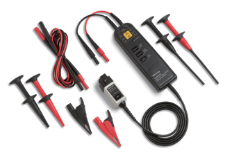
IsoVu™ Isolated Probes
IsoVu™ optical isolation technology virtually eliminates common mode interference for accurate differential measurements even with reference voltages slewing ±60 kV at 100 V/ns. Perfect for highside VGS measurements on GaN and SiC power converters.
| TIVP Series Specifications | |
| Bandwidth | 200 MHz, 500 MHz, 1 GHz |
| Differential Voltage | ±2500 V |
| Common Mode Voltage | ±60 kV |
| Common Mode Rejection | 100 dB @ 200 MHz |
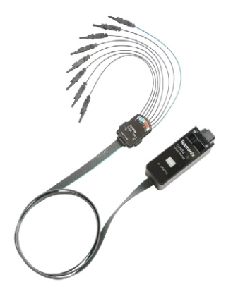
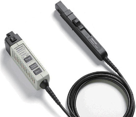
TLP058 Logic Probes
Have the right number of digital channels when you need them.Simply connect a TLP058 logic probe to any FlexChannel input and get 8 digital channels. Connect as many TLP058 probes you want.
| TLP058 Specifications | |
| Number Of Input Channels | 8 digital |
| Input Resistance | 100 kΩ±1.0% |
| Input Capacitance | 3.0pF |
| Min. Detectable Pulse Width | 1ns |
| Max. Input Toggle Rate | 500 MHz |
| Cable Length | 1.0m |
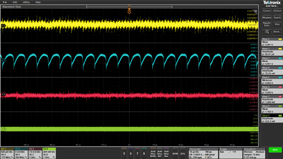
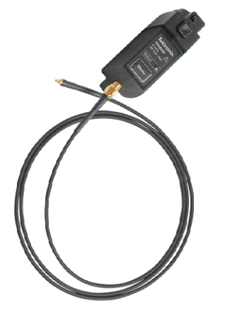
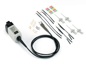
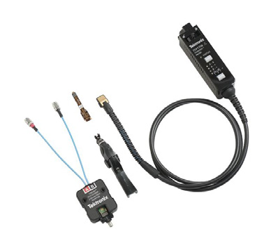
Power Rail Probes
Probes designed especially for making accurate ripple measurements on power rails, with ± 60 V DC offset range, low noise contribution and bandwidth up to 4 GHz.
| TPR1000/TPR4000 Specifications | |
| Bandwidth | TPR1000: 1 GHz TPR4000: 4 GHz |
| Attenuation | 1.25X |
| Input impedance | 50 kΩ DC - 10 kHz, 50 Ω AC > 100 kHz |
| Dynamic range | ±1 V |
| Offset range | ±60 V |
For complete list of available probes visit tek.com/probes
Passive Probes
| Model | Bandwidth | Attenuation | Input Impedance | Maximum Voltage |
| TPP1000 | 1 GHz | 10X | 10 MΩ || 3.9 pF | 300 Vrms (CAT II) |
| TPP0500B | 500 MHz | 10X | 10 MΩ || 3.9 pF | 300 Vrms (CAT II) |
| TPP0502 | 500 GHz | 2X | 2 MΩ || 12.7 pF | 300 Vrms (CAT II) |
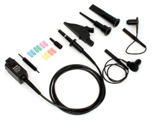
Active Probes
| Model | Bandwidth | Attenuation | Input Impedance | Dynamic Range | Offset Range | Maximum Non-Destruct Voltage |
| TAP1500 | 1.5 GHz | 10X | 1 MΩ || ≤ 1 pF | ±8 V | ±10 V | ±15 V |
| TAP2500 | 2.5 GHz | 10X | 40 kΩ || ≤ 0.8 pF | ±4 V | ±10 V | ±30 V |
Differential Probes
| Model | Bandwidth | Rise Time | Attenuation | Differential Operating Voltage | Ground Operating Voltage | Input resistance/Input capacitance |
| TDP0500 | 500 MHz | ≤700ps | 5X / 50X | ±4.25 V (5X) ±42 V (50X) |
±35 V | 1MΩ/1pF differential |
| TDP1000 | 1 GHz | ≤350ps | 5X / 50X | ±4.25 V (5X) ±42 V (50X) |
±35 V | 1MΩ/1pF differential |
| TDP1500 | 1.5 GHz | ≤265ps | 1X / 10X | ±0.85 V (1X) ±8.5 V (10X) |
±7.0 V | 200KΩ/1pF differential |
| TDP3500 | 3.5 GHz | ≤140ps | 5X | ±2 V | + 5 to -4 V | 100KΩ/0.3pF differential |
| TDP4000 | 4.0 GHz | ≤126ps | 5X | ±2 V | + 5 to -4 V | 100KΩ/0.3pF differential |
High Voltage Probes
| Model | Bandwidth | Max Voltage | Attenuation | Input Impedance | Compensation Range |
| P6015A | 75 MHz | 20 kVrms 40 kV peak |
1000X | 100 MΩ || ≤ 3 pF | 7 pF – 49 pF |
| TPP0850 | 800 MHz | 1000 Vrms (CAT II) 2.5 kV peak |
50X | 40 MΩ || 1.8 pF | Auto compensated by scope |
High Voltage Differential Probes
| Model | Bandwidth | Rise Time | Attenuation | Maximum Differential Voltage | Maximum Voltage to Earth Ground | Differential Input Capacitance | Differential Input Resistance |
| TMDP0200 | 200 MHz | 1.8 ns | 25X / 250X | ±750 V | 550 Vrms (CAT I) | 2 pF | 5 MΩ |
| THDP0200 | 200 MHz | 1.8 ns | 50X / 500X | ±1500 V | 1000 Vrms (CAT II) | 2 pF | 10 MΩ |
| THDP0100 | 100 MHz | 3.5 ns | 100X / 1000X | ±6000 V | 2300 Vrms (CAT I) | 2.5 pF | 40 MΩ |
Current Probes
| Model | Maximum Current | Minimum Current | Bandwidth | Rise Time |
| TCP0030A | 30 A DC; 30 Arms; 50 A peak | 1 mA | DC - 120 MHz | ≤ 2.92 ns |
| TCP0020 | 20 A DC; 20 Arms; 100 A peak | 10 mA | DC - 50 MHz | ≤ 7 ns |
| TCP0150 | 150 A DC; 150 Arms; 500 A peak | 5 mA | DC - 20 MHz | ≤ 17.5 ns |
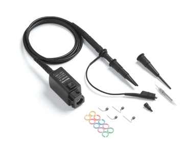
High Bandwidth Differential Probes
| Model | Bandwidth |
| TDP7704 | 4 GHz |
| TDP7706 | 6 GHz |
| TDP7708 | 8 GHz |
| TDP7710 | 10 GHz |
| Tekflex Accessory | Attenuation | Input Impedance | Differential Input Voltage | Operating Window | Offset Range |
| P77STFLXA,P77STLFXB,P77STCABL | 4X | 100 kΩ || 0.4 pF | 5V | ±5.25 V | ±4 V |
| P77BRWSR | 10X | 150 kΩ || 22 pF | 12V | ±10 V | ±10 V |
| P77C292MM | Variable | 50 Ω (SMA) | 2V | ±4 V | ±4 V |
Models and Instrument Options
For complete ordering details see the product datasheet or contact your local sales representative.
| Base Models | 3 Series MDO | 4 Series B MSO | 5 Series B MSO | 6 Series B MSO | |
| Instrument Options | 2 TekVPI Channels | MDO32 | |||
| 4 TekVPI Channels | MDO34 | ||||
| 4 FlexChannel Inputs | MSO44B | MSO54B | MSO64B | ||
| 6 FlexChannel Inputs | MSO46B | MSO56B | MSO66B | ||
| 8 FlexChannel Inputs | MSO58B | MSO68B | |||
| Bandwidth | 100 MHz, 200 MHz, 350 MHz, 500 MHz, 1 GHz | 200 MHz, 350 MHz, 500 MHz,1 GHz, 1.5 GHz | 350 MHz, 500 MHz, 1 GHz, 2 GHz | 1 GHz, 2.5 GHz, 4 GHz, 6 GHz, 8 GHz, 10 GHz | |
| Digital Channels | • | simply order TLP058 probes to enable 8 digital signals per probe | |||
| Arbitrary Function Generator | • | • | • | • | |
| Spectrum Analyzer | 1 GHz (std.), 3 GHz | see Spectrum View analysis | |||
| Extend Record Length | (10 M standard) | 62.5 M/ch max (31.25 M standard) |
125 M/ch max 250 M/ch max 500 M/ch max (62.5 M standard) |
125 M/ch max 250 M/ch max 500 M/ch max 1 G/ch max (up to 4 ch) (62.5 M standard) |
|
| Service Options | 3 Series MDO | 4 Series B MSO | 5 Series B MSO | 6 Series B MSO | |
| Service Options | Warranty Extensions | 5 years | 3 and 5 years | 3 and 5 years | 3 and 5 years |
| Total Product Protection – accident protection, EOS/ESD protection, warranty extension | 3 and 5 years | 3 and 5 years | 3 and 5 years | 3 and 5 years | |
| Factory Calibration Plans | 3 and 5 years | 3 and 5 years | 3 and 5 years | 3 and 5 years |
Learn how to protect your instrument and your uptime with service plans for individual instruments or probes at www.tek.com/factory-service-plans.
For fast, expert calibration services on all your electronic test and measurement equipment (any brand), visit www.tek.com/calibration-services.
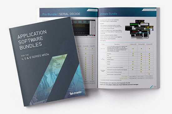
Application Software Bundles
Application Software Bundles combine multiple measurement and analysis options for much less than the cost of individual options. They can be a great value, especially if you have a diverse workload.
Find out more in Solution Bundles for 4, 5 and 6 Series MSOs
Individual software options are listed on the next page
Serial Bus Decoding, Compliance/Conformance Testing and Advanced Analysis
Listing of individual software options
| Options | 3 Series MDO | 4 Series B MSO | 5 Series B MSO | 6 Series B MSO | |
| Serial Decode Options | 1-Wire serial decoding and analysis | ⬤ | ⬤ | ⬤ | |
| 8b10b serial decoding and analysis | ⬤ | ⬤ | |||
| Aerospace serial trig. and analysis (MIL-STD-1553, ARINC429) |
⬤ | ⬤ | ⬤ | ⬤ | |
| Audio serial trig. and analysis (I2S, LJ, RJ, TDM) | ⬤ | ⬤ | ⬤ | ⬤ | |
| Automotive serial trig. and analysis (CAN, CAN FD, LIN, FlexRay) |
⬤ | ⬤ | ⬤ | ⬤ | |
| Automotive sensor serial triggering and analysis (SENT) | ⬤ | ⬤ | ⬤ | ||
| Computer serial triggering and analysis (RS-232/422/485/UART) |
⬤ | ⬤ | ⬤ | ⬤ | |
| CXPI serial decoding and analysis | ⬤ | ⬤ | ⬤ | ||
| Embedded serial triggering and analysis (I2C, SPI) | ⬤ | ⬤ | ⬤ | ⬤ | |
| EtherCAT serial decoding and analysis | ⬤ | ⬤ | ⬤ | ||
| Ethernet serial triggering and analysis (10BASE-T, 100BASE-TX) |
⬤ | ⬤ | ⬤ | ||
| eSPI serial decoding and analysis | ⬤ | ⬤ | ⬤ | ||
| eUSB2 serial decoding and analysis | ⬤ | ⬤ | ⬤ | ||
| I3C serial decoding and analysis | ⬤ | ⬤ | ⬤ | ||
| Manchester triggering and analysis | ⬤ | ⬤ | ⬤ | ||
| MDIO serial decoding and analysis | ⬤ | ⬤ | ⬤ | ||
| MIPI D-PHY (CSI/DSI) decoding and analysis | ⬤ | ⬤ | |||
| NFC (ISO/IEC 15693, 14443A, 14443B, and FeliCa) | ⬤ | ⬤ | ⬤ | ||
| NRZ serial decoding and analysis | ⬤ | ⬤ | ⬤ | ||
| Power management serial triggering and analysis (SPMI) | ⬤ | ⬤ | ⬤ | ||
| PSI5 serial decoding and analysis | ⬤ | ⬤ | ⬤ | ||
| SDLC serial decoding and analysis | ⬤ | ⬤ | ⬤ | ||
| SMBus serial decoding and analysis | ⬤ | ⬤ | ⬤ | ||
| SpaceWire serial decoding and analysis | ⬤ | ⬤ | ⬤ | ||
| SVID serial decoding and analysis | ⬤ | ⬤ | ⬤ | ||
| USB serial triggering and analysis (USB 2.0 LS, FS, HS) | ⬤ | ⬤ | ⬤ | ⬤ | |
| Compliance Options | Automotive Ethernet (10BASE-T1S) compliance solution | ⬤ | |||
| Automotive Ethernet (100BASE-T1, 1000BASE-T1, 10BASE-T1S) automated compliance test application |
⬤ | ⬤ | |||
| DDR3 and LPDDR3 automated compliance solution | ⬤ | ||||
| Ethernet (2.5G and 5G BASE-T) automated compliance solution | ⬤ | ||||
| Ethernet (10G BASE-T) automated compliance solution | ⬤ | ||||
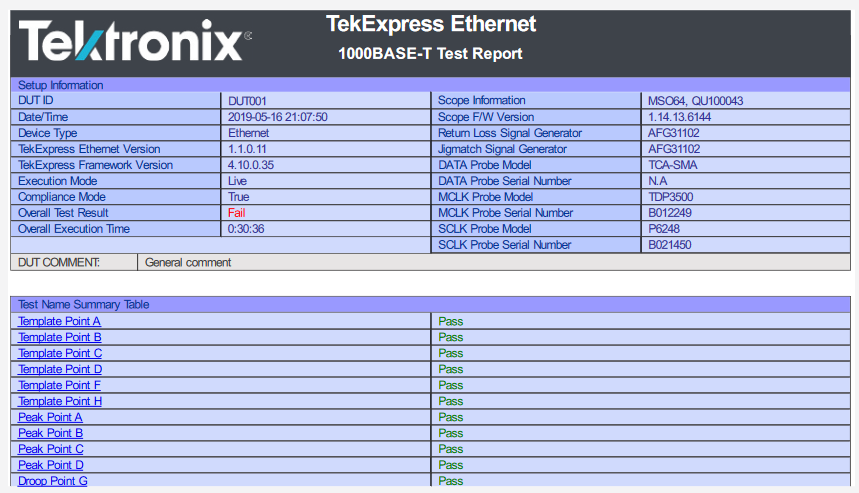
| Ethernet (1000BASE-T, 100BASE-T, 10BASE-T, 10Base-T1L) automated compliance solution | ⬤ | ⬤ | |||
| MIPI D-PHY 1.2 automated compliance solution | ⬤ | ||||
| MIPI C-PHY 2.0 automated compliance solution | ⬤ | ||||
| MIPI D-PHY 2.1 automated compliance solution | ⬤ | ||||
| Multi-Gigabit Automotive Ethernet (2.5G/5GBASE-T1) automated compliance solution | ⬤ | ||||
| USB2.0 automated compliance test solution | ⬤ | ⬤ | |||
| Analysis Options | 3-phase, inverter, motor, drive analysis | ⬤ | ⬤ | ||
| 3-phase power measurements and analysis | ⬤ | ||||
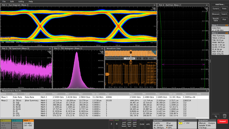
| Advanced jitter and eye analysis | ⬤ | ⬤ | |||
| Advanced power measurement and analysis | ⬤ | ⬤ | ⬤ | ||
| Basic power measurements and analysis | ⬤ | ⬤ | |||
| DDR3 and LPDDR3 analysis and debug | ⬤ | ||||
| DQ0 measurements for inverter motor drives | ⬤ | ⬤ | |||
| Enhanced security for instrument declassification | ⬤ | ⬤ | ⬤ | ⬤ | |
| Mechanical measurements for inverter motor drives | ⬤ | ⬤ | |||
| Removable SSD with Windows license | ⬤ | ⬤ | |||
| RF vs Time traces, triggers, spectrograms and IQ capture | ⬤ | ⬤ | ⬤ | ||
| User-defined filter creation tool | ⬤ | ⬤ | |||
| Vector signal analysis (SignalVu-PC) | ⬤ | ⬤ |
High Speed Digitizers
These low profile digitizers are essentially full-featured 5 and 6 Series oscilloscopes in a compact 2U "rack ready" form factor. They offer the same graphical user interface and performance but in a much smaller package.
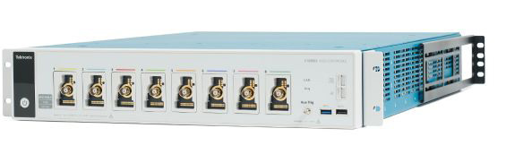
5 Series B MSO Low Profile
The 5 Series B MSO is available in a 2U low-profile form factor.Eight channels and 12-bit ADCs set a new standard when extreme channel density and measurement performance are required.
- 1 GHz bandwidth
- 6.25 GS/s sample rate
- 8 FlexChannel inputs
- Record length from 125 M to 500 M
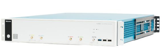
6 Series Low Profile Digitizer
The 6 Series Low Profile Digitizer sets a new standard for performance by not interleaving sample rate, bandwidth or record length. You get the fastest and most accurate performance from your digitizer – all in a 2U space.
- 1 GHz to 8 GHz bandwidth
- 25 GS/s sample rate
- 4 inputs
- Record length from 125 M to 1 G
Find more valuable resources at TEK.COM
Copyright © Tektronix. All rights reserved. Tektronix products are covered by U.S. and foreign patents, issued and pending. Information in this publication supersedes that in all previously published material. Specification and price change privileges reserved. TEKTRONIX and TEK are registered trademarks of Tektronix, Inc. All other trade names referenced are the service marks, trademarks or registered trademarks of their respective companies.
1/2024 48W-61573-5