Introduction
Many thermoelectric cooler (TEC) controllers use PI or PID (proportional, integral, derivative) loops for temperature control.While these loops can provide precise temperature control, they require proper values for each P, I, and D term. Many times, these terms are established through trial and error, which is time consuming, difficult, and may result in longer than necessary temperature settling times. In a production test environment, this difficulty is multiplied if several temperature setpoints or different devices must be evaluated on a routine basis.
What is Autotuning?
Autotuning provides an automated way to determine good values for each term in the Model 2510-AT TEC SourceMeter Instrument's temperature control loop for TEC devices. The autotune process is performed once for each desired system setpoint. The 2510-AT autotune algorithm applies a voltage step function across the TEC or Peltier device. Information from the temperature response of the system is extracted and applied to a modified version of the Ziegler-Nichols tuning technique, providing two sets of PID coefficients. One set is optimized for minimum temperature overshoot, while the other is optimized for minimum settling time. Either set may be chosen for use, depending on test requirements or device limitations. If desired, these numbers may also be used as starting points when finetuning the system response.
The Model 2510-AT's autotune algorithm assumes that the system response to a step function in the Peltier voltage is an exponential temperature rise of the form:
Tsystem = Tinitial for t < tLag
Tsystem = Tinitial + Tstep (1 - e-(t-tLag)/Tau) for t ≥ tLag
This is depicted graphically:
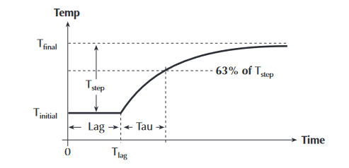
In this case, the temperature step is shown as being positive, but it could also be a negative step. The exponential response is typical for most TEC (Peltier) controlled laser diodes and fixtures. Temperature responses of a different mathematical model will cause the autotune function to fail (or give unpredictable results). Once the Lag and Tau times are extracted from the sampled data taken from the voltage step response, the tuning constants are calculated. See the section titled "Typical Sources of Error" for the limitations of the algorithm. See Chapter 4 in the Model 2510 User's Manual for a discussion of PID concepts.
Test Description
The system Tau is a measure of how quickly the system (2510 + TEC + fixture + device) can reach a given temperature. To permit the autotune algorithm to tune the widest possible range of devices, an initial value for the system Tau must be determined. The system Tau can range from three to 30 seconds for a laser diode module to more than 300 seconds for a larger fixture.
Laser Diode Modules
The autotune algorithm was designed to determine good PID coefficients for TEC-equipped Laser Diode Modules (LDMs) designed for communications. These LDMs typically have a short Tau, so autotuning takes from five to 15 minutes.
Test Fixtures
In addition to LDMs, the autotune algorithm has settings that permit tuning test fixtures, which have much longer system Tau values. When tuning test fixtures, the system Tau must be set to a range similar to the actual system Tau. If the actual system Tau is unknown, set the Tau to "medium" and if autotuning is not successful, use a long Tau setting and attempt autotune again.
Autotune Process
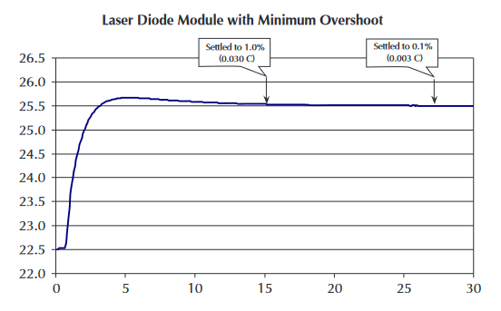
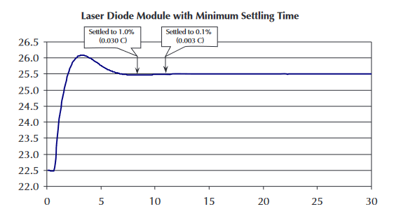
When completed, the autotune algorithm supplies two sets of PID values: minimum overshoot and minimum settling time. The minimum overshoot set protects the DUT from thermal damage, and is useful for temperature setpoints near the maximum specified temperature of the DUT (Figure 2). For setpoints that do not approach the maximum specified temperature, the minimum settling time PID set can be used to decrease the settling time (Figure 3). Figures 2 and 3 show an example of a laser diode module using a 3°C temperature step (from 22.5°C to 25.5°C).The settling time for the minimum overshoot response is about twice as long as the minimum settling time response.
The time required to complete an autotune procedure depends on the thermal characteristics of the DUT (TEC cooling/heating power, thermal mass), ambient temperature, and the temperature step start and stop settings. However, five minutes is a rough estimate for a typical laser diode module.
The start and stop temperature for the autotune temperature step must be supplied before invoking autotune. It is also necessary to set the protection limits for temperature (LOLIM and HILIM) as well as the maximum voltage and current that the TEC can accommodate. All six values must be entered before the autotune will be allowed to run. Note that the autotune process is for temperature-based control ONLY. The start temperature for the autotune procedure is simply the beginning temperature for the step. The stop temperature for autotune is the desired temperature setpoint or the desired operating temperature for the laser or fixture.
The 2510-AT displays five status messages during the autotune process:
Measuring System Temp - The 2510-AT applies 0V to the output and checks for a constant fixture+DUT temperature.The autotune algorithm assumes that when it is invoked, the system temperature has already stabilized to the zero voltage/non-excited steady state.
Applying Initial Step - During this step, a preliminary set of PID values is determined.
Seeking Prog Stop Temp - Proper voltage setting is determined for the stop temperature.
Seeking Prog Start Temp - Proper voltage setting is determined for the start temperature.
Applying Final Step - Autotune temperature step is applied, with the extracted results being applied to the Ziegler-Nichols algorithm, creating the two sets of PID coefficients.
The progress indicator, located in the lower right corner of the instrument display, shows whether or not the autotune process is active.
Test System Configuration
Connect the TEC portion of the Device Under Test (DUT) as shown in Figure 4. See the "Methods and Techniques" section for cabling resistance requirements.
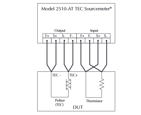
Note that the Model 2510 assumes that a positive current heats the DUT. Many laser diode TEC applications assume that a positive current cools the DUT; therefore, swap the + and – output lead connections for applications where a positive current cools the DUT (as shown in Figure 4). The swap has no negative effect on the 2510 or TEC performance.
The 4-wire mode is required for the output and is recommended for the input (temperature sensor) when using a thermistor or RTD for best accuracy. For the input connections, 2-wire mode (no sense connections) is used for solid-state sensors (e.g., AD590, LM335).
The autotune feature can only be activated remotely, via the GPIB or RS-232 ports, so a computer and the appropriate accessories (cable or GPIB card and cable) are required, as outlined in the section titled "Equipment List."
SCPI Programming
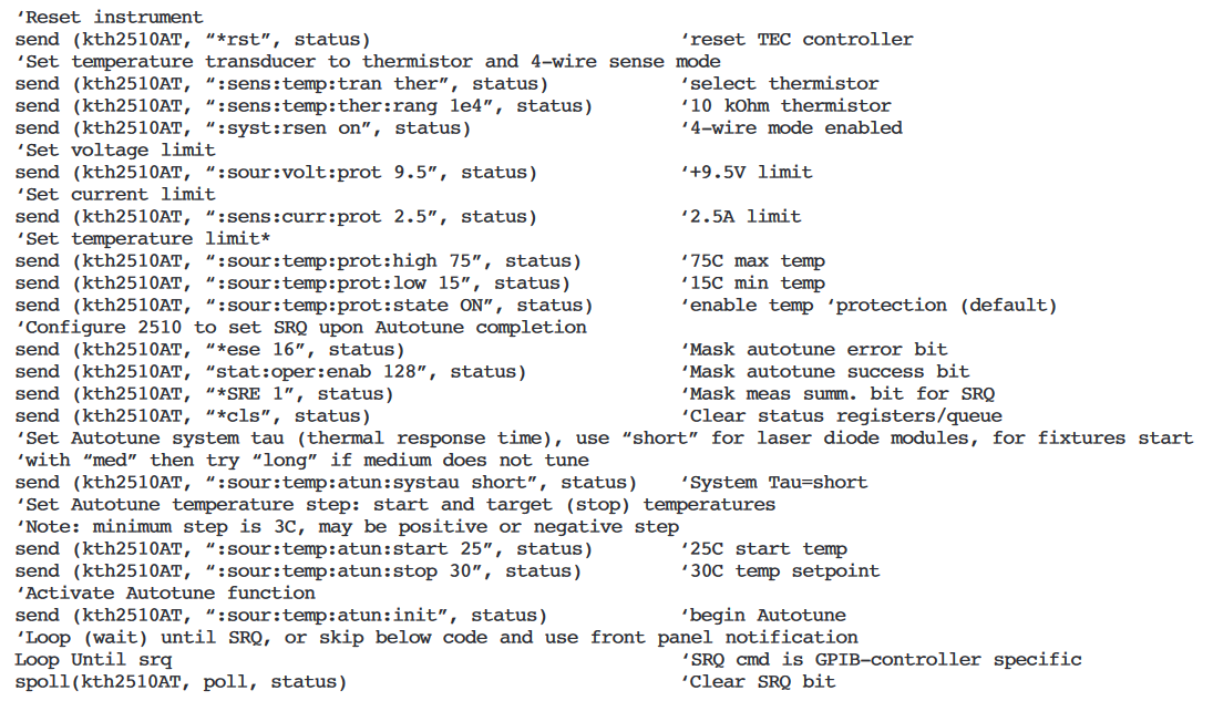
1. Set protection limits for the TEC (Peltier device), autotune parameters, and start autotune session:
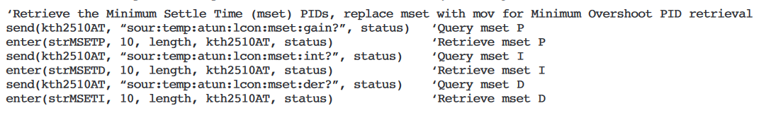
2. After the autotune process is complete, the status (complete or error) will be displayed briefly. See "Error Messages" for SCPI programming to retrieve the autotune status. After a successful autotune session, the two sets of PID values are available. To use the new PID set, see step 3. It is also possible to view the autotune PID sets by retrieving them from the instrument:
3. A successful autotune session results in two sets of PID values. To use a set of autotune PID values, transfer the desired set to the active PID set. Note that the autotune results are stored in volatile memory and are erased by an instrument reset or power cycle. See step 7 for a method to save the desired PID set.
3.1 Use minimum temperature settling time PID coefficients:

3.2 Or, use the minimum overshoot response:

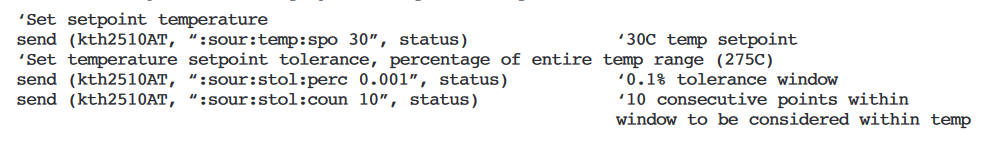
4. After choosing the PID values, program the setpoint and setpoint tolerance:
5. The Fahrenheit temperature scale may be used instead of Celsius (°C is the default):

6. Now, the Model 2510-AT is ready to control temperature. Initiate the control loop by pressing the ON/OFF key on the front panel or initiate it remotely by using this command:

7. If the PID coefficients provide acceptable performance, save the settings in the Model 2510-AT's non-volatile memory:

8. The Model 2510-AT can be configured to power-on with the saved configuration:

Methods and Techniques
Cabling
The maximum sense lead resistance is 1Ω for each sense lead. The maximum force lead resistance is 0.1Ω. Force cabling with resistance higher than this maximum value can cause instability in the PID loop or an apparently false voltage limit indication (Vlim). The warning appears to be false because the output voltage at the TEC will be less than Vlim, but adding the cable IR voltage drop means that Vlim is exceeded on the output force cable ends nearest to the Model 2510-AT.
TEC Characteristics
The gain of a Peltier varies with operating temperature and increases with increasing temperature. This variation can be as much as 7-to-1 over the Peltier's operational temperature range. This change in operational efficiency is largely due to the fact that the I2R heating generated by the normal operation of the Peltier Junction adds to the efficiency of the junction when pumping heat into the load, but subtracts from the efficiency of the junction when cooling the load. This change in Peltier gain will cause the overall system characteristics (and hence, the tuning constants that will control it) to change appreciably over the entire operating temperature range of the system. This is why it's important to tune the PID loop at the system's actual operating temperature. Ideally, if a setpoint changes by more than 10°C, a new set of tuning constants should be generated to control it. These new constants can be written into the registers of the Model 2510-AT "on the fly" via GPIB commands before issuing the new temperature setpoint.
Performing consecutive autotune procedures on a TEC will not provide identical PID coefficients. That's because the initial conditions for the TEC will not be identical from run to run. Each run in consecutive autotune procedures will have different initial temperatures for the DUT, TEC, and heat sink. These differences are sufficient to produce unique PID values.
Multiple Setpoints with One Set of PID Values
If a single set of PID values will be used for more than one temperature setpoint, use the higher temperature setpoint for the autotune stop temperature. Using the higher temperature setpoint will incorporate the higher inherent gain of the TEC, resulting in a lower P value. Using PID values determined at a lower temperature setpoint at a much higher temperature setpoint may result in oscillation or system instability, due to the higher gain of the TEC at higher temperatures. Averaging the constants from both extremes is not advisable because of poor performance at both operating points – more overshoot and ringing at high temperatures and a slower response at lower temperatures.
Large Temperature Steps
If a protection limit (current, voltage, or temperature) is exceeded during the autotune process (specifically in the initial or final step phases of the autotune algorithm), the process will fail, producing an error message indicating the fault. Given that the autotune algorithm uses an open loop temperature step, large temperature steps are more likely to cause a protection limit to be exceeded, usually a current or voltage limit. If a large temperature step is desired, use a smaller tuning step by making the start temperature closer to the stop temperature. For example, rather than a step of 25°C to 70°C, try a 65°C to 70°C step.
Managing Multiple Sets of PID Coefficients
A successful autotune session provides two sets of coefficients: one for minimum temperature overshoot, one for minimum temperature settling time. A working set of PID values is used for temperature control. For the Model 2510-AT to use the autotune results, one set of PID coefficients must be transferred to the working set. Step 3 in the "SCPI Programming" section shows how to transfer a chosen set of PIDs from the autotune session to the operational set. Note that all three sets of coefficients are stored in volatile memory, so these coefficients will be lost if there's a power cycle or instrument reset. Using the command in Step 7 will save the operational set to an instrument setup. To retain the two sets of PIDs from the autotune session, transfer them to the operational set, then save in an instrument setup as shown in Step 7. Take care to note the save setup number of each PID set. It is also possible to save them by recording the values after querying the instrument using the commands in Step 2.
PID Tweaking and PID Terms
The Ziegler-Nichols algorithm used by the autotune process provides good, but not perfect, PID values. If the autotune algorithm does not produce the desired response, use the numbers created by the autotune algorithm as a starting point and work from there to create the desired performance. The following is an intuitive explanation of what each term does:
Kp(Proportional gain constant)—This is the number that "pushes" the system to its final value. Lower numbers create a slower response; larger numbers help increase the response speed. Excessively large values can cause the system to oscillate and/or become unstable.
Ki(Integral gain constant)—This number is responsible for how fast the system settles to its final value, as well as the amount of overshoot in the response. Low numbers create a long settling tail with minimal overshoot; large numbers settle much more quickly but with greater overshoot. Excessively large values can cause to system to become unstable (and probably oscillate).
Kd(Derivative gain constant)—This number restricts rapid system temperature movements. Small values allow the system temperature to change essentially without restriction. Large values place greater restrictions on rapid temperature movements. Modify this number to control how the system responds to large temperature changes.
Typical Sources of Error/Limitations
Common Problems
A temperature overrange (ORR) may occur because the force output wiring is reversed. This may be easily observed from the Model 2510-AT's front panel. If the present temperature is moving farther away from the setpoint for several seconds before the ORR status indicator appears, the outputs F+ and F– probably need to be swapped. The Model 2510-AT assumes that a positive voltage/current heats the DUT (see Figure 4).
Note that the autotune PID coefficients, and protection limits are stored in volatile memory. To maintain the desired settings, save the instrument configuration. See Steps 7 and 8 in the section on SCPI programming for details.
Error Messages
If the autotune process fails, an error message will be displayed briefly. This error message can be retrieved from the system error queue with these commands:
This error message indicates the ambient temperature, measured throughput of the autotuning process, was too unstable (rough temp variability?). This error may be eliminated by blocking any air currents from the area around the fixture and insulating the DUT/TEC fixture even more than it is already
Error +816 Insufficient Temperature Step
This error message typically indicates the system Tau is longer than specified, resulting in a temperature that did not reach the target (i.e., final) temperature. If tuning a fixture, start with Tau = med. Potential causes are that the TEC connection has an open circuit or that the Peltier gain (Volts/°C) is too low, or the thermal mass of the fixture is too large.
Error –230 Data Corrupt or Stale
If received while attempting to transfer autotune PID coefficients, this error indicates that the autotune session was not successful.
Autotuning Fixtures (Long Tau) Problems
The initial portion of the autotune algorithm determines when the system temperature is stable. The longer Tau systems require a longer sampling time to determine when the system temperature is stable. This long measurement time means that ambient temperature fluctuations can have a negative effect on temperature measurement. If the temperature is changing or drifting,
error "831 Autotune—Ambient Unstable" may occur. Eliminating temperature fluctuations will help eliminate this error condition. If the fluctuations in the ambient environment cannot be reduced, the thermal insulation of the DUT and fixture will minimize these effects. The autotune function can accommodate Tau values between one and 450 seconds.
Algorithm Limitations
Several limitations inherent to the Model 2510-AT's autotune function can cause it to fail:
1. A temperature step less than at least 3°C.
2. A system Tau time of less than one second or greater than 450 seconds.
3. A system Lag time greater than 0.6 · Tau.
4. Ambient temperature outside the range of the HILIM and LOLIM values.
5. Ambient temperature movements of greater than ± 0.010ºC during the autotune sequence.
6. Noisy temperature measurements. Air currents around the DUT or temperature sensor may cause the system temperature to wander (i.e., not settle out to a final value). Also, poor thermal contact between the temperature transducer and the DUT can cause oscillation or other system-related problems.
7. Reaching any temperature, current, or voltage protection limit during the initial or final autotune voltage step test.
8. A TEC (Peltier element) resistance that's greater than 80Ω. Use the AC Ohms feature of the Model 2510-AT to determine the TEC resistance.
9. Testing devices with resistive heaters. The autotune algorithm was not designed to accommodate resistive heaters.
Equipment List
• Model 2510-AT Autotuning TEC SourceMeter® instrument
• KPCI-488 IEEE-488.2 Interface for PCI Bus (or other GPIB/IEEE-488 interface card)
• 7008-3 IEEE-488 (GPIB) Cable 3 ft (0.9 m)
• 7009-5 RS-232 Cable (for applications not requiring GPIB speed or expansion capabilities)
• Extra Connector CS-846 (optional, one CS-846 included with 2510/2510-AT)
• 2510-CAB (optional, depending on test cabling requirements)
Related Documentation
For Model 2510-AT applications in L-I-V testing, refer to "High Throughput DC Production Testing of Telecommunications Laser Diode Modules" (Number 2214)
Example Program
Keithley has developed an example Visual Basic program to configure and launch an autotune session with the Model 2510-AT. This free program can be downloaded from the Keithley website: http://www.keithley.com
Find more valuable resources at TEK.COM
Copyright © Tektronix. All rights reserved. Tektronix products are covered by U.S. and foreign patents, issued and pending. Information in this publication supersedes that in all previously published material. Specification and price change privileges reserved. TEKTRONIX and TEK are registered trademarks of Tektronix, Inc. All other trade names referenced are the service marks, trademarks or registered trademarks of their respective companies.
No.2364 2022KGW