Introduction
Increasingly, mobile devices and other portable designs are adopting System Power Management Interface (SPMI) protocol for multimaster, multi-slave systems to monitor and dynamically control supply voltages based on real-time system demands. This enables designers to achieve lower power usage at the system level.
SPMI is an industry standard for communicating DC power rail commands to power management ICs (PMICs) in a variety of embedded systems. Though the SPMI buses are well-defined and are designed to be robust and easy to integrate, serial communications can be affected by noise, board layout, reset issues, and subtle differences in implementations. These can sometimes result in bus errors and system malfunctions.
Unlike basic protocol analyzers, oscilloscopes equipped with protocol decoding, can be used to see both the decoded bus traffic, as well as signal quality. This ability to see bus signals and decoded traffic makes oscilloscopes the best choice for visualizing overall system operation. Perhaps more importantly, oscilloscopes can be used to troubleshoot problems at the system level. Oscilloscopes are well-suited for looking at power supply signals and bus transactions at the same instant. Because of this capability, they are the instrument of choice for system-level debugging.
THIS APPLICATION NOTE
- Gives a brief orientation on the physical layer and packet structures of SPMI, with a goal of providing just enough detail to help with troubleshooting
- Explains how to set up decoding on an oscilloscope equipped with SPMI decoding
- Explains how to interpret SPMI packet data
- Explains what triggering and searching options are available on an oscilloscope equipped with SPMI serial triggering and analysis
Detailed specifications of the SPMI protocol are available from the MIPI Alliance at mipi.org.
With the optional serial triggering and analysis capability, Tektronix oscilloscopes become powerful tools for embedded system designers working with SPMI buses. In this application note, the 5 Series MSO is used to demonstrate SPMI serial bus decoding and triggering. Other Tektronix oscilloscopes also support SPMI triggering and analysis. See "Serial Support Using Oscilloscopes and Optional Software" for a complete listing.
SPMI
The MIPI (Mobile Industry Processor Interface) System Power Management Interface (SPMI) is a serial bus interface between processors and peripheral components for advanced power management. This interface was developed by the System Power Management Working Group of the MIPI Alliance. The MIPI Alliance is a global organization that develops interface specifications for the mobile ecosystem including mobile-influenced industries such as PCs, tablets, cameras, and IoT devices.
SPMI is used primarily for system power management and may also have applicability as a general-purpose bus. SPMI is chiefly used for communication between power controllers and devices in a system to manage the overall power usage based on performance requirements.
HOW IT WORKS
The SPMI interface is a high-speed, bidirectional, low-latency, serial bus. It uses a CMOS physical layer to implement a two-wire serial interface:
- SDATA: a bidirectional serial data signal
- SCLK: a uni-directional clock signal
SPMI provides two device speed classes:
- High Speed (HS): 32 kHz to 26 MHz
- Low Speed (LS): 32 kHz to 15 MHz
The interface supports dedicated power management commands for Reset,Sleep, Shutdown, Wakeup, and Authenticate. It also supports generalpurpose Master-to-Slave, Slave-to-Master, Master-to-Master, and Slave-toSlave read/write commands.
Because SPMI is an industry standard and features low pin and low gate count, it can replace several custom legacy point-to-point interfaces. Each bus can support up to 4 masters and 16 slave devices. The standard defines both +1.2 V and +1.8 V CMOS signaling levels, and allows up to 50 pF loading on the signals. High-resistance pull-downs are used at or near the slave devices.
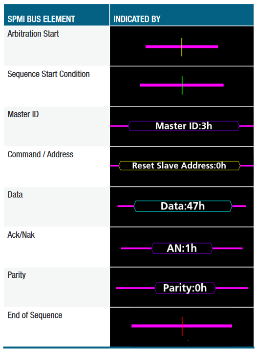
Bus transactions are referred to as sequences. The bus is only active during a sequence. Between sequences, the bus is idle (where both SDATA and SCLK signals are at logic low levels). A command sequence is composed of the following components:

- Sequence Start Condition (SSC): a positive pulse on SDATA while SCLK is low.
- Frame Transmission: a command frame and possibly one or more address/data frames.
- ACK/NACK: only used with some types of command frames.
- Bus Park Cycle: the master releases the bus and the bus either enters an idle state or another master takes control of the bus.
The types of frames that can be communicated in the Frame Transmission portion of a sequence include:
- Command Frame: four address bits followed by eight command bits and an odd parity bit.
- Data/Address Frames: eight data/address bits followed by an odd parity bit. The only distinction between the two types is what type of data is being communicated (address or data).
- No Response Frames: There are two types – No Response Command Frames and No Response Data/Address Frames. They are exactly like the frames described above but the content of all bits (including parity bits) are 0s.
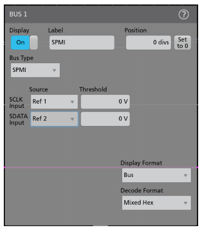
SETTING UP SPMI BUS DECODING
On Tektronix oscilloscopes equipped with SPMI decoding and triggering, pressing the front panel Bus button enables you to define inputs to the scope as a bus. Analog or digital channels may be defined as an SPMI bus. To enable the oscilloscope to decode the packet data. You enter some basic parameters, including:
- Input channels for clock and data signals
- Voltage threshold levels
The SPMI bus uses single-ended, ground-reference signals. Although the oscilloscope can acquire these signals and decode the bus using standard single-ended probing, the signal fidelity and noise immunity may be improved by using differential probing.
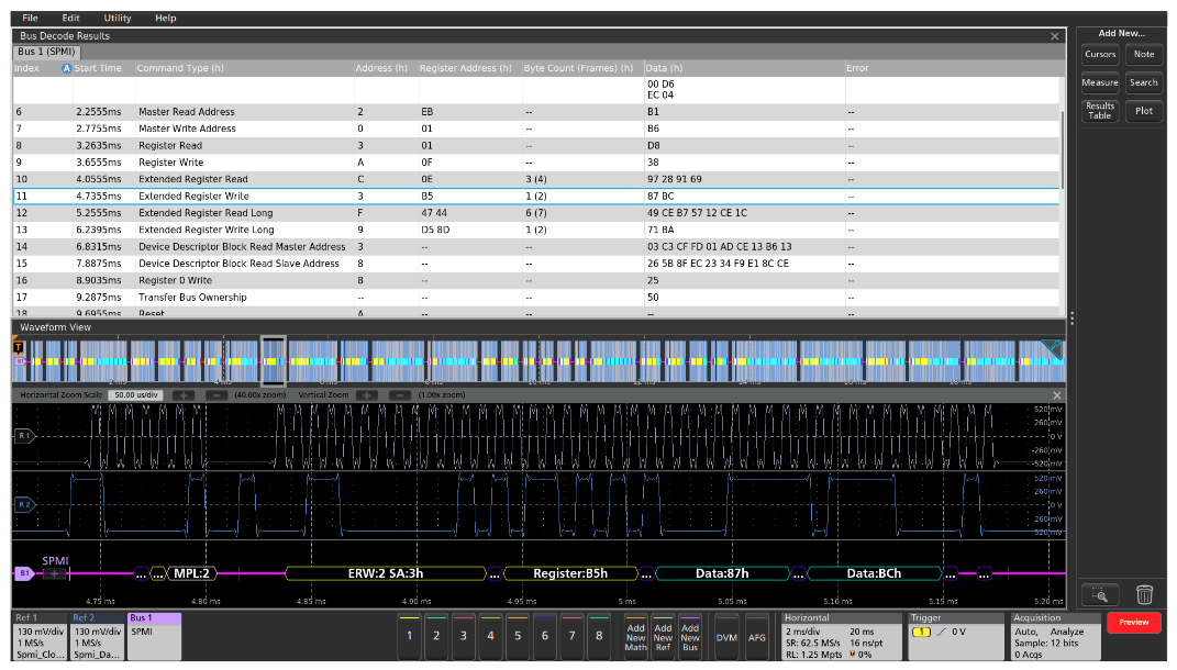
INTERPRETING THE SPMI BUS
The time-correlated waveform and bus decode display is a familiar and useful format for many hardware engineers. The decoded bus waveform indicates the elements of an SPMI sequence.
For firmware engineers, the Results Table format may be more useful. This time-stamped display of bus activity can be easily compared to software listings, and allows easy calculation of the execution speed.
The Results Table also provides linkage back to the waveform displays. You can tap a line in the tabular display and the oscilloscope automatically zooms in on the corresponding bus signals and resulting decoded bus waveform, shown in the lower section of the screen.
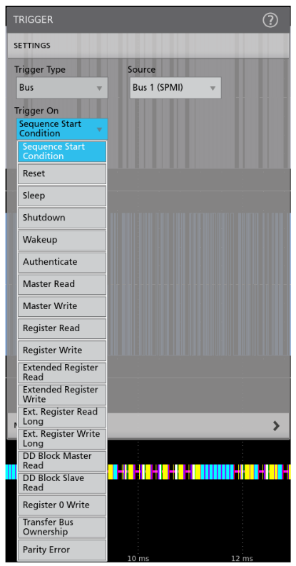
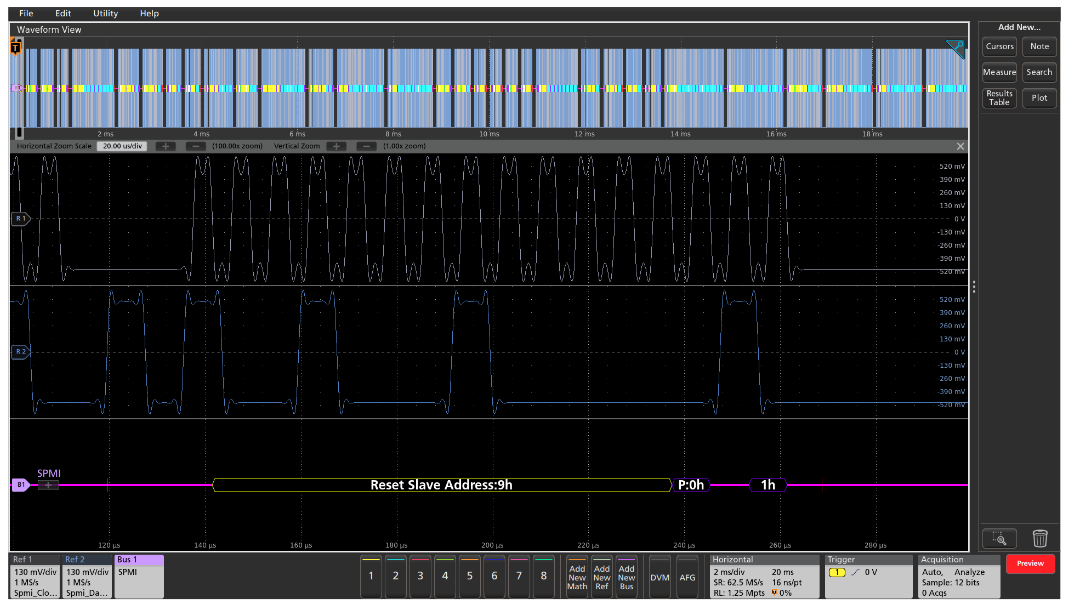
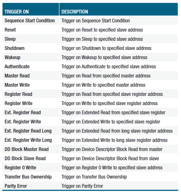
TRIGGERING ON THE SPMI BUS
When debugging a system based on one or more serial buses, one of the key capabilities of the oscilloscope is isolating and capturing specific events with a bus trigger. When the bus trigger is correctly set up, the oscilloscope will capture all the input signals and one specified bus event will be positioned at the trigger point.
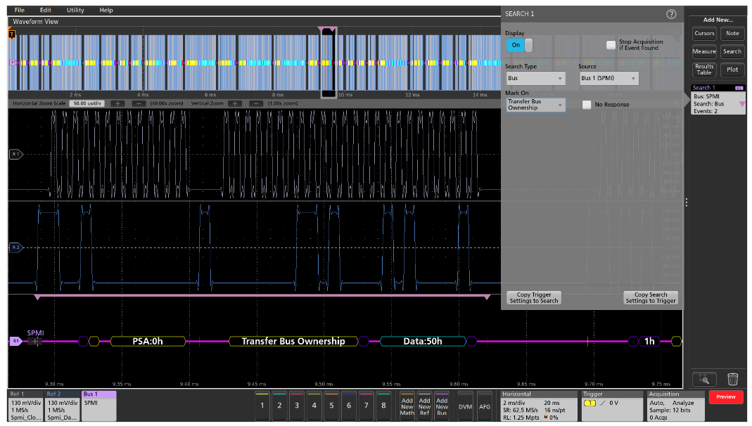
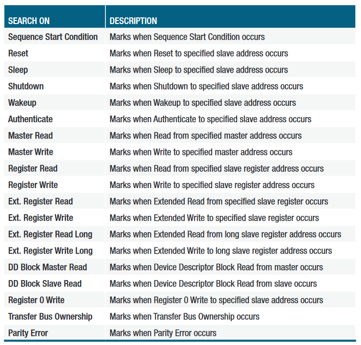
SEARCHING THE SPMI BUS
On a Tektronix oscilloscope, you can use the automated Wave Inspector search to find all the bus events that meet search criteria and determine how many of them occurred. The setup is similar to the bus trigger setup, and allows the oscilloscope to find and mark all of the same specified bus events. In this example, the automatic search is looking for the Transfer Bus Ownership command. This command occurs 2 times in the acquired waveforms and the positions of the specified serial data packets are shown with the pink bracket icons.