Introduction
As the move toward Automotive Ethernet technology in vehicles accelerates, comprehensive design validation is vital to ensure interoperability and reliable operation across multiple ECUs. In this application note, we will provide information on Automotive Ethernet, full-duplex communication, the need to separate master and slave signals, signal separation testing methodologies, and a comparison of the current directional coupler insertion method and the Tektronix new signal separation method.
Automotive Ethernet
Defined by the OPEN Alliance SIG, Automotive Ethernet, or IEEE 802.3bw (formerly BroadR-Reach), is an Ethernet physical layer standard designed for automotive connectivity applications, such as advanced safety features, comfort and infotainment features. Automotive Ethernet enables multiple in-vehicle systems to simultaneously access information over an unshielded single twisted pair cable. The benefits for automotive manufacturers include reduced connectivity costs and cabling weight, with greater signal bandwidth.
To achieve greater signal bandwidth, Automotive Ethernet utilizes a full-duplex communication link over a twisted pair cable with simultaneous transmit and receive capabilities with PAM3 signaling. Full-duplex communication with PAM3 signaling can make visualization of Automotive Ethernet traffic and signal integrity testing very complex.
Test specifications for Automotive Ethernet have been defined by the OPEN Alliance for component, channel and interoperability. The test system consists of integration of the Electronic Control Unit (ECU), connectors and untwisted cables. Testing requires the systems work under demanding environmental and noise conditions within the vehicle. For this reason, users need the ability to characterize and visualize signal integrity and traffic at the system level to perform reliability testing.
Examples of use case where customers need to conduct signal integrity testing at system level are:
- TC8 Signal Quality testing
- ECU component characterization and testing
- Automotive Ethernet cable, connector, cable length and routing characterization and testing
- Electromagnetic noise or Gaussian noise testing
- Bulk Current Injection testing
- Production unit testing
- Automotive system impact on Automotive Ethernet performance
– DC motor on/off
- Engine on/off - Automotive Ethernet system debug
Performing signal integrity testing at the design stage is recommended to identify potential issues prior to system integration.
Full Duplex Communication and the Testing Challenge
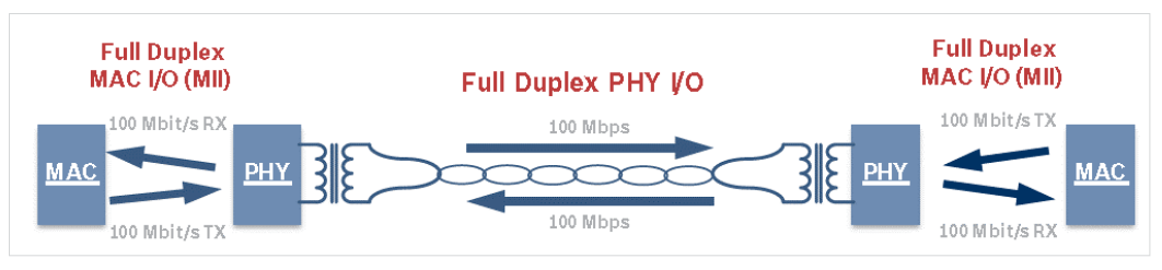
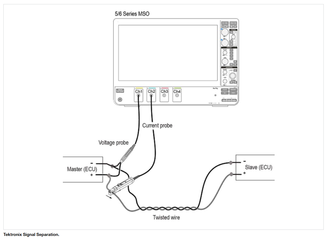
As mentioned above, full-duplex communication along with PAM3 signaling adds complexity in validating the ECUs in real world conditions. Where most serial standards operate in a simplex mode with only one device communicating at a time and some communication standards have a separate link for the transmit and receiver, with Automotive Ethernet, the Master and Slave device can communicate simultaneously over the same link. (See Figure 1.)
As a result, the signals from the master and slave are overlaid on each other. As the master knows what data it has sent, it can determine the slave’s signal from the overlaid signal and vice versa. While the transceiver is designed to handle this situation, it is virtually impossible on an oscilloscope to isolate the signal for signal integrity testing or protocol decode.
To perform signal integrity analysis over the link, and protocol decode in a real system environment on an oscilloscope, automobile designers need to look at each link separately, which requires the user to separate the signals before performing analysis.
It should be noted, it is very important to perform signal integrity testing at the vehicle integration phase to select the cable, check the ECU performance under the electromagnetic noise condition, determine optimal cable lengths and routing, etc. For this type of analysis, utilizing Eye Diagram testing can be a very valuable tool to visualize the health of the system and will be discussed below.
Separating Automotive Ethernet PAM3 Signals
Currently, there are two methods for separating master and slave signals. The first is the legacy method, requiring users to breaking, or cut, the Automotive Ethernet cable and insert a directional coupler to separate and test the signals. This method has inherent shortcomings for accurate testing with minimal disruptions. The second, Tektronix Signal Separation, is a new methodology that utilizes advanced software and probes to non-intrusively separate, allowing users to visualize the true signals with greater clarity. This method overcomes the drawbacks of the legacy directional coupler method. In this next section, we will discuss and compare the two methodologies.
The Directional Coupler Method
As mentioned, the directional coupler approach requires breaking the Automotive Ethernet cable and inserting a directional coupler to separate the traffic. It is not easy to cut the cable at system level, which makes this method not viable to use for system level testing.
While this lets users see the master and slave signals, it introduces Insertion and Return loss, which can make it difficult to determine if an error is a result of the system or the additional hardware. And, while it is possible to remove the effects of the directional coupler, de-embedding can amplify the noise in the systems and impact measurement and characterization accuracy
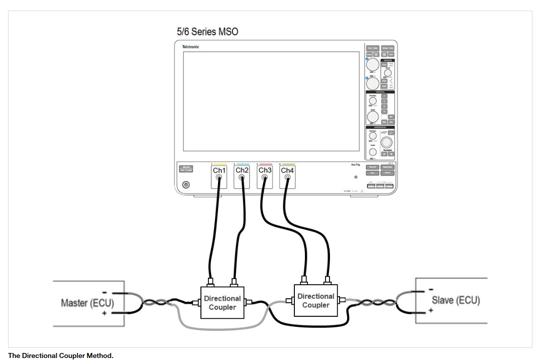
The setup we used includes Fixture to convert Automotive Ethernet to SMA connector, Directional Coupler and Fixture to convert SMA to Automotive Ethernet cable.
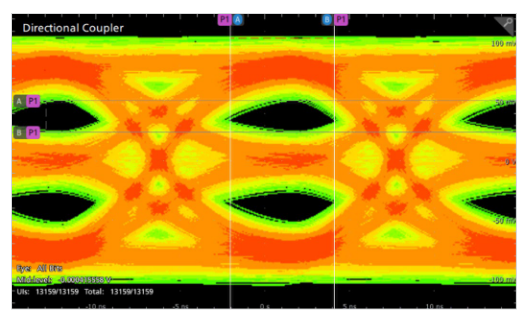
The eye diagram illustrates the impact of Insertion and Return Loss on Automotive Ethernet signals with a directional coupler installed. The max amplitude is 100 mVpp as the directional coupler works on a directivity principle. The insertion and return loss results close the eye diagram.
Until recently, the directional coupler approach was the default Automotive Ethernet testing methodology, as Tektronix software-based Signal Separation testing did not exist.
Tektronix Signal Separation
Tektronix Signal Separation, introduced in July 2019, separates the full-duplex signal by looking at voltage and current waveforms from both the master and slave test points and provides separated signals using a proprietary software algorithm. Tektronix Signal Separation is a software-based solution that does not require cutting the Automotive Ethernet cable, enabling users to see the true signal. One of the advantages of this method is it displays Master and Slave signals without adding insertion and return loss and the deembedding impact of the directional coupler method.
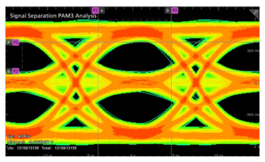
The eye diagram below utilizes Tektronix Signal Separation software. In comparison to the directional coupler eye diagram, the signal quality is higher with “cleaner” eyes. This provides users with an accurate representation of Automotive Ethernet signals for signal quality measurements and the ability identify potential performance issues faster
Comparing Signal Separation and the Directional Coupler Methods
Using the test methods described above, we ran measurement tests to compare the two.
For the test, we first set up and ran tests using Tektronix Signal Separation, a current and voltage probe. For the directional coupler method, the Automotive Ethernet cable was cut, and directional couplers with SMA connectors were inserted. We then ran the tests, using the same test conditions with the directional coupler method, recalled the Signal Separation waveforms and compared the test methods.
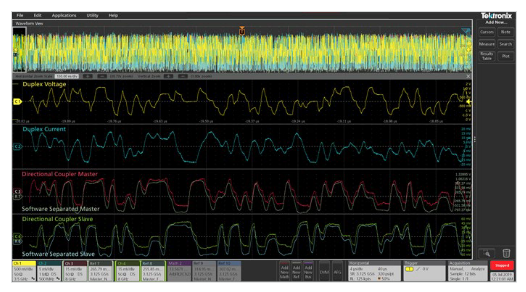
The comparison showed a significant amplitude difference between the two methods demonstrating the impact of the directional coupler. In the case of the directional coupler method, the amplitude was approximately 90 mVpp (Peakto-Peak Voltage) for the master and 85 mVpp for the slave. In comparison, the Signal Separation method had an amplitude of approximately 1.5 Vpp for the master and 1.45 Vpp for the slave. In this case, the directional coupler adds a 20 dB loss.
To offset the discontinuities introduced by the directional coupler, de-embedding becomes necessary to compensate for the insertion and return loss. As discussed above, while it is possible to remove the effects of the directional coupler, de-embedding can amplify the noise in the systems and impact measurement and characterization accuracy. It should also be noted that de-embedding can be time consuming and challenging. In addition, for system level testing and maintenance servicing of an automobile, it can be challenging to cut the cable and install directional couplers.
In comparison, the Signal Separation method shows the true signal without disrupting the system. This new Automotive Ethernet test methodology allows users to characterize signals with greater accuracy and in less time without the additional expense and measurement challenges. This method allows users to perform Signal Integrity tests at the system level and perform all tests mentioned in use cases.
Summary
In this paper, we have provided information on Automotive Ethernet, full-duplex communication and the need to separate master and slave signals, signal separation testing methodologies, and a comparison of the current directional coupler insertion method and new Tektronix Signal Separation method.
In comparing the two Automotive Ethernet test methodologies, we have shown the advantages of the Tektronix Signal Separation solution. These advantages include accurate visibility of the true signal versus the directional coupler signal, simplified test set-up at the component and system level, and reduced test time supporting full life-cycle automotive testing needs.
For more information on Signal Separation, Automotive Ethernet Signal Integrity Analysis using PAM3 Analysis tools and Tektronix test solutions, please visit www.tek.com/automotive/automotive-ethernet or contact your Tektronix representative.


