

Contact us
Call
Call us at
Available 6:00 AM – 5:00 PM (PST) Business Days
Download
Download Manuals, Datasheets, Software and more:
Feedback
D-PHY Transmitter Test, Receiver, and Protocol Solutions
D-PHYTX, D-PHYXpress, SR-DPHY, and Moving Pixel Datasheet
More Information
- DPO7000
- DPO70000SX ATI Performance Oscilloscope
- Explore more Software models
Read Online:
D-PHYTX, D-PHYXpress, SR-DPHY, and Moving Pixel Datasheet
Tektronix D-PHYTX, D-PHYXpress, SR-DPHY, and Moving Pixel D-PHY Protocol solution provides one stop comprehensive solution for conformance and characterization of Transmitter, Receiver, and Protocol test requirement as per MIPI standards. Tektronix D-PHYTX automated solution provides easy way to debug and characterize D-PHY data links. D-PHYTX allows you to select all the electrical and timing measurements defined in MIPI D-PHY, up to v1.2 specification. The D-PHYXpress software enables flexible and intuitive receiver testing of D-PHY v1.2 specification designs with AWG70000 Series Arbitrary Waveform Generator.1
1See the host system requirements in the Ordering Information section.
Key features
Transmitter testing:
- Test time
- Fully automated solution: Performs D-PHY transmitter test with single-button click, seamlessly across High Speed (HS), Low Power (LP), Low Power-High Speed (LP-HS) and Ultra-Low Power State (ULPS) sequences in the D-PHY signal.
- Allows to select individual test or group-wise tests through the tree structure.
- RF Switch support to handle multi-lane test with zero manual intervention.
- 100% test coverage as per D-PHY v1.2, CTS v1.2
- Performs all fully-automated tests, including Bus Turn Around (BTA) and Ultra-Low Power State (ULPS) measurements, as per D-PHY specifications up to v1.2.
- Debug features
- Modify limits of test parameters in TekExpress for debug and characterization.
- Provides DPOJET based setup files to debug the root cause analysis of failures.
- Measurement accuracy
- D-PHYTX application handles multitude scenarios like Continuous or Burst mode, Termination variations, and varying idle time.
- Transmitter conformance test and beyond
- Custom limits to perform margin testing
- Performs characterization by running TekExpress application in continuous mode and collect the data.
- Signal access
- P7700 Series High Impedance TriMode probe (D-PHY Essentials only) designed especially for MIPI application, that requires low loading, single-ended/differential measurements.
- Provides TekFlex™ accessories for flexible probing
- Offline/Remote analysis
- Analyze live or pre-acquired waveforms
- Allows remote execution of tests
Receiver testing:
Simplified Receiver test setup
- Single setup to generate signal for D-PHY and C-PHY
- Easy to calibrate and provide repeatable result
- Direct synthesis method helps to create all types of stress with single box.
Test Coverage
100% Test coverage: D-PHYXpress application allows you to create D-PHY standard conformant test signals as per MIPI D-PHY v1.2 and v2.0 specifications.
Signal Fidelity
Best in class AWG70000 Series with sampling rate of 50 GS/s with 10 bit vertical resolution, to provide best signal fidelity for D-PHY signal generation.
Ease of Use
D-PHYXpress provides batch processing to create multiple test scenarios for rigorous test requirements.
Receiver conformance test and beyond
- D-PHYXpress application provides a platform for you to create wide range of stimuli to test the device beyond specification.
- You can program Data to Clock timing, Rise time and Fall time of Data/Clock, Program ESC, LP Command along with Programmable Stress as mentioned below:
HS mode stressors
Random Jitter and Deterministic Jitter
Embed Insertion Loss and De-emphasis
Spread Spectrum Clocking
Dynamic Skew (D-PHY)
LP mode stressors
eSpikeand Minimum Pulse TMIN-RX
Set up/hold time tolerance
Real-time skew control
- Offline signal generation
D-PHYXpress application can work in offline mode or from PC to control AWG remotely and generate D-PHY signals.
Scope based DSI-1 and CSI-2 Protocol Decode:
- Decodes DSI and CSI-2 buses in Low Power and High Speed states.
- Decodes both short packets, long packets and communications types such as Bus Turn Around (BTA), Escape Mode Commands, and Low Power data.
- Decodes the DCS command, ECC, checksum, data type, packet data, and others.
- Displays event table, search, and error indicators.
- Indicates missing sync, ECC, and checksum errors.
Moving Pixel D-PHY Protocol Generator and Decoder:
- D-PHY Protocol Generator
- Supports up to D-PHY v1.2, CSI v1.2, and DSI v1.2 protocols.
- Standalone instrument with simplified setup and operation.
- Supports MIPI D-PHY signaling up to 2.5 Gbps-per-lane, for 1-4 lanes.
- Provides automated video sequence construction according to the user-defined frame timing.
- Supports command insertion during looping video upon user command.
- Provides extensive scripting and macro-capability (macros can now contain video mode frames).
- D-PHY Protocol Decoder
- Monitors MIPI D-PHY traffic up to 2.5 Gbps-per-lane, for 1-4 lanes.
- Standalone instrument with simple setup and operation
- Provides Sniff Mode (high-Z) and Receive Mode (SMA, terminated) interfaces.
- Supports acquisition of contiguous D-PHY traffic using 1 GB capture memory.
- Provides Protocol Packet triggering, LP sequencing and State triggering, and ECC/CRC/Burst Error triggering.
- Provides real-time statistics: Bus activity, measured bit-rate, packet counts, and ECC/CRC error counts, etc.
- Acquires, decodes, and displays CSI2 v1.2, DSI v1.2 protocol packets and D-PHY 1.2 signaling states (earlier standards are also supported).
- Provides extensive search and display filtering capabilities.
- Provides extensive RPC remote-control capability.
Applications
D-PHY testing for:
- Automotive camera and display
- Mobile camera and display
- D-PHY interface design
- DSI-1 or CSI-2 verification
- System validation and integration
- Manufacturing test
Transmitter testing
D-PHYTX application
Single-button fully automated D-PHY testing
The Tektronix TekExpress® (TEKEXP) Automated Test software runs on Windows 7 operating system.
TekExpress software ordered with Option D-PHYTX provides an automated, simple, and efficient way to test D-PHY Transmitter interfaces and devices consistent to the requirements of the D-PHY Conformance Test Specification revision up to v1.2.
Automated testing – save time and resources
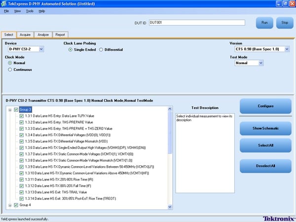
D-PHYTX allows you to select the desired tests to run and test the multiple lanes that to be tested. The automated solution, allows you to focus on design and debug of the measurements.
Setup test execution and reporting of measurements
Setup and test execution is simple with the TekExpress D-PHYTX software. The oscilloscope is controlled through the TekExpress automation framework. The TekExpress software provides a Graphical User Interface (GUI) and provides an intuitive workflow through setup and testing. D-PHYTX application provides GUI to select Test specification, Tree structure of HS, LP, HS-LP tests as per specifications, and Configuration for test condition.
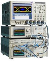
Setting up the bench
You can view the schematic of the selected test with a push of a button. It also displays graphical representation of the test connection to avoid human errors.
Pass/fail report
The report tab provides a view of test results along with pass or fail status, test margin, and images supporting the test results for each lane of the DUT.
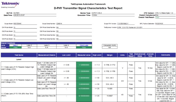
Pass/fail report
Beyond conformance - D-PHY Transmitter testing with D-PHY Essentials
DPOJET software with Option D-PHY provides the essential set of D-PHY Transmitter measurements with greater flexibility in the test setup. This option allows engineers to test device beyond conformance.
The following table outlines the key benefits from the DPOJET Option D-PHY and the TekExpress Option D-PHYTX software solution.
| Feature | Option D-PHY (D-PHY Essentials) | Option D-PHYTX (D-PHYTX Automated Solution) |
|---|---|---|
| Prerequisite tools | DPOJET Timing and Analysis | TEKEXP Automation |
| Automatic measurement selections based on device ID, test group, and selected probes | ✓ | |
| Single-button execution for all measurements | ✓ | |
| Configurable setup and editing of test limits | ✓ | ✓ |
| Detailed or summary reports | Detailed only | Detailed and Summary |
| Automatically save test reports and waveforms | ✓ | |
| Re-analyze prerecorded waveforms | ✓ | ✓ |
| D-PHY specific user interface | ✓ | |
| Conformance test specification revision | up to v1.2 | up to v1.2 |
P7700 probe (D-PHY Essentials only) for MIPI D-PHY
MIPI D-PHY application needs special type of probing as it operates in different impedance mode in High Speed and Low Power mode. In High Speed mode, D-PHY signals operate in terminated mode with differential signaling. In Low Power mode, D-PHY signal is operated in unterminated mode with single-ended signals. MIPI D-PHY has two main requirements for probing:
- Provide high impedance
- Differential and single-ended mode
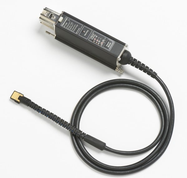
P7700 Series probe (D-PHY Essentials only) provides active buffer tip designed for Low Probe loading few millimeters from end of tip to provide best signal fidelity for MIPI D-PHY application along with flexible connectivity options.
With TriMode probing, probe setup makes differential, single-ended, and common mode measurements accurately. This unique capability allows you to work more effectively and efficiently, switching between differential, single-ended and common mode measurements without moving the probe's connection points.
You can be confident in the signal fidelity of your measurements. The innovative new probe design uses SiGe Technology to provide the bandwidth and fidelity needed today and in the future.
The P7700 Series probe (D-PHY Essentials only) architecture provides:
An active buffer amplifier on the tips with the probe input only 3.2 mm from the input
Excellent step response and low insertion loss up to 20 GHz
Low-DUT loading with 100 kΩ (DC) and 0.4 pF (AC) performance
High CMRR
Low noise
Switch Matrix support
The D-PHY application supports Switch Matrix option which enables fully automated testing for multi-lane D-PHY Transmitter test.
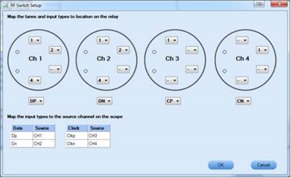
DPHY TEKXpress - Switch configurator
Advantages of Switch Matrix for D-PHY application:
- Multilane Testing: Switch Matrix eliminates reconnection and reduces errors through automating test setup for each lane of a multilane D-PHY bus.
- De-embed loss of Switch using S-Parameters to perform accurate measurements.
Test coverage
D-PHYTX application provides 100% test coverage as per D-PHY v1.2. For more details, refer to theTransmitter test specificationtable.
Receiver testing
The D-PHYXpress plugin creates D-PHY signals for High Speed, High Speed Burst, and Low Power content with worst-case impaired input signals.
Receiver test solution follows the below steps:
Generate test signal to emulate the transmitter including channel and noise impairments.
- Calibrate the signal as per the CTS requirement.
- Setup the Device for the receiver test.
- Determine the Bit Error Rate in the given test condition.
The D-PHYXpress application addresses the capabilities in the following step 1 and step 2:
Step 1: Generate test signal to emulate the transmitter including channel and noise impairments
The D-PHYXpress supports waveform generation for High Speed, Low Power, and Low Power-High Speed (LP-HS) mode as per D-PHY specification up to v2.0.
High Speed mode: The D-PHY v2.0 specification data rate is up to 4.5 Gbps in High Speed mode. As per CTS, you need to emulate the channel effect in High Speed mode. D-PHYXpress application allows you to edit the data rate, rise time, pattern type, voltage level, and impairments to emulate the channel effect.
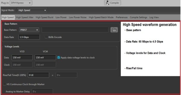
High Speed
In High Speed mode, you can add various channel effect such as: Periodic Jitter (Pj), Random Jitter (Rj), Dynamic Skew, Sine Noise Amplitude, Data to Clock Skew, De-Emphasis, S-Parameter file of Channel for Data and Clock, and SSC on Clock signal.
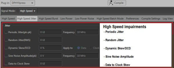
High Speed Jitter - Jitter

High Speed Jitter - De-Emphasis
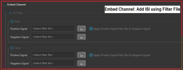
High Speed Jitter - Embed Channel
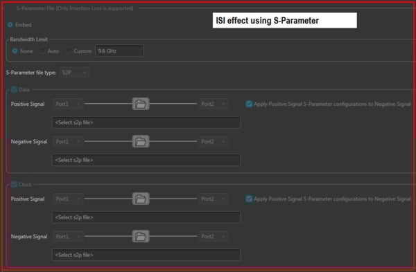
High Speed Jitter - S-Parameter
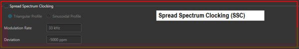
High Speed Jitter - Spread Spectrum Clocking
Low Power mode: The D-PHY v2.0 specification data rate is up to 100 MHz in Low Power mode. The D-PHYXpress application allows you to edit data rate, rise time, pattern type, voltage level, and impairments to emulate the channel effect.
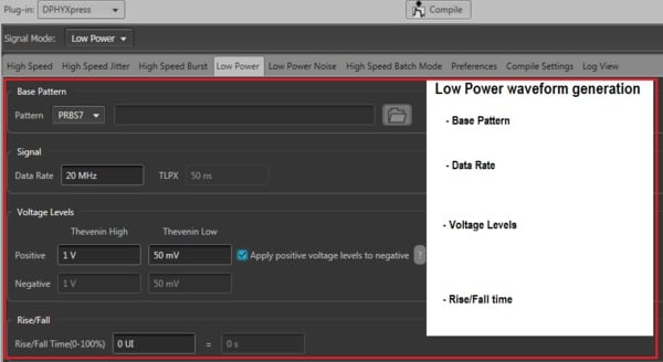
Low Power
The D-PHY v2.0 specification requires Sine/Square noise with eSpike noise.
LP-HS mode: The D-PHYXpress allows you to add Sync Word as per the specification with timing parameters for Data and Clock.
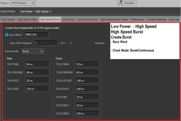
LP-HS mode
Step 2: Calibrate the signal as per CTS requirement
Calibration of signal impairments provides calibration routines that are D-PHY standard specific. The objective of calibration is to compensate the patterns for specific jitter parameters. The typical parameters are Random, Periodic Jitter, and Amplitude. The procedure sequences through all the patterns and each pattern is calibrated independently. These values are used for the Jitter controlled generation of patterns and are injected into the DUT during loopback.
Test coverage
For more details, refer to theReceiver test specificationtable.
Batch mode
Batch mode allows you to create a library of compiled waveforms with incremental Jitter value with a single click.
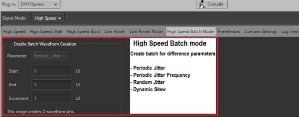
High Speed Batch mode
Scope-based decode for DSI-1 and CSI-2
The SR-DPHY application option enables decoding of DSI-1 and CSI-2 buses. SR-DPHY displays all the decoded components of short packets, long packets, and other communications types such as Bus Turn Around (BTA) and Escape Mode commands. In addition, DCS packets decode the DCS command.
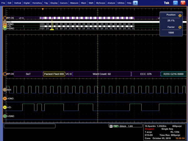
MSO70000C display of decoded digital-channel of a packed pixel stream, 24-bit RGB 8-8-8 format packet
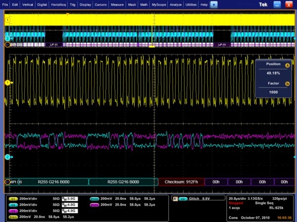
MSO70000C display checksum error of decoded analog-channel of a packed pixel stream
Low-power states: High Speed (LPS HS), Escape (LPS escape), and Bus Turn Around (LPS BTS).
High Speed: Start-of-Transmission (SoT), Short Packets (SP), Long Packets (LgP), and End of Transmission (EoT).
Escape: Escape command (Low-Power data, Ultra-Low Power, Reset trigger, Tearing effect, and Acknowledge) and Low-Power data – will decode as packet data (SP/LgP).
Short packets: Data Type, Virtual Channel, Packet data byte 1, Packet data byte 2, and Error Correcting Code.
Long packets: Data Type, Virtual Channel Word Count, Payload (decoded as pixels or bytes depending upon data type), and Error correcting code.
In addition to decoding DSI-1/CSI-2 acquisitions, SR-DPHY also searches through long acquisitions to find all occurrences of the following packet types:
- Short Packets (specify VC, DT, direction, and packet data values)
- Long Packets (specify VC, DT, direction, WC, and data payload including pixel values)
- Start-of-Transmission (SoT), Stop, End-of-Transmission (EoT), Bus Turn Around (DSI-1 only), Escape mode, ECC warning, ECC error, and Checksum error.
Moving pixel protocol solution
For more information on Moving Pixel solution, refer tohttp://www.movingpixel.com/main.pl?about.html.
Required equipment for D-PHY Transmitter and Receiver testing
For a complete list of required equipment, visithttp://www.tek.com/mipi-0.
Specifications
All specifications apply to all models unless noted otherwise.
Transmitter test specification
- D-PHY base specification
- Revision 1.1 and 1.2
- D-PHY conformance specification
- Revision 1.2
- Measurements
- Both High Speed and Low Power modes, including ULPS and BTA.
- Group 1 tests
- Data lane LP-TX signaling
- 1.1.1
- Data lane LP-TX Thevenin output high level voltage (VOH)
- 1.1.2
- Data lane LP-TX Thevenin output low level voltage (VOL)
- 1.1.3
- Data lane rise time
- 1.1.4
- Data lane fall time
- 1.1.5
- Data lane LP-TX slew rate versus CLOAD (δV/δtSR)
- 1.1.6
- Data lane LP-TX pulse width of exclusive-OR clock (TLP-PULSE-TX)
- 1.1.7
- Data lane LP-TX period of exclusive-OR clock (TLP-PER-TX)
- Group 2 tests
- Clock lane LP-TX signaling
- 1.2.1
- Clock lane LP-TX Thevenin output high level voltage (VOH)
- 1.2.2
- Clock lane LP-TX Thevenin output low level voltage (VOL)
- 1.2.3
- Clock lane rise time
- 1.2.4
- Clock lane fall time
- 1.2.5
- Clock lane LP-TX slew rate vs. CLOAD (δV/δtSR)
- Group 3 tests
- Data lane HS-TX signaling
- 1.3.1
- Data lane HS entry: data lane TLPX value
- 1.3.2
- Data lane HS entry: THS-PREPARE value
- 1.3.3
- Data lane HS entry: THS-PREPARE + THS-ZERO value
- 1.3.4
- Data lane HS-TX differential voltages (VOD(0), VOD(1))
- 1.3.5
- Data lane HS-TX differential voltage mismatch (ΔVOD)
- 1.3.6
- Data lane HS-TX single ended output high voltages (VOHHS(DP),VOHHS(DN))
- 1.3.7
- Data lane HS-TX common-mode voltages (VCMTX(1),VCMTX(0))
- 1.3.8
- Data lane HS-TX common-mode voltage mismatch (ΔVCMTX(1,0))
- 1.3.9
- Data lane HS-TX dynamic common-level variations between 50-450 MHz (ΔVCMTX(LF))
- 1.3.10
- Data lane HS-TX dynamic common-level variations above 450 MHz (ΔVCMTX(HF))
- 1.3.11
- Data lane HS-TX 20%-80% rise time (tR)
- 1.3.12
- Data lane HS-TX 80%-20% fall time (tR)
- 1.3.13
- Data lane HS exit: THS-TRAIL value
- 1.3.14
- Data lane HS exit: 30%-80% Post-EoT rise time (TREOT) value
- 1.3.15
- Data lane HS exit: TEOT value
- 1.3.16
- Data lane HS exit: THS-EXIT value
- Group 4 tests
- Clock lane HS-TX signaling
- 1.4.1
- Clock lane HS entry: TLPX value
- 1.4.2
- Clock lane HS entry: TCLK-PREPARE value
- 1.4.3
- Clock lane HS entry: TCLK-PREPARE + TZERO value
- 1.4.4
- Clock lane HS-TX differential voltages (VOD(0), VOD(1))
- 1.4.5
- Clock lane HS-TX differential voltage mismatch (ΔVOD)
- 1.4.6
- Clock lane HS-TX single ended output high voltages (VOHHS(DP),VOHHS(DN))
- 1.4.7
- Clock lane HS-TX common-mode voltages (VCMTX(1),VCMTX(0))
- 1.4.8
- Clock lane HS-TX common-mode voltage mismatch (ΔVCMTX(1,0))
- 1.4.9
- Clock lane HS-TX dynamic common-level variations between 50-450 MHz (ΔVCMTX(LF))
- 1.4.10
- Clock lane HS-TX dynamic common-level variations above 450 MHz (ΔVCMTX(HF))
- 1.4.11
- Clock lane HS-TX 20%-80% rise time (tR)
- 1.4.12
- Clock lane HS-TX 80%-20% fall time (tR)
- 1.4.13
- Clock lane HS exit: TCLK-TRAIL value
- 1.4.14
- Clock lane HS exit: 30%-80% Post-EoT rise time (TREOT) value
- 1.4.15
- Clock lane HS exit: TEOT value
- 1.4.16
- Clock lane HS exit: THS-EXIT value
- 1.4.17
- Clock lane HS clock instantaneous (UIINST)
- 1.4.18
- Clock Lane HS Clock Delta UI (ΔUI)
- Group 5 tests
- HS-TX Clock-to-Data lane timing
- 1.5.1
- HS entry TCLK-PREValue
- 1.5.2
- HS exit TCLK-POST value
- 1.5.3
- HS clock rising edge alignment to first payload bit
- 1.5.4
- Data-to-Clock skew (TSKEW (TX))
- 1.5.5
- Initial HS Skew Calibration Burst (TSKEWCAL-SYNC, TSKEWCAL)
- 1.5.6
- Periodic HS Skew Calibration Burst (TSKEWCAL-SYNC, TSKEWCAL)
- Group 6 tests
- LP-TX INIT, ULPS and BTA requirements
- 1.6.1
- INIT: LP-TX initialization period (TINIT,MASTER)
- 1.6.2
- ULPS entry: verification of clock lane LP-TX ULPS support
- 1.6.3
- ULPS exit: transmitted TWAKEUP interval
- 1.6.4
- BTA: TX-Side TTA-GO interval value
- 1.6.5
- BTA: RX-Side TTA-SURE interval value
- 1.6.6
- BTA: RX-Side TTA-GET interval value
- Probing configuration
- Single-ended and differential acquisition
- Triggering
- Edge trigger for clock lane tests in clock continuous mode. Choice of width trigger and transition trigger for all other tests and all other modes
- Reports
- Excel xls, HTML, and MHT formats with zoom-in screen shots of the testing regions for each test
Receiver test specification
- D-PHY base specification
- Revision 1.2 and 2.0
- D-PHY conformance specification
- Revision 1.2 and 2.0
- Group 1 tests
- LP-RX voltage and timing requirement
- 2.1.1
- LP-RX Logic 1 Input Voltage (VIH)
- 2.1.2
- LP-RX Logic 0 Input Voltage, Non-ULP State (VIL)
- 2.1.4
- LP-RX Input Hysteresis (VHYST)
- 2.1.5
- LP-RX Minimum Pulse Width Response (TMIN-RX)
- 2.1.6
- LP-RX Input Pulse Rejection (eSPIKE)
- 2.1.7
- LP-RX Interference Tolerance (VINT and fINT)
- Group 2 tests
- LP-RX behavioral requirements
- 2.2.1
- LP-RX Initialization period (TINIT)
- 2.2.2
- ULPS Exit: LP-RX TWAKEUP Timer Value
- 2.2.3
- Clock Lane LP-RX Invalid/Aborted ULPS Entry
- 2.2.4
- Data Lane LP-RX Invalid/Aborted Escape Mode Entry
- 2.2.5
- Data Lane LP-RX Invalid/Aborted Escape Mode Command
- 2.2.7
- Data Lane LP-RX Escape Mode, Ignoring of Post-Trigger-Command Extra Bits
- 2.2.8
- Data Lane LP-RX Escape Mode Unsupported/Unassigned Commands
- Group 3 tests
- HS-RX voltage and set up/hold requirements
- 2.3.1
- HS-RX Common Mode Voltage Tolerance (VCMRX(DC))
- 2.3.2
- HS-RX Differential Input High Threshold (VIDTH)
- 2.3.3
- HS-RX Differential Input Low Threshold (VIDTL)
- 2.3.4
- HS-RX Single-Ended Input High Voltage (VIHHS)
- 2.3.5
- HS-RX Single-Ended Input Low Voltage (VILHS)
- 2.3.6
- HS-RX Common-Mode Interference 50MHz - 450MHz (ΔVCMRX(LF))
- 2.3.7
- HS-RX Common-Mode Interference Beyond 450MHz (ΔVCMRX(HF))
- 2.3.8
- HS-RX Setup/Hold and Jitter Tolerance
- 2.3.9
- HS-RX Setup/Hold and Jitter Tolerance (Spec 2.0, Data rate >=2.5Gbps)
- Group 4 tests
- HS-RX timer requirements
- 2.4.1
- Data Lane HS-RX TD-TERM-EN Value
- 2.4.2
- Data Lane HS-RX THS-PREPARE + THS-ZERO Tolerance
- 2.4.3
- Data Lane HS-RX THS-SETTLE Value
- 2.4.4
- Data Lane HS-RX THS-TRAIL Tolerance
- 2.4.5
- Data Lane HS-RX THS-SKIP Value
- 2.4.6
- Clock Lane HS-RX TCLK-TERM-EN Value
- 2.4.7
- Clock Lane HS-RX TCLK-PREPARE + TCLK-ZERO Tolerance
- 2.4.8
- Clock Lane HS-RX TCLK-SETTLE Value
- 2.4.9
- Clock Lane HS-RX TCLK-TRAIL Tolerance
- 2.4.11
- Clock Lane HS-RX TCLK-PRE and TCLK-POST Tolerance
- Measurements
- Both High Speed and Low Power modes, including ULPS and BTA.
Refer to MOI for detailed procedure.
| Standard | Specs version | Applicable SW options |
|---|---|---|
| D-PHY Transmitter | up to v1.2 | D-PHYTX |
| D-PHY Receiver | up to v2.0 | D-PHYXpress |
Ordering Information
D-PHYTX Automated
| Model | Description |
|---|---|
| DPO7254/C DPO7354/C MSO70000/C DPO70000B/C/DX/SX | DPO (Digital Phosphor Oscilloscope), MSO (Mixed Signal Oscilloscope) Oscilloscopes - 3.5 GHz and above is recommended Where rise time accuracies are not a concern, a 2.5 GHz oscilloscope can also be used. |
| TEKEXP | TekExpress® Automated Compliance Test Software |
| TEKEXP Opt. D-PHYTX | D-PHY Automated Solution for D-PHY Transmitter conformance, characterization, and verification Includes: Latest TekExpress product software DVD kit (P/N 020-2913-xx) and upgrade SW key. Online documentation and printable manual in PDF format are supplied. |
| TEKEXPUP Opt. D-PHYTX | D-PHY Automated Solution for D-PHY Transmitter conformance, characterization, and verification. Order this option if TekExpress (TEKEXP) is already owned. The USB key dongle will be upgraded with Opt. D-PHYTX. Includes: Latest TekExpress product software DVD kit (P/N 020-2913-xx) and upgrade SW key. Online documentation and printable manual in PDF format are supplied. |
D-PHY Essentials
| Model | Description |
|---|---|
| DPO7254/C DPO7354/C MSO70000/C DPO70000B/C/DX/SX | DPO (Digital Phosphor Oscilloscope), MSO (Mixed Signal Oscilloscope) Oscilloscopes - 3.5 GHz and above is recommended. Where rise time accuracies are not a concern, a 2.5 GHz oscilloscope can also be used. |
| DPO7254/C DPO7354/C MSO70000/C DPO70000B/C/DX/SX Opt. D-PHY 1 | D-PHY Essentials for D-PHY Transmitter testing |
| DPO-UP Opt. D-PHY 1 | D-PHY Essentials for D-PHY Transmitter testing upgrade |
| DPOFL-D-PHY1 | D-PHY Essentials for D-PHY Transmitter testing Upgrade (floating license version) |
1Requires DPOJET Jitter and Eye Analysis Tools (Opt. DJA).
| Model | Description |
|---|---|
| Termination board | 1 x TMPC-CTB D-PHY Termination board |
SR-DPHY Decode1
| Model | Description |
|---|---|
| MSO/DPO5000 DPO7000C MSO70000C DPO70000C/D/SX Opt. SR-DPHY | MIPI® D-PHY Serial Analysis DSI-1 and CSI-2 |
| DPO-UP Opt. SR-DPHY | MIPI® D-PHY Serial Analysis DSI-1 and CSI-2 upgrade |
| DPOFL-SR-DPHY | MIPI® D-PHY Serial Analysis DSI-1 and CSI-2 (floating license version) |
1Requires Microsoft Windows 7 OS.
Recommended probes for D-PHY Essentials or D-PHYTX Automated Solution
| Oscilloscope | Probes |
|---|---|
| DPO7000/C | 4x TAP2500/TAP3500/P62451/P6249 1 or 3x TDP3500 (Continuous clock) or 4x TDP3500 (Non-continuous clock) |
| MSO70000/C DPO70000B/C/SX | 4x P7240 or 3x P7330/ P7340A/ P7360A/ P7380A/ P7313 (Continuous clock) or 4x P7330/ P7340A/ P7360A/ P7380A/ P7313 (Non-continuous clock) or 4x P7700 Series (D-PHY Essentials only) |
1Requires TPA-BNC TekProbe2 to TekVPI adapter
D-PHY receiver setup
| Model | Description |
|---|---|
| AWG70002A Options: 01/03/225 Option PRECOMFL-SS01 or PRECOMNL-SS01 on AWG | 10 bit, 2 G Samples record length, 2-channel arbitrary waveform generator |
| AWGSYNC01DPO-UP | Hub for synchronizing multiple AWGs |
| TMPC-MDC4500-4B | MIPI signal conditioning accessory for the AWG 70000 |
| DPO70000C with opt DJA and Probe (For calibration purpose) | 6-8 GHz real-time scope, required for Calibration |
| DPHYNL-SSV1 | D-PHY synthesis software on AWG |
| PSPL 5915 with Opt.100PS | 100 ps Filter (SMA male-to SMA male) |
| 174-6606-00 | SMA cables |
| 174-5771-xx | Phase-matched SMA cable |
Prerequisite host system software requirements for D-PHYTX Automated Solution for D-PHY Transmitter Conformance, Characterization, and Verification
Includes: Latest TekExpress product software DVD kit (P/N 020-2913-xx) and upgrade SW key. Online documentation and printable manual in PDF format are supplied D-PHY Automated Solution for D-PHY Transmitter Conformance, Characterization, and Verification. Order this option if TekExpress (TEKEXP) is already owned. The USB key dongle will be upgraded with Opt. D-PHYTX
Includes: Latest TekExpress product software DVD kit (P/N 020-2913-xx) and upgrade SW key. Online documentation and printable manual in PDF format are D-PHYTX
- Microsoft XP OS with SP2 or later, or Windows 7
- Microsoft Excel 2002 or above
- Microsoft Explorer 6.0 SP1 or later
- Adobe Reader 6.0 or equivalent software for viewing portable document format (PDF) files

Tektronix is registered to ISO 9001 and ISO 14001 by SRI Quality System Registrar. Product(s) complies with IEEE Standard 488.1-1987, RS-232-C, and with Tektronix Standard Codes and Formats. 61W-25621-7


