

Now that you’ve thoroughly tested your first prototype, it’s time to go in for the next revision. In the final part of our 10-part series on power supply design we will walk you through the steps to validate your design.
First, it’s good practice to repeat all the testing steps from parts 1-9, if only as a sanity check. Once everything checks out, you will need to check your design’s reliability.

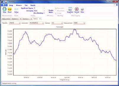
Example of a trend chart for validation testing
Second, test your power supply for all input configurations. This step is crucially important for universal-input power supplies.
Third, sweep the load from no load to full load in order to test your design for all possible operating conditions.
Fourth, run a lifetime test using environmental chambers, which allows you to check the real-life performance of your design.
Remember to use an AC source with universal input ratings. Make sure the AC source is certified for IEC testing. This step will ensure that your product will pass compliance tests.
To make this process a little easier, we suggest using a power analyzer, like the PA1000, on the input and output of the power supply. This step allows you to measure all AC input parameters, such as power factor, crest factor, harmonics, peak current and system efficiency.

Tektronix PA1000 Power Analyzer
The Tektronix PA1000 Power Analyzer comes complete with PWRVIEW software. This package provides custom logging features with user-defined limits, trend, waveforms and harmonic graphing to monitor and automate system testing. To top it off, the complete package also provides power consumption (WHr) testing. Tektronix also recently released a multi-channel power analyzer, the PA3000, for making advanced power consumption and efficiency measurements, and for conformance to various international standards such as Level VI, Energy Star, CEC, IEC62301, and many more. Learn more about the PA3000 here
This completes part 10 of our 10 part blog series on power supply design, walking you through the steps on how to properly select and characterize your components in part one. In part two we discussed prototyping, we then gave your prototype life with some voltage in part three. We showed you how to check the control logic of your design in part four. Next, we moved onto checking the switching characteristics of the power stage in part five. We discussed how to minimize switching and conduction losses in part six. In part seven we helped you through the specification check. Then we moved onto power line compliance testing in part eight. EMI troubleshooting and pre-compliance was covered in part nine and finally design validation and revision in the tenth and final part.
What you do next is up to you. However, a great next step is to learn more about power supplies »
See more in the 10-part series:
Part 1: Component Selection and Characterization for Power Supply Design
Part 2: Low-Voltage DC Circuit Power-On Test
Part 3: High-Voltage AC Circuit Power-On Test
Part 4: Digital and Analog Control Circuit Debug
Part 5: Testing Power Stage Switching Characteristics
Part 6: Switching and Conduction Loss Testing
Part 7: Power Supply Specification Check
Part 8: Power Line Compliance Testing