

You’re designing a new device/component and you just realized that the source measure unit (SMU) instrument that you have been using to perform I-V characterization doesn’t have enough power to test your new device. How are you going to get the job done? You may think you are out of luck if your test requirements exceed the power envelope of your SMU instruments, but it is possible to combine two SMUs in series or parallel to extend their combined DC operating range to meet the needs of your test application.

Combined source measure unit (SMU) DC Voltage Source
Figure 1 shows how two SMUs can be combined in series to achieve double the rated output voltage, and thus double the rated output power, of a single SMU. Both SMUs are configured as voltage sources with their output voltages each set to half of the total desired output voltage. The current limit of the two source measure units should not be set to exactly the same value. The lower of the two current limits will control the current limit of the overall system. The example shown in Figure 1 uses two source measure units to achieve 200V output voltage at 1A for a total 200W of output power.

Figure 1. Series DC voltage source setup
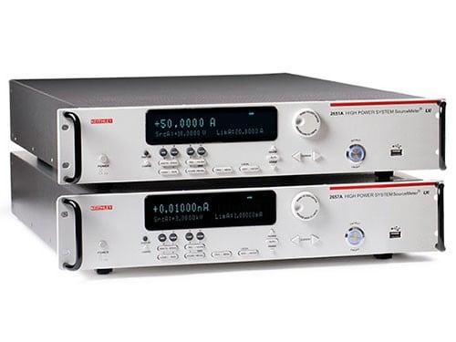
It is important to keep in mind that connecting two voltage sources in series can create hazardous voltage levels that a single source measure unit may not be capable of reaching by itself. This is true if you have two Keithley 2651A High Power SourceMeter® SMU Instruments and combine them together in series. Each one can only output 40V, an intrinsically safe voltage level, but combined in series they can produce 80V which typically requires a safety interlock and other safety features not present on a 40V SMU.
It is also necessary to consider the common mode voltage rating of the SMUs before connecting them in series. The Force LO terminal of a source measure unit can be floated from chassis ground up to specified common mode voltage. If you exceed that common mode voltage by placing two high voltage SMUs in series, you can create a hazardous situation and damage your instruments.
Figure 2 demonstrates a setup that avoids creating unsafe high voltage conditions and common mode voltage problems. By connecting the Force LO terminals of both SMUs to chassis ground, all common mode voltage is removed from the system and the highest voltage, with respect to chassis ground, is only what a single SMU can produce. However, this setup will only work for loads that are isolated from chassis ground because the effective LO terminal of the system is now floating 100V from chassis ground.

Figure 2. Series DC voltage source setup with chassis ground center tap
Combined SMU DC Current Source
Figure 3 shows how two SMUs can be combined in parallel to achieve double the rated output current, and thus double the rated output power, of a single source measure unit. Both SMUs are configured as current sources with their output currents each set to half of the total desired output current. The voltage limit of the two SMUs should not be set to exactly the same value. The lower of the two voltage limits will control the voltage limit of the overall system. The example shown in Figure 3 uses two SMUs to achieve 2A of output current at 100V for a total 200W of output power.

Figure 3. Parallel DC current source setup
Combined SMU Pulsing
It is also possible to combine SMUs together in series or parallel, synchronize their trigger models through TSP-LINK, and create very high voltage or very high current pulses. For example, you can place two Model 2461 Graphical SourceMeter® SMUs in series to achieve pulses up to 200V at 10A or in parallel to achieve 100V pulses at 20A. The same techniques illustrated above are used to create these high power pulses, but there is additional scripting necessary to control the timing of the pulses and ensure tight synchronization.
Figure 4 shows the current and voltage waveforms of a 200V, 10A pulse from two Model 2461s in series. The SMUs were connected together the same way as in the series DC voltage source configuration shown above in Figure 1. The same common voltage issues have to be considered for this setup, but the Keithley 2461 has a maximum common voltage of 250V so this setup did not violate it. Each SMU was configured to source a 100V pulse for a duration of 1ms. The current limit of the first SMU was set at 10A and the second SMU instrument was set to 10.5A. The actual current limit of the system was 10A because the lesser of the two current limits controls the overall system current limit. Figure 5 shows a connection and setup diagram for this example.

Figure 4. A 200V, 10A, 1ms pulse from two Model 2461 SMUs

Figure 5. Series voltage source pulsing setup
Conclusion
You can achieve very high power levels while maintaining the accuracy and precision that SMUs are known for by combining two SMUs in parallel or series. There are a few more complicated ways to combine source measure units in series and parallel to achieve higher power levels, but the basics have been covered above. Combining SMUs can sometimes have dangerous safety implications when high voltages (>40V) are present in the system. Please contact your local Keithley Instruments Field Applications Engineer or the Applications Engineering department at [email protected] or on the Applications support forums at https://forum.tek.com/ before combining SMUs to avoid creating potentially hazardous voltage conditions.
For more information on the products discussed in this blog, click on the following links:
- Keithley 2461 Graphical SourceMeter® Source Measure Unit Instrument
- Keithley 2651A High Power SourceMeter® Source Measure Unit Instrument
To learn more about combining SourceMeter instruments for higher power requirements, download the applications note: Combining Keithley Model 2651A High Power SourceMeter® Instruments for 100A Operation.